EP0765701A1 - Procédé de fabrication des tubes plats pour des échangeurs de chaleur, appareil et tube plat - Google Patents
Procédé de fabrication des tubes plats pour des échangeurs de chaleur, appareil et tube plat Download PDFInfo
- Publication number
- EP0765701A1 EP0765701A1 EP96106244A EP96106244A EP0765701A1 EP 0765701 A1 EP0765701 A1 EP 0765701A1 EP 96106244 A EP96106244 A EP 96106244A EP 96106244 A EP96106244 A EP 96106244A EP 0765701 A1 EP0765701 A1 EP 0765701A1
- Authority
- EP
- European Patent Office
- Prior art keywords
- embossing roller
- embossing
- housing
- cam
- shaft
- Prior art date
- Legal status (The legal status is an assumption and is not a legal conclusion. Google has not performed a legal analysis and makes no representation as to the accuracy of the status listed.)
- Withdrawn
Links
Images

Classifications
-
- F—MECHANICAL ENGINEERING; LIGHTING; HEATING; WEAPONS; BLASTING
- F28—HEAT EXCHANGE IN GENERAL
- F28F—DETAILS OF HEAT-EXCHANGE AND HEAT-TRANSFER APPARATUS, OF GENERAL APPLICATION
- F28F1/00—Tubular elements; Assemblies of tubular elements
- F28F1/02—Tubular elements of cross-section which is non-circular
-
- B—PERFORMING OPERATIONS; TRANSPORTING
- B23—MACHINE TOOLS; METAL-WORKING NOT OTHERWISE PROVIDED FOR
- B23P—METAL-WORKING NOT OTHERWISE PROVIDED FOR; COMBINED OPERATIONS; UNIVERSAL MACHINE TOOLS
- B23P15/00—Making specific metal objects by operations not covered by a single other subclass or a group in this subclass
- B23P15/26—Making specific metal objects by operations not covered by a single other subclass or a group in this subclass heat exchangers or the like
-
- B—PERFORMING OPERATIONS; TRANSPORTING
- B21—MECHANICAL METAL-WORKING WITHOUT ESSENTIALLY REMOVING MATERIAL; PUNCHING METAL
- B21C—MANUFACTURE OF METAL SHEETS, WIRE, RODS, TUBES, PROFILES OR LIKE SEMI-MANUFACTURED PRODUCTS OTHERWISE THAN BY ROLLING; AUXILIARY OPERATIONS USED IN CONNECTION WITH METAL-WORKING WITHOUT ESSENTIALLY REMOVING MATERIAL
- B21C37/00—Manufacture of metal sheets, rods, wire, tubes, profiles or like semi-manufactured products, not otherwise provided for; Manufacture of tubes of special shape
- B21C37/06—Manufacture of metal sheets, rods, wire, tubes, profiles or like semi-manufactured products, not otherwise provided for; Manufacture of tubes of special shape of tubes or metal hoses; Combined procedures for making tubes, e.g. for making multi-wall tubes
- B21C37/08—Making tubes with welded or soldered seams
- B21C37/083—Supply, or operations combined with supply, of strip material
-
- B—PERFORMING OPERATIONS; TRANSPORTING
- B21—MECHANICAL METAL-WORKING WITHOUT ESSENTIALLY REMOVING MATERIAL; PUNCHING METAL
- B21D—WORKING OR PROCESSING OF SHEET METAL OR METAL TUBES, RODS OR PROFILES WITHOUT ESSENTIALLY REMOVING MATERIAL; PUNCHING METAL
- B21D13/00—Corrugating sheet metal, rods or profiles; Bending sheet metal, rods or profiles into wave form
- B21D13/04—Corrugating sheet metal, rods or profiles; Bending sheet metal, rods or profiles into wave form by rolling
-
- B—PERFORMING OPERATIONS; TRANSPORTING
- B21—MECHANICAL METAL-WORKING WITHOUT ESSENTIALLY REMOVING MATERIAL; PUNCHING METAL
- B21D—WORKING OR PROCESSING OF SHEET METAL OR METAL TUBES, RODS OR PROFILES WITHOUT ESSENTIALLY REMOVING MATERIAL; PUNCHING METAL
- B21D53/00—Making other particular articles
- B21D53/02—Making other particular articles heat exchangers or parts thereof, e.g. radiators, condensers fins, headers
- B21D53/04—Making other particular articles heat exchangers or parts thereof, e.g. radiators, condensers fins, headers of sheet metal
-
- F—MECHANICAL ENGINEERING; LIGHTING; HEATING; WEAPONS; BLASTING
- F28—HEAT EXCHANGE IN GENERAL
- F28F—DETAILS OF HEAT-EXCHANGE AND HEAT-TRANSFER APPARATUS, OF GENERAL APPLICATION
- F28F3/00—Plate-like or laminated elements; Assemblies of plate-like or laminated elements
- F28F3/02—Elements or assemblies thereof with means for increasing heat-transfer area, e.g. with fins, with recesses, with corrugations
- F28F3/04—Elements or assemblies thereof with means for increasing heat-transfer area, e.g. with fins, with recesses, with corrugations the means being integral with the element
- F28F3/042—Elements or assemblies thereof with means for increasing heat-transfer area, e.g. with fins, with recesses, with corrugations the means being integral with the element in the form of local deformations of the element
- F28F3/044—Elements or assemblies thereof with means for increasing heat-transfer area, e.g. with fins, with recesses, with corrugations the means being integral with the element in the form of local deformations of the element the deformations being pontual, e.g. dimples
-
- F—MECHANICAL ENGINEERING; LIGHTING; HEATING; WEAPONS; BLASTING
- F28—HEAT EXCHANGE IN GENERAL
- F28F—DETAILS OF HEAT-EXCHANGE AND HEAT-TRANSFER APPARATUS, OF GENERAL APPLICATION
- F28F3/00—Plate-like or laminated elements; Assemblies of plate-like or laminated elements
- F28F3/12—Elements constructed in the shape of a hollow panel, e.g. with channels
Definitions
- the invention relates to a method for producing flat tubes for heat exchangers, a device for producing beaded sheet metal strips for further processing into flat tubes, and a flat tube, the flat tube containing a bead portion on both flat tube sides and a bead-free plug portion on each end.
- Flat tubes for heat exchangers, coolers or the like of the generic type are described, for example, in US Pat. No. 4,470,452. They have a large number of protruding into the interior that are introduced into the flat side walls Bulges, protrusions, beads (English dimples) or the like. on, which should have an obstacle effect on the flow of the fluid in the pipes.
- the flat tubes are made from individual strips of sheet metal by being rolled deformed and laterally crimped, and finally welded or soldered longitudinally at the crimping point.
- the ends of the flat tubes are inserted into slots in heat exchanger manifolds (US Pat. No. 5,052,480, FIG. 4) or water boxes in cooling devices (EP 0 198 581 B1, FIG. 5) and soldered at the contact point. Because of the soldering, the end regions of the flat tubes have no bulges, projections or beads over a certain length (bead-free plug-in sections).
- the object of the invention is to demonstrate a method for producing a flat tube and an associated device, with which flat tubes provided with beads can be produced in a simple and inexpensive manner, in particular flat tubes of different lengths with predetermined but approximately equally long bead-free end regions (plug-in sections) being able to be produced should be.
- the invention opens up the possibility of bulges, beads or the like in a simple and inexpensive manner.
- the cam plate shaft which acts as a breaker in the embossing process in an embossing cycle, enables the continuous sheet metal strip to be processed efficiently.
- the settings of the rotational speeds of one of the embossing rollers and the camshaft disc result in simple, precise handling with respect to the respective embossing runs that can be set in terms of time and length in the same or different ways.
- FIG. 1 shows a section of an endless sheet metal strip 7 produced by the continuous process according to the invention with three bead sections 39 and two complete bead clearances 10.
- a sheet-metal strip delimited in a line-like manner with the flat tube length l contains at the end a bead-free plug-in section 36 with a plug-in section length d.
- the sawing section 37 with the sawing cut width b is taken into account for a setting length a of an embossing run through the device 1 according to the invention.
- the flat tubes with the flat tube length l which is equal to the setting length a minus the saw cut width b, are preferably sawed off equally in a sawing device in the last step of the continuous process.
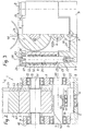
- FIG. 2 shows a device 1 according to the invention for producing a corrugated continuous sheet metal strip 7 for flat heat exchanger tubes of flat tube length l.
- 2 and 3 are to be considered together below, since they represent a front and a side view of the device 1 according to the invention.
- the device 1 essentially contains four cylindrical rollers 2, 3 or shafts 4, 5, which are preferably arranged vertically one above the other.
- the two upper rollers 2, 3 are the counter-embossing roller 2 and the embossing roller 3, of which the one located on the outside is rotatably mounted about a predetermined axis of rotation 6.
- the counter-embossing roller 2 is the roller arranged on the outside on the outside, which is mounted on both sides in the standing housing 9 about the counter-embossing roller axis of rotation 6 and is preferably driven by an external drive.
- the embossing rollers 2, 3 preferably have a much larger diameter than the two shafts 4, 5.
- the embossing roller 3 preferably has equally spaced projections 44 on its circumference, which the beads 18 preferably as groove-shaped, groove-shaped or the like. Generate bulges in the transported continuous sheet metal strip 7 during the embossing pass.
- the projections 44 are formed on the outer surface of the embossing roller 3 essentially in such a way that they have two parallel rows which can produce two parallel rows of beads on the continuous sheet metal strip 7.
- the ball bearing 11, consisting of an inner ring 45, an outer ring 46 and intermediate balls, the inner ring 45 being fixedly connected to the support shaft 5, is provided with two cams 12 and 13, which are ring-like, but with a predetermined, secant-shaped, flat flattening 34 and 35 are formed on the camshaft shaft 4 in connection, wherein the ring-like cam disks 12, 13 are always in contact with the outer ring 46 and roll on the outer ring 46 of the ball bearing 11.
- the two cams 12, 13 are axially adjustable relative to one another on the axis of rotation 40. The adjustment can be done manually.
- the curve of the cam disks 12, 13 represents a flattening 34, 35.
- the curve can also be less convex than the rounding of the disk circumference, but can also be concave.
- the cam shaft 4 is rotatably supported in the sliding housing 8 in the ball bearings 14, 15 and with a preferably provided separate drive (not shown), which is preferably included in the linear lowering / lifting movement of the sliding housing 8 and whose speed of rotation is adjustable.
- a preferably provided separate drive (not shown)
- the sliding housing 8 there are further ball bearings 16, 17, in which the rotary shaft 19 of the embossing roller 3 is mounted.
- the axis of rotation 40 of the camshaft shaft 4 and the axis of rotation 41 of the rotary shaft 19 are mounted at a fixed distance from one another on the sliding housing 8.
- the sliding housing 8 is installed in the standing housing 9 as a spring-loaded part. Between an upper part 26 and a lower part 27 of the standing housing 9 there are preferably four vertically directed columns 28 (each shown in FIG. 3 only one column 28), on which the sliding housing 8 is linearly fastened, by an upper part and a lower part screw connection is slidably supported.
- the sliding housing 8 accordingly has the column-associated, through-going guide openings 29 (only one guide opening 29 is shown in FIG. 3), which surround the columns 28, the respective contact between a continuous guide opening 29 and a column 28 by means of a into the guide opening 29 mounted ball bushing 30 takes place.
- the sliding housing 8 together with the embossing roller 3 and cam disks 12, 13 is linear slidable.
- the comb 24 of the two gears 22, 23 is designed such that it remains when the embossing roller passage 49 is set and when the sliding housing 8 is lowered and the driving counter-embossing roller 2 rotates and drives the embossing roller 3 further via the gears 22, 23 so that the Continuous sheet strip 7 is continuously transported.
- a spring 31 comprising the column 28, in particular a spring ring designed as a rubber ring, which loads the sliding housing 8 around the columns 28 in the direction of the lower parts 27.
- the springs 31 press the sliding housing 8 together with the embossing roller 3 and the cam slide shaft 4 on the ball bearing 11 of the support shaft 5.
- the adjusting screws 48 make contact with the cam disks 12, 13 on the ball bearing 11 of the support shaft 5 such that the elastic rubber rings 31 Press the sliding housing 8 over the cams 12, 13 onto the outer ring of the ball bearing 11 with a spring force that can be varied by the adjusting screw 48.
- a ball bushing 30 which roughly represents a hollow cylinder housing 32, in which there are in a linear manner a large number of balls 33 arranged in series, which touch the column 28 and preferably the linear lifting and lowering of the sliding housing 8 along the four Support or improve columns 28.
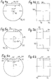
- the cam disks 12, 13 on the cam disk shaft 4 are drawn in uniformly about the axis of rotation 40 and are respectively shown in side and front views.
- the cam disks 12, 13 and the cam disk shaft 4 each essentially represent a round disk with a preferably flat, secant-shaped flattening 34, 35 with a flattening width x in the area shown, the cam disks 12, 13 with the cam disk shaft 4 via the inner ring 45 are firmly connected.
- the cam disk shaft 4 can consist of two essential axle parts (not expressly shown), on each of which one of the cam disks 12 or 13 is located, these axle parts being rotatably mounted with respect to one another and being mutually lockable.
- a cam disk 12 or 13 provided with a secant-shaped flattening 34 or 35, which is connected to a separately arranged, adjustable drive is sufficient, depending on the setting of the rotational speed of the separate drive, to increase or increase the bead clearance 10 with the clearance length c to downsize.
- a second cam disk can be used to reduce the bead clearance 10, by means of the latter Adjustability the free space length c of the bead free space 10 can be varied up to a certain minimum value.
- the setting length a corresponds to a seeping circumferential region pressed against the counter-embossing roller 2 and a lowered, non-beading circumferential area on the embossing roller 3, the length of which is essentially determined both by the set rotational speed of the counter-embossing roller 2 and the set rotational speed of the camshaft shaft 4.
- Approximately half the free space length c corresponds to the plug section length d, with which a soldered flat tube can be inserted into the header tubes of the heat exchanger and then soldered at the contact points.
- FIGS. 6a, 6b An intermediate position to the two FIGS. 4 and 5 with respect to the two axially rotatable cams 12, 13 with the flats 34, 35 can be achieved with their representation in FIGS. 6a, 6b, so that the bead clearance 10 with a clearance length c between the Amounts 0 ⁇ c ⁇ c (max) can be set at constant speed of rotation.
- the clearance length c of the bead free spaces 10 on the continuous sheet metal strip 7 can be adjusted by, in particular, adjusting the cam disks 12, 13 to a reduced, effective curve width x '.
- the rotational speeds of the driving counter-embossing roller 2 and the camshaft shaft 4 can be defined differently by the independence of the two associated drives.
- the speed of rotation can be increased or decreased.
- the adjustment of the adjustment angle 0 ° ⁇ ⁇ (max) 90 ° with respect to the flats 34, 35 of the two cams 12, 13 relative to one another, this is preferably done manually by rotating one of the two cams 12, 13 relative to the adjacent cam 13, 12, the rotary distribution on the side of the sliding housing 8 preferably using a separate rotary knob on an axle part (both not shown) can be done manually, the actuatable rotary knob preferably the camshaft drive opposite.
- the reduced, effective curve width x ' is set by the rotary adjustment.
- an edge elevation 38, 50 of the two cams 12, 13 is achieved on both sides, with which the bead portion 39 can be formed in an almost abrupt manner even in the transition from a bead space 10 to the bead portion 39 with equally deep beads 18 and also in the transition from Bead section 39 in the bead space 10 equal depth beads 18 can be achieved.
- This state can also be achieved with a single cam plate 12 or 13, if instead of two adjusted flattened areas 34, 35 with the reduced curve width x 'a e.g. there is a concave indentation between the edge increases 38.50.
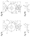
- FIGS. 7a, 8a is a vertically superimposed arrangement of the counter-embossing roller 2, which is mounted at a fixed distance from one another on the one hand, and the support shaft 5 in the standing housing 9 (dotted lines) and from the other at a fixed distance Embossing roller 3, which is mounted relative to one another but vertically displaceable with respect to the standing housing 9, and the camshaft shaft 4 are shown in the displacement housing 8 (dotted lines).
- Laterally at the level of the embossing roller passage 49 is between the counter-embossing roller 2 and the Embossing roll 3 of the unprocessed continuous sheet metal strip 7 can be inserted so that a continuous passage can be ensured.
- embossing roller passage 49 there is a one-sided beading of the continuous sheet metal strip 7 along a predetermined beading section 39 through one of the rotating embossing rollers 2 or 3 provided with pattern-like projections 44.
- the beading is interrupted, preferably at equal intervals, depending on the setting of the rotational speeds of the embossing roller 3 and the camshaft shaft 4 .
- This interruption occurs when a bead clearance 10 following the bead section 39 is provided.
- the spacing of the embossing roller passage 49 is increased by a change in the position of one of the rotating embossing rollers 2 or 3.
- the adjustable, alternating interruption creates an alternating spacing of the embossing roller passage 49, which in each case leads to a bead space 10 between the bead portions 39.
- the rotating embossing roll 2 or 3 is returned to its bead-producing starting position for the bead portion 39 that follows the bead clearance 10.
- the beaded continuous sheet strip 7 leaving the stamping roller passage 49 is then roll-formed into an endless slot-closed flat tube.
- the resulting slit is welded in a connected welding system.
- an approximately central severing of the bead spaces 10 is carried out transversely to the continuous sheet metal strip 7 to produce the flat tubes.
- the intermittent, intermittent enlargement of the embossing roller passage 49 is carried out in particular by lowering the embossing roller 3 by means of a camshaft shaft 4 which has a curve deviating from a circular shape, preferably a flattened portion 34 or 35, the radial lowering / lifting height S / H of which is relative to a support shaft 5 is transferred to the position behavior of the rotating embossing roller 3.
- the radial lowering / lifting height S / H of the embossing roller 3 provided with the beads 18 producing projections 44 is adjusted by curves, in particular mutually adjustable, preferably secant-shaped flats 34, 35 of two cam disks 12, 13 to determine the intermittent enlargement of the embossing roller passage 49.
- the embossing roller 3 is raised in the lifting direction H (marked with an arrow) and the distance to the counter-embossing roller 2 and thus the embossing roller passage 49 is reduced to the original distance.
- the comb 24 remains between the gears 22, 23 of the embossing rollers 2, 3, so that the embossing roller 3 and the counter-embossing roller 2 continue to transport the continuous sheet metal strip 7.
- the camshaft shaft 4 is rotated by its separate drive, the shorter or longer is the time until the bead-free zone 10 ends on the continuous sheet metal strip 7 and the beading is continued.
- the tube roll forming and welding system then the bead clearances 10 in the continuous flat tube are severed transversely in the middle by a downstream sawing device, so that the predetermined flat tubes can subsequently be obtained.
Landscapes
- Engineering & Computer Science (AREA)
- Mechanical Engineering (AREA)
- Physics & Mathematics (AREA)
- Thermal Sciences (AREA)
- General Engineering & Computer Science (AREA)
- Geometry (AREA)
- Shaping Metal By Deep-Drawing, Or The Like (AREA)
- Heat-Exchange Devices With Radiators And Conduit Assemblies (AREA)
Applications Claiming Priority (2)
| Application Number | Priority Date | Filing Date | Title |
|---|---|---|---|
| DE19535834 | 1995-09-26 | ||
| DE19535834A DE19535834A1 (de) | 1995-09-26 | 1995-09-26 | Verfahren zur Herstellung von Flachrohren für Wärmetauscher, Vorrichtung sowie Flachrohr |
Publications (1)
| Publication Number | Publication Date |
|---|---|
| EP0765701A1 true EP0765701A1 (fr) | 1997-04-02 |
Family
ID=7773253
Family Applications (1)
| Application Number | Title | Priority Date | Filing Date |
|---|---|---|---|
| EP96106244A Withdrawn EP0765701A1 (fr) | 1995-09-26 | 1996-04-20 | Procédé de fabrication des tubes plats pour des échangeurs de chaleur, appareil et tube plat |
Country Status (8)
| Country | Link |
|---|---|
| EP (1) | EP0765701A1 (fr) |
| JP (1) | JPH0985334A (fr) |
| KR (1) | KR970016514A (fr) |
| AR (1) | AR001940A1 (fr) |
| AU (1) | AU5610696A (fr) |
| BR (1) | BR9603564A (fr) |
| CA (1) | CA2178513A1 (fr) |
| DE (1) | DE19535834A1 (fr) |
Cited By (13)
| Publication number | Priority date | Publication date | Assignee | Title |
|---|---|---|---|---|
| DE102006033568A1 (de) * | 2006-07-20 | 2008-02-07 | Modine Manufacturing Co., Racine | Herstellungsverfahren für Rohre und Walzenstraße |
| US7921559B2 (en) | 2006-01-19 | 2011-04-12 | Modine Manufacturing Company | Flat tube, flat tube heat exchanger, and method of manufacturing same |
| US8091621B2 (en) | 2006-01-19 | 2012-01-10 | Modine Manufacturing Company | Flat tube, flat tube heat exchanger, and method of manufacturing same |
| US8191258B2 (en) | 2006-01-19 | 2012-06-05 | Modine Manufacturing Company | Flat tube, flat tube heat exchanger, and method of manufacturing same |
| US8281489B2 (en) | 2006-01-19 | 2012-10-09 | Modine Manufacturing Company | Flat tube, flat tube heat exchanger, and method of manufacturing same |
| US8434227B2 (en) | 2006-01-19 | 2013-05-07 | Modine Manufacturing Company | Method of forming heat exchanger tubes |
| US8438728B2 (en) | 2006-01-19 | 2013-05-14 | Modine Manufacturing Company | Flat tube, flat tube heat exchanger, and method of manufacturing same |
| US8561451B2 (en) | 2007-02-01 | 2013-10-22 | Modine Manufacturing Company | Tubes and method and apparatus for producing tubes |
| US8683690B2 (en) | 2006-01-19 | 2014-04-01 | Modine Manufacturing Company | Flat tube, flat tube heat exchanger, and method of manufacturing same |
| US8726508B2 (en) | 2006-01-19 | 2014-05-20 | Modine Manufacturing Company | Flat tube, flat tube heat exchanger, and method of manufacturing same |
| US9038267B2 (en) | 2010-06-10 | 2015-05-26 | Modine Manufacturing Company | Method of separating heat exchanger tubes and an apparatus for same |
| CN112355088A (zh) * | 2020-10-30 | 2021-02-12 | 天津大学 | 一种钢管整体椭圆度加工方法 |
| CN112453198A (zh) * | 2020-10-30 | 2021-03-09 | 天津大学 | 一种钢管整体椭圆度加工装置 |
Families Citing this family (11)
| Publication number | Priority date | Publication date | Assignee | Title |
|---|---|---|---|---|
| KR100364532B1 (ko) * | 1996-12-18 | 2003-03-03 | 엘지전자 주식회사 | 증발기용열교환기 |
| DE29703588U1 (de) * | 1997-02-28 | 1997-11-13 | Schade GmbH & Co. KG, 58840 Plettenberg | Vorrichtung zum Herstellen eines vorzugsweise geschlossenen Hohlprofilabschnittes durch Rollformen |
| DE102004045018B4 (de) * | 2003-09-30 | 2019-08-01 | Mahle International Gmbh | Verfahren zur Herstellung eines flachen Rohres für einen Wärmetauscher eines Kraftfahrzeugs, flaches Rohr, Verfahren zur Herstellung eines Wärmetauschers und Wärmetauscher |
| DE102006018217A1 (de) * | 2006-04-19 | 2007-10-25 | Modine Manufacturing Co., Racine | Wärmetauscher für Kraftfahrzeuge |
| DE102006019823B4 (de) * | 2006-04-28 | 2011-01-27 | Arup Alu-Rohr Und -Profil Gmbh | Verfahren und Vorrichtung zur Herstellung von Rohren |
| JP2008023572A (ja) * | 2006-07-24 | 2008-02-07 | Mori Machinery Corp | 熱交換用チューブの製造ラインにおけるディンプル形成方法と熱交換用チューブの製造ラインに用いるディンプル形成装置 |
| DE102011008118B4 (de) | 2011-01-07 | 2012-10-18 | Arup Alu-Rohr Und Profil Gmbh | Wärmetauscher sowie Mehrkammerflachrohr dafür |
| CN102589337B (zh) * | 2011-01-13 | 2016-02-03 | 摩丁制造公司 | 热交换管及使用该热交换管的方法 |
| CN112570557A (zh) * | 2020-10-29 | 2021-03-30 | 无锡华利达金属制品有限公司 | 一种排气软管伸缩节的冷压机构 |
| CN112264515B (zh) * | 2020-11-05 | 2025-03-18 | 广州鼎航知识产权服务有限公司 | 一种不易变形的扁形铜管及其压制装置 |
| CN120079698B (zh) * | 2025-04-30 | 2025-09-26 | 弗洛德科技(江苏)有限公司 | 一种蒸发器用铝管压扁加工装置 |
Citations (5)
| Publication number | Priority date | Publication date | Assignee | Title |
|---|---|---|---|---|
| US3686917A (en) * | 1971-04-06 | 1972-08-29 | Toyoda Chuo Kenkyusho Kk | Roll forming apparatus |
| US3918626A (en) * | 1971-12-30 | 1975-11-11 | Olin Corp | Method of fabricating patterned tubing from metallic strip |
| JPS61137630A (ja) * | 1984-12-10 | 1986-06-25 | Nippon Steel Metal Prod Co Ltd | ビ−ド成形方法および装置 |
| JPH0428438A (ja) * | 1990-05-21 | 1992-01-31 | Calsonic Corp | 熱交換器用伝熱管の製造方法 |
| WO1995005571A2 (fr) * | 1993-08-04 | 1995-02-23 | Insilco Corporation, Thermal Components Division | Tube de radiateur, procede et dispositif de fabrication |
Family Cites Families (3)
| Publication number | Priority date | Publication date | Assignee | Title |
|---|---|---|---|---|
| DE1527928A1 (de) * | 1966-09-22 | 1970-12-17 | Bliss Co | Maschine zur Formung mindestens einer Laengsrippe im Anfang eines aufgespulten Bandes |
| CA1005365A (en) * | 1973-05-10 | 1977-02-15 | Charles D. Mclain | Patterned tubing and a method of fabricating same from metallic strip |
| DE2452065A1 (de) * | 1973-12-26 | 1975-07-10 | Phelps Dodge Ind Inc | Verfahren und vorrichtung zum herstellen geriffelter rohre |
-
1995
- 1995-09-26 DE DE19535834A patent/DE19535834A1/de not_active Withdrawn
-
1996
- 1996-04-20 EP EP96106244A patent/EP0765701A1/fr not_active Withdrawn
- 1996-05-03 KR KR1019960014373A patent/KR970016514A/ko not_active Withdrawn
- 1996-05-14 AR AR33650996A patent/AR001940A1/es unknown
- 1996-05-15 JP JP8119407A patent/JPH0985334A/ja active Pending
- 1996-06-07 CA CA002178513A patent/CA2178513A1/fr not_active Abandoned
- 1996-06-21 AU AU56106/96A patent/AU5610696A/en not_active Abandoned
- 1996-08-26 BR BR9603564A patent/BR9603564A/pt not_active Application Discontinuation
Patent Citations (5)
| Publication number | Priority date | Publication date | Assignee | Title |
|---|---|---|---|---|
| US3686917A (en) * | 1971-04-06 | 1972-08-29 | Toyoda Chuo Kenkyusho Kk | Roll forming apparatus |
| US3918626A (en) * | 1971-12-30 | 1975-11-11 | Olin Corp | Method of fabricating patterned tubing from metallic strip |
| JPS61137630A (ja) * | 1984-12-10 | 1986-06-25 | Nippon Steel Metal Prod Co Ltd | ビ−ド成形方法および装置 |
| JPH0428438A (ja) * | 1990-05-21 | 1992-01-31 | Calsonic Corp | 熱交換器用伝熱管の製造方法 |
| WO1995005571A2 (fr) * | 1993-08-04 | 1995-02-23 | Insilco Corporation, Thermal Components Division | Tube de radiateur, procede et dispositif de fabrication |
Non-Patent Citations (2)
| Title |
|---|
| PATENT ABSTRACTS OF JAPAN vol. 010, no. 333 (M - 534) 12 November 1986 (1986-11-12) * |
| PATENT ABSTRACTS OF JAPAN vol. 016, no. 195 (M - 1246) 12 May 1992 (1992-05-12) * |
Cited By (14)
| Publication number | Priority date | Publication date | Assignee | Title |
|---|---|---|---|---|
| US8434227B2 (en) | 2006-01-19 | 2013-05-07 | Modine Manufacturing Company | Method of forming heat exchanger tubes |
| US8726508B2 (en) | 2006-01-19 | 2014-05-20 | Modine Manufacturing Company | Flat tube, flat tube heat exchanger, and method of manufacturing same |
| US7921559B2 (en) | 2006-01-19 | 2011-04-12 | Modine Manufacturing Company | Flat tube, flat tube heat exchanger, and method of manufacturing same |
| US8091621B2 (en) | 2006-01-19 | 2012-01-10 | Modine Manufacturing Company | Flat tube, flat tube heat exchanger, and method of manufacturing same |
| US8191258B2 (en) | 2006-01-19 | 2012-06-05 | Modine Manufacturing Company | Flat tube, flat tube heat exchanger, and method of manufacturing same |
| US8281489B2 (en) | 2006-01-19 | 2012-10-09 | Modine Manufacturing Company | Flat tube, flat tube heat exchanger, and method of manufacturing same |
| US8438728B2 (en) | 2006-01-19 | 2013-05-14 | Modine Manufacturing Company | Flat tube, flat tube heat exchanger, and method of manufacturing same |
| US8683690B2 (en) | 2006-01-19 | 2014-04-01 | Modine Manufacturing Company | Flat tube, flat tube heat exchanger, and method of manufacturing same |
| DE102006033568B4 (de) * | 2006-07-20 | 2010-08-05 | Modine Manufacturing Co., Racine | Herstellungsverfahren für Rohre und Walzenstraße zur Durchführung dieses Verfahrens |
| DE102006033568A1 (de) * | 2006-07-20 | 2008-02-07 | Modine Manufacturing Co., Racine | Herstellungsverfahren für Rohre und Walzenstraße |
| US8561451B2 (en) | 2007-02-01 | 2013-10-22 | Modine Manufacturing Company | Tubes and method and apparatus for producing tubes |
| US9038267B2 (en) | 2010-06-10 | 2015-05-26 | Modine Manufacturing Company | Method of separating heat exchanger tubes and an apparatus for same |
| CN112355088A (zh) * | 2020-10-30 | 2021-02-12 | 天津大学 | 一种钢管整体椭圆度加工方法 |
| CN112453198A (zh) * | 2020-10-30 | 2021-03-09 | 天津大学 | 一种钢管整体椭圆度加工装置 |
Also Published As
| Publication number | Publication date |
|---|---|
| AU5610696A (en) | 1997-04-10 |
| JPH0985334A (ja) | 1997-03-31 |
| DE19535834A1 (de) | 1997-04-17 |
| CA2178513A1 (fr) | 1997-03-27 |
| AR001940A1 (es) | 1997-12-10 |
| BR9603564A (pt) | 1998-05-19 |
| KR970016514A (ko) | 1997-04-28 |
Similar Documents
| Publication | Publication Date | Title |
|---|---|---|
| EP0765701A1 (fr) | Procédé de fabrication des tubes plats pour des échangeurs de chaleur, appareil et tube plat | |
| DE69320366T2 (de) | Blattartiges material, verfahren und rollen zur verwendung in diesem verfahren | |
| DE102009024847B4 (de) | Vorrichtung zur Herstellung wendelförmiger Wellrohre | |
| DE2627165A1 (de) | Geriffelter blechstreifen | |
| EP2842653A1 (fr) | Outil et procédé de fabrication de pièces découpées | |
| DE3226221C2 (de) | Vorprodukt-Formwalzensatz zum Krümmen eines ebenen Rohrstreifens | |
| EP3305434B1 (fr) | Cassette conçue pour recevoir un ensemble de rouleaux profilés ou un ensemble de pièces formées par compression destinés à la formation de supports de lamelles ou analogues et outil de formation correspondant | |
| DE112015005188T5 (de) | Druckrollenlagerkäfig und Verfahren zur Herstellung desselben | |
| DE3619648C2 (fr) | ||
| DE102005003558A1 (de) | Rollenwerkzeug zur linienhaften Blechverformung sowie Blechverformungsvorrichtung mit einem derartigen Rollenwerkzeug | |
| DE4335505C1 (de) | Vorrichtung zur Herstellung eines außen verzahnten Getriebeteiles | |
| DE2803365A1 (de) | Verfahren und vorrichtung zur herstellung von mit querrippen versehenen rohren | |
| DE1945346C3 (de) | Zwischenlage für einen Faltenfilter und Gerät zu deren Herstellung | |
| DE3930064C2 (fr) | ||
| DE19818234A1 (de) | Rollprofiliereinrichtung zur Herstellung von Roll- oder Walzprofilelementen | |
| DE8613195U1 (de) | Walzwerk | |
| DE1949394B2 (de) | Metallband für einen gewickelten Bund und Vorrichtung zur Herstellung des Metallbandes | |
| EP0545100B1 (fr) | Dispositif pour cintrer des tôles à ondes trapézoidales | |
| EP3360620A1 (fr) | Procédé et dispositif de fabrication d'un acier d'emballage ondulé pour un emballage structuré | |
| EP1847333A1 (fr) | Méthode de réduction d'épaisseur d'un materiau roulé | |
| DE2232158B2 (de) | Biegerollenlagerung einer formstation zum herstellen von schraubennahtrohren | |
| DE102006025751B4 (de) | Verfahren zur Abdichtung einer Vakuumkammer und Schleuseneinrichtung für eine Vakuumkammer | |
| DE69015779T2 (de) | Einrichtung zum Antreiben eines langgestreckten Körpers in Längsrichtung. | |
| DE102019122958B4 (de) | Lärmreduzierter Zahnriemenantrieb | |
| DE19710060C2 (de) | Vorrichtung zum Richten zylindrischer Werkstücke |
Legal Events
| Date | Code | Title | Description |
|---|---|---|---|
| PUAI | Public reference made under article 153(3) epc to a published international application that has entered the european phase |
Free format text: ORIGINAL CODE: 0009012 |
|
| AK | Designated contracting states |
Kind code of ref document: A1 Designated state(s): AT BE CH DE DK ES FI FR GB GR IE IT LI LU MC NL PT SE |
|
| 17P | Request for examination filed |
Effective date: 19970312 |
|
| RAP1 | Party data changed (applicant data changed or rights of an application transferred) |
Owner name: ARUP ALU-ROHR U. -PROFIL GMBH |
|
| 17Q | First examination report despatched |
Effective date: 19971121 |
|
| STAA | Information on the status of an ep patent application or granted ep patent |
Free format text: STATUS: THE APPLICATION HAS BEEN WITHDRAWN |
|
| 18W | Application withdrawn |
Withdrawal date: 19980227 |