EP0765703B1 - Manchon pour machine a couler sous pression et machine a couler sous pression utilisant ledit manchon - Google Patents
Manchon pour machine a couler sous pression et machine a couler sous pression utilisant ledit manchon Download PDFInfo
- Publication number
- EP0765703B1 EP0765703B1 EP95921161A EP95921161A EP0765703B1 EP 0765703 B1 EP0765703 B1 EP 0765703B1 EP 95921161 A EP95921161 A EP 95921161A EP 95921161 A EP95921161 A EP 95921161A EP 0765703 B1 EP0765703 B1 EP 0765703B1
- Authority
- EP
- European Patent Office
- Prior art keywords
- sleeve
- die
- machine according
- metal material
- casing machine
- Prior art date
- Legal status (The legal status is an assumption and is not a legal conclusion. Google has not performed a legal analysis and makes no representation as to the accuracy of the status listed.)
- Expired - Lifetime
Links
- 238000004512 die casting Methods 0.000 title claims description 45
- XEEYBQQBJWHFJM-UHFFFAOYSA-N Iron Chemical compound [Fe] XEEYBQQBJWHFJM-UHFFFAOYSA-N 0.000 claims description 72
- 239000000956 alloy Substances 0.000 claims description 56
- 229910045601 alloy Inorganic materials 0.000 claims description 55
- 229910000734 martensite Inorganic materials 0.000 claims description 40
- 229910052742 iron Inorganic materials 0.000 claims description 35
- 239000007769 metal material Substances 0.000 claims description 28
- 229910052751 metal Inorganic materials 0.000 claims description 21
- 239000002184 metal Substances 0.000 claims description 21
- 229910001566 austenite Inorganic materials 0.000 claims description 18
- 239000000919 ceramic Substances 0.000 claims description 13
- 238000005299 abrasion Methods 0.000 claims description 12
- 150000004767 nitrides Chemical class 0.000 claims description 11
- 230000007797 corrosion Effects 0.000 claims description 6
- 238000005260 corrosion Methods 0.000 claims description 6
- 229910001141 Ductile iron Inorganic materials 0.000 claims description 4
- 150000001247 metal acetylides Chemical class 0.000 claims 1
- 239000000463 material Substances 0.000 description 24
- 230000000052 comparative effect Effects 0.000 description 16
- OKTJSMMVPCPJKN-UHFFFAOYSA-N Carbon Chemical compound [C] OKTJSMMVPCPJKN-UHFFFAOYSA-N 0.000 description 15
- 238000005266 casting Methods 0.000 description 13
- 239000010439 graphite Substances 0.000 description 11
- 229910002804 graphite Inorganic materials 0.000 description 11
- 238000007711 solidification Methods 0.000 description 11
- 230000008023 solidification Effects 0.000 description 11
- 229910001018 Cast iron Inorganic materials 0.000 description 10
- 230000015572 biosynthetic process Effects 0.000 description 10
- 230000007423 decrease Effects 0.000 description 10
- 238000001816 cooling Methods 0.000 description 9
- 238000009413 insulation Methods 0.000 description 9
- 239000000203 mixture Substances 0.000 description 9
- 230000002093 peripheral effect Effects 0.000 description 8
- 238000010438 heat treatment Methods 0.000 description 7
- 238000010276 construction Methods 0.000 description 6
- 239000013078 crystal Substances 0.000 description 6
- 230000000694 effects Effects 0.000 description 6
- 238000004519 manufacturing process Methods 0.000 description 6
- 239000006104 solid solution Substances 0.000 description 6
- 229910052782 aluminium Inorganic materials 0.000 description 5
- 229910052799 carbon Inorganic materials 0.000 description 5
- 229910010293 ceramic material Inorganic materials 0.000 description 5
- 238000002347 injection Methods 0.000 description 5
- 239000007924 injection Substances 0.000 description 5
- 229910001234 light alloy Inorganic materials 0.000 description 5
- 238000005121 nitriding Methods 0.000 description 5
- 229910000838 Al alloy Inorganic materials 0.000 description 4
- 229910003271 Ni-Fe Inorganic materials 0.000 description 4
- 229910001315 Tool steel Inorganic materials 0.000 description 4
- 238000010586 diagram Methods 0.000 description 4
- 229910000765 intermetallic Inorganic materials 0.000 description 4
- 239000000155 melt Substances 0.000 description 4
- XAGFODPZIPBFFR-UHFFFAOYSA-N aluminium Chemical compound [Al] XAGFODPZIPBFFR-UHFFFAOYSA-N 0.000 description 3
- 238000000034 method Methods 0.000 description 3
- YLQBMQCUIZJEEH-UHFFFAOYSA-N Furan Chemical compound C=1C=COC=1 YLQBMQCUIZJEEH-UHFFFAOYSA-N 0.000 description 2
- 238000005255 carburizing Methods 0.000 description 2
- 230000001419 dependent effect Effects 0.000 description 2
- 230000002708 enhancing effect Effects 0.000 description 2
- 230000004927 fusion Effects 0.000 description 2
- 229910052748 manganese Inorganic materials 0.000 description 2
- 229910052750 molybdenum Inorganic materials 0.000 description 2
- 229910052759 nickel Inorganic materials 0.000 description 2
- 239000010451 perlite Substances 0.000 description 2
- 235000019362 perlite Nutrition 0.000 description 2
- 229910052721 tungsten Inorganic materials 0.000 description 2
- 229910014813 CaC2 Inorganic materials 0.000 description 1
- 229910020101 MgC2 Inorganic materials 0.000 description 1
- 229910001005 Ni3Al Inorganic materials 0.000 description 1
- 229910003217 Ni3Si Inorganic materials 0.000 description 1
- 241000220317 Rosa Species 0.000 description 1
- 229910001035 Soft ferrite Inorganic materials 0.000 description 1
- 229910052804 chromium Inorganic materials 0.000 description 1
- 239000004020 conductor Substances 0.000 description 1
- 238000002425 crystallisation Methods 0.000 description 1
- 230000008025 crystallization Effects 0.000 description 1
- 230000006378 damage Effects 0.000 description 1
- 230000007812 deficiency Effects 0.000 description 1
- 230000002950 deficient Effects 0.000 description 1
- 230000001747 exhibiting effect Effects 0.000 description 1
- 238000010348 incorporation Methods 0.000 description 1
- 230000006698 induction Effects 0.000 description 1
- 230000001939 inductive effect Effects 0.000 description 1
- 239000011159 matrix material Substances 0.000 description 1
- 238000001000 micrograph Methods 0.000 description 1
- 230000004048 modification Effects 0.000 description 1
- 238000012986 modification Methods 0.000 description 1
- 238000001556 precipitation Methods 0.000 description 1
- 238000007528 sand casting Methods 0.000 description 1
- 230000035939 shock Effects 0.000 description 1
- 239000000243 solution Substances 0.000 description 1
- 241000894007 species Species 0.000 description 1
- 238000004381 surface treatment Methods 0.000 description 1
- 230000002459 sustained effect Effects 0.000 description 1
Images



Classifications
-
- B—PERFORMING OPERATIONS; TRANSPORTING
- B22—CASTING; POWDER METALLURGY
- B22D—CASTING OF METALS; CASTING OF OTHER SUBSTANCES BY THE SAME PROCESSES OR DEVICES
- B22D17/00—Pressure die casting or injection die casting, i.e. casting in which the metal is forced into a mould under high pressure
- B22D17/20—Accessories: Details
- B22D17/2015—Means for forcing the molten metal into the die
- B22D17/2023—Nozzles or shot sleeves
-
- C—CHEMISTRY; METALLURGY
- C22—METALLURGY; FERROUS OR NON-FERROUS ALLOYS; TREATMENT OF ALLOYS OR NON-FERROUS METALS
- C22C—ALLOYS
- C22C37/00—Cast-iron alloys
- C22C37/04—Cast-iron alloys containing spheroidal graphite
-
- C—CHEMISTRY; METALLURGY
- C22—METALLURGY; FERROUS OR NON-FERROUS ALLOYS; TREATMENT OF ALLOYS OR NON-FERROUS METALS
- C22C—ALLOYS
- C22C38/00—Ferrous alloys, e.g. steel alloys
- C22C38/02—Ferrous alloys, e.g. steel alloys containing silicon
-
- C—CHEMISTRY; METALLURGY
- C22—METALLURGY; FERROUS OR NON-FERROUS ALLOYS; TREATMENT OF ALLOYS OR NON-FERROUS METALS
- C22C—ALLOYS
- C22C38/00—Ferrous alloys, e.g. steel alloys
- C22C38/08—Ferrous alloys, e.g. steel alloys containing nickel
Definitions
- This invention relates to a sleeve for a die casting machine used for die casting various light alloys represented by aluminum alloy and a die casting machine using the sleeve.
- the die-cast product of a light alloy is manufactured by forcing the melt of the light alloy into a cavity in a pair of dice consisting of a die segment and a stationary die.
- a sleeve is connected through the medium of a bush to the cavity and an injection mouth formed in the sleeve is used for admitting the molten alloy.
- the incoming molten alloy is forced into the cavity with a plunger.
- generally tool steel, SKD61 is used as the material for forming the sleeve.
- An alloy such as disclosed in JP-A-5 302 141 (TOSHIBA) having high thermal insulation and corrosion resistance properties fails in reliability of performance, namely the durability of a sleeve made from this alloy (which contains, by weight, 0.8 to 2.0 % C, 3.0 to 10.0 % Si, 15 to 40 % Ni, 0.03 to 1.0 % of a least one kind selected from Mg and Ca and >0.4 to 10 % Mn, and the balance Fe) is not sufficient.
- the preamble of the independent claims is based on JP-A-5 302 141.
- the feasibility of using a ceramic material of excellent insulation and low thermal expansivity in part of the sleeve is also being studied.
- the ceramic material however, has poor reliability of performance because it is deficient in shock resistance and rigidity. This measure has such problems as inflicting a crack on the interface because of a large difference in thermal expansion coefficient between the ceramic material and the material of the peripheral part. It further has a serious practical problem that the ceramic material is not easily molded in a complicated shape.
- An object of this invention is to provide a sleeve for a die casting machine which offers high thermal insulation, possesses the ability to preclude entry of a solidification phase, and excels in reliability of performance, namely a sleeve for a die-casing machine which acquires enhanced durability.
- Another object of this invention is to provide a sleeve for a die casting machine which allays the difference in thermal expansivity from the peripheral parts and exalts the reliability and durability besides fulfilling the aforementioned conditions, namely a sleeve for a die casting machine which enjoys perfect castability and machinability.
- Still another object of this invention is to provide a die casting machine which, owing to the use of the sleeve of the quality mentioned above, enjoys improved yield and, at the same time, excels in durability and reliability.
- the sleeve for a die casting machine of this invention is set forth and characterised in the main independent claim 1 while the dependent claims 2-14 describe variants.
- the metal material metallographically comprising a martensite phase or a mixed phase of a martensite phase with an austenite phase as a main component and having thermal conductivity of not more than 20 W/mK as described above, the solidification of the molten metal in the sleeve can be curbed and the reliability of the sleeve itself can be exalted.
- the sleeve will neither acquire ample insulation nor permit ample repression of solidification of the molten metal within the sleeve. If the texture of the metal material for the formation of the sleeve does not comprise a mixed phase of a martensite phase with an austenite phase as a main component, the sleeve will not acquire fully satisfactory durability and reliability because the metal material fails to offer ample resistance to abrasion and to galling and preclude deformation by heat fully satisfactorily.
- the mixed phase of a martensite phase with an austenite phase appropriately contains the martensite phase at a proportion of not less than 10% of surface area ratio.
- the sleeve When the sleeve is formed of other material than the metal material such as, for example, a ceramic material, it does not easily acquire perfect reliability.
- the sleeve for a die casting machine according to this invention described above is characterized particularly in that the metal material comprises an iron-based alloy containing at least Ni.
- the Ni-containing iron-based alloy metallographically comprising a martensite phase or a mixed phase of a martensite phase with an austenite phase manifests such hardness as exceeds Hv 300 on the Vickers hardness scale and such low thermal expansivity as is evinced by a thermal expansion coefficient falling in the range of 11 x 10 -6 to 16 x 10 -6 /K besides enjoying low thermal conductivity. Since the resistance to abrasion or to galling can be improved and the decline of clearance due to deformation by heat can be prevented as a result, the sleeve for a die casting machine is enabled to acquire further improvement in durability and reliability.
- the die casting machine of this invention is set forth and characterized in the main independent claim 15 while the dependent claim 16 describe a variant.
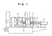
- Fig. 1 is a partially sectioned diagram illustrating the construction of a die casting machine according one embodiment of this invention
- Fig. 2 is a cross section illustrating on a magnified scale the essential part of the die casting machine shown in Fig. 1
- Fig. 3 is a cross section illustrating the construction of a sleeve for a die casting machine according to one embodiment of this invention
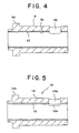
- Fig. 4 is a cross section illustrating a typical modification of the sleeve for a die casting machine shown in Fig. 3
- Fig. 5 is a cross section illustrating the construction of a sleeve for a die casting machine according to another embodiment of this invention
- Fig. 1 is a partially sectioned diagram illustrating the construction of a die casting machine according one embodiment of this invention
- Fig. 2 is a cross section illustrating on a magnified scale the essential part of the die casting machine shown in Fig. 1
- Fig. 3 is a cross section illustrating the construction of a slee
- FIG. 6 is a perspective view illustrating the shape of a product subjected to a die casting test in one embodiment of this invention
- Fig. 7 is a photomicrograph illustrating on a magnified scale the metallographical texture of a sleeve for a die casting machine manufactured in Example 1 of this invention
- Fig. 8 is a photomicrograph illustrating on a magnified scale the metallographical texture of a sleeve for a die casting machine manufactured in Comparative Example 2
- Fig. 9 is a photo-micrograph illustrating on a magnified scale the metallographical texture of a sleeve for a die casting machine manufactured in Example 4 of this invention.
- Fig. 1 is a diagram illustrating the construction of a die-casing machine according to one embodiment of this invention.
- Fig. 2 is a diagram illustrating as magnified the essential part thereof.
- 1 represents a pair of die consisting of a movable die 2 and a stationary die 3.
- the pair of die 1 defines a cavity 4.
- a bush 5 is so disposed as to be connected to the cavity 4.
- To the bush 5 is also connected a sleeve 6.
- the sleeve 6 is supported by a platen 7.
- the sleeve 6 assumes a cylindrical shape as illustrated in Fig. 3.
- the sleeve 6 is provided one terminal side thereof with a molten metal inlet 6a and on the other terminal side thereof with a flange 6b.
- the molten metal is poured in through the molten metal inlet 6a provided in the sleeve 6.
- a plunger tip 8 is movably disposed.
- a plunger rod 10 which is driven by a drive mechanism such as, for example, a hydraulic cylinder 9.
- the molten metal poured in through the molten. metal inlet 6a is forced into the cavity 4 by the plunger tip 8 when the hydraulic cylinder 9 is actuated.
- the movable die 2 is adapted to be moved by a die moving mechanism such as, for example, a hydraulic cylinder 11.
- a die moving mechanism such as, for example, a hydraulic cylinder 11.
- the sleeve 6 is formed of a metal material which metallographically comprises a martensite phase or a mixed phase of a martensite phase with an austenite phase as a main component and has thermal conductivity of not more than 20 W/mK.
- the thermal conductivity of the metal material of which the sleeve 6 is formed exceeds 20 W/mK, the metal material will not acquire ample insulation and will not amply prevent the molten metal in the sleeve 6 from being solidified.
- the thermal conductivity of the metal material is not more than 18 W/mK, preferably not more than 16 W/mK.
- the metal material of which the sleeve 6 is formed does not metallographically comprise a martensite phase or a mixed phase of a martensite phase with an austenite phase as a main component, it will be unable to impart ample durability and reliability to the sleeve because it will not offer ample resistance to abrasion or galling or allow ample preclusion of deformation of the sleeve by heat.
- the metal material Generally in the die casting of an aluminum-based alloy, since the working temperature of the sleeve 6 is in the approximate range of 373 to 673K, the metal material appropriately satisfies the thermal conductivity mentioned above in this temperature range.
- an iron-based alloy having a high Ni content may be cited.
- Ni forms a solid solution with Fe in a wide range of ratio of combination up to about 76 wt% Ni-Fe.
- the intermediate range in the approximate range of 20 to 40 wt% Ni
- the area of low thermal conductivity exists. It is an austenite phase that forms the main phase of the iron-based alloy having a Ni content in the approximate range of 20 to 40 wt% mentioned above.
- the low thermal conductivity can be obtained because the regularity of crystal is lowered and the motion of electrons and phonons which govern the conduction of heat in metal is decelerated in accordance as the composition deviates from the pure Fe having high regularity of crystal structure or from the 76 wt% Ni-Fe forming an intermetallic compound FeNi 3 .
- the Ni-containing iron-based alloy which is formed solely of an austenite phase has low rigidity and imparts no sufficient durability to the sleeve 6.
- the thermal conductivity of this alloy begins to rise when the Ni content thereof is in the neighborhood of below 20% by weight.
- the Ni-containing iron-based alloy When the Ni-containing iron-based alloy is caused to form in the metallographic texture thereof not less than 10% by surface area ratio of a martensite phase, it acquires an increase in rigidity and represses a rise of thermal conduction even when the Ni content is below 19% by weight and consequently fulfills thermal conductivity of not more than 20 W/mK. Further, the Ni-containing iron-based alloy which has formed a martensite phase therein can fulfill the requirement for low thermal expansivity.
- the hardness of the Ni-containing iron-based alloy having not less than 10% by surface area ratio of a martensite phase is not less than Hv 300 on the Vickers hardness scale, for example.
- the thermal expansion coefficient of this alloy is specifically in the approximate range of 11 to 16 x 10 -6 /K in the temperature range of from room temperature to 573K in which the sleeve 6 is heated. Since the peripheral parts of the sleeve such as, for example, the bush 5, platen 7, and plunger tip 8 are generally made of ductile cast iron, for example, the peripheral parts of the sleeve and the sleeve 6 are allowed to have substantially equal thermal expansion coefficients. As a result, the thermal deformation of the sleeve 6 and the peripheral parts thereof is repressed. The decline of the clearance attendant on the thermal deformation and the galling consequently induced, therefore, can be prevented.
- the resistance of the sleeve 6 to abrasion and galling can be improved and, at the same time, the decline of the clearance attendant on thermal deformation can be prevented by using the Ni-containing iron-based alloy which has a metallographic texture producing a martensite phase therein as described above.
- the sleeve 6 which is formed of the Ni-containing iron-based alloy which has a metallographic texture producing a martensite phase therein therefore, amply represses solidification of the molten metal and, at the same time, acquires outstanding durability and reliability.
- the metallographic texture of the Ni-containing iron-based alloy as the material for the formation of the sleeve 6 a texture formed mainly of a mixed phase of a martensite phase with an austenite phase and a texture formed mainly of a martensite phase may be cited.
- the mixed phase of a martensite phase with an austenite phase may have a texture such that the martensite phase may be dispersed in the austenite phase as the main phase.
- the surface area ratio of the martensite phase nevertheless is appropriately equal to or greater than that of the austenite phase.
- the mixed phase has a martensite phase as a main phase thereof (not less than 60% by surface area ratio, for example).
- the Ni-containing iron-based alloy is allowed to have a metallographic texture which is formed substantially solely of a martensite phase, the metallographic texture appropriately has a residual austenite phase for the sake of improving toughness and service life before fatigue and, at the same time, acquiring perfect workability.
- the metallographic texture of the Ni-containing iron-based alloy is varied by the Ni content, the Si content which will be specifically described herein below, the cooling speed after the casting or heat treatment, etc.
- the Ni content in the Ni-containing iron-based alloy is set in the range of 7 to 19% by weight for the purpose of ensuring the production of the martensite phase as described above and consequently fulfilling the requirements for low thermal conductivity and low thermal expansivity. If the Ni content in the iron-based alloy mentioned above is less than 7% by weight, the amount of Ni in the solid solution thereof with iron will decrease, the thermal conductivity will increase, the texture will give rise to a soft ferrite phase or perlite phase, and the durability will decline.
- the Ni content exceeds 19% by weight, the amount of the martensite phase to be produced will decrease and the thermal conductivity and the thermal expansion coefficient will both increase.
- the Ni content is set in the range of 10 to 15% by weight because the alloy having this Ni content acquires low thermal conductivity.
- Ni-containing iron-based alloy described above is enabled to have the thermal conductivity thereof further lowered by incorporating therein a solid solution alloy element having a large difference in atomic radius from iron.
- a solid solution alloy element having a large difference in atomic radius from iron.
- Si, Al, Ti, etc. may be cited. Since Al forms an intermetallic compound with Ni (Ni 3 Al) and Ti forms a carbide, these elements have the possibility of rather increasing the thermal conductivity. Since these elements are allowed to be incorporated in extremely small amounts, their effects are meager. Al, in an approximate amount of not more than 0.5% by weight, manifests an effect in lowering the thermal conductivity.
- Si avoids forming an intermetallic compound and can be incorporated in an approximate amount of up to 8% by weight in the Ni-Fe alloy and consequently serves as an effective element for lowering the thermal conductivity.
- a 7 to 19 wt% Ni-Fe alloy is caused to add 7% by weight of Si, the addition results in forming an intermetallic compound Ni 3 Si.
- the amount of Si so incorporated is up to about 8% by weight, the thermal conductivity can be lowered owing to the contribution of a solid solution to be formed consequently.
- the effect of the addition of Si in lowering the thermal conductivity becomes conspicuous when the amount of Si increases to the proximity of 3% by weight.
- the Si content in the Ni-containing iron-based alloy is in the range of 3 to 8% by weight.
- the rate at which the sleeve 6 formed of the Ni-containing iron-based alloy is to be cooled after the casting or the heat treatment is properly not more than 10 K/min.
- the Ni content and the Si content conform with the standards specified above, an excess of the cooling speed after the casting or the heat treatment over 10 K/min is liable to increase the amount of the austenite phase, lower the hardness, and raise the thermal expansion coefficient.
- the sleeve properly has a wall thickness of not less than 10 mm.
- the Ni-containing iron-based alloy destined to serve as the material for forming the sleeve 6 is used as cast iron by further incorporating therein 0.6 to 2.0% by weight of C, 0.03 to 0.1% by weight of at least one element selected from between Mg and Ca, and not more than 1.0% by weight of Mn.
- the alloy by adding C and inducing precipitation of graphite crystals in the metallographic texture thereof, is enabled to acquire the same castability and machinability as are common to ordinary cast iron. If the C content is less than 0.6% by weight, the crystallization of graphite will not occur. If it exceeds 2.0% by weight, coarse graphite will arise and the strength will decline.
- the effectiveness of carbon in a solid solution in lowering the thermal conductivity grows in accordance as the amount of carbon increases. It is further appropriate to set the total carbon content in a low range of from 0.6 to 1.0% by weight. When the machinability constitutes an important consideration, it is proper to set the C content in the range of from 1.5 to 2.0% by weight.
- Graphite itself is a good conductor of heat.
- the graphite flakes continue into one another and, therefore, have good possibility of impairing low thermal conductivity.
- the graphite is appropriately spheroidized by addition to the alloy of at least one element selected from between Mg and Ca in an amount in the range of 0.03 to 0.1% by weight.
- the graphite in the graphitized texture has only a sparing effect on thermal conductivity because the graphite spheres independently exist in the matrix of iron. If the content of Mg or Ca is less than 0.03% by weight, the carbon will not be amply spheroidized. Conversely, if the content of Mg or Ca exceeds 1.0% by weight, the excess will go to form a carbide (such as, for example, MgC 2 or CaC 2 ) and entrain an increase in thermal conductivity.
- a carbide such as, for example, MgC 2 or CaC 2
- Mn is a basic component of cast iron and functions as a deoxidizer and a component for enhancing corrosion resistance. If the content of Mn exceeds 1.0% by weight, the excess gives rise to a carbide ⁇ (Fe, Mn) 3 C, for example ⁇ and raises thermal conductivity. It is, therefore, proper to set the upper limit of the Mn content at 1.0% by weight.
- the Ni-containing iron-based alloy mentioned above specifically the Ni-containing spheroidal graphite cast iron
- a surface-treated layer of high hardness such as, for example, a ceramic layer 13 on the inner wall surface 6c of the sleeve 6 as illustrated in Fig. 4.
- the surface-treating method for the formation of the ceramic layer 13 the treatment of nitriding, treatment of boriding, treatment of carburizing, etc. may be cited.
- the use of the surface-treating method permits production of a ceramic layer 13 of high hardness having a nitride, a boride, or carbide as a main component.
- the ceramic layer 13 of high hardness imparts improved abrasion resistance to the sleeve 6.
- the galling and the abrasion between the inner wall surface 6c of the sleeve 6 and the plunger tip 8 is prevented more effectively.
- the nitride, boride, or carbide which exists as the ceramic layer 13 can bring about an effect of enhancing the resistance to corrosion caused as by the molten aluminum.
- the Ni-containing iron-based alloy preparatorily to the formation of the ceramic layer 13 as described above, it is appropriate for the Ni-containing iron-based alloy to have incorporated therein such elements as Cr, W, and Mo which readily form a nitride, a boride, or a carbide.
- the preparatory incorporation of these elements enables the ceramic layer 13 to be formed in a large thickness.
- the surface treatment such as the treatment of nitriding, treatment of boriding, treatment of carburizing, etc. enables the nitride, boride, carbide, etc. to be formed to a greater depth. If the carbide is formed in other part than the surface part, it will raise the thermal conductivity. It is proper, therefore, to minimize the amounts of such element as Cr, W, Mo, etc. to be added, specifically to amounts of not more than 2% by weight, for example.
- Fig. 5 is cross section illustrating the construction of a sleeve for a die casting machine according to another embodiment of this invention.
- 14 represents a sleeve of low thermal conductivity which is formed of the same metal material of low thermal conductivity as is described in the preceding embodiment, i.e. an Ni-containing iron-based alloy possessing a metallographic texture which has produced a martensite phase, for example.
- the sleeve 14 of low thermal conductivity is provided with a molten metal inlet 14a. Inside this sleeve 14 of low thermal conductivity, a cylinder 15 provided similarly with a molten metal inlet 15a is inserted.
- the cylinder 15 is formed of an abrasion-resistant alloy or a corrosion-resistant alloy different in species from the metal material of which the sleeve 14 of low thermal conductivity.
- the sleeve 14 of low thermal conductivity and the cylinder 15 jointly form a double-wall sleeve 16.
- the Ni-containing iron-based alloy mentioned above (and the Ni-containing spheroidal graphite cast iron as well) has a thermal expansion coefficient closely approximating to that of tool steel.
- the cylinder 15 formed of an abrasion-resistant alloy or a corrosion-resistant alloy, specifically tool steel is used as inserted in the sleeve 14 of low thermal conductivity, therefore, it cannot induce thermal deformation while in service.
- the double-wall sleeve 16 relies on the sleeve 14 of low thermal conductivity on the periphery to fulfill the role of insulation and the cylinder 15 inserted therein to discharge the role of abrasion with the plunger tip 8. It is, therefore, permits further enhancement of durability.
- Varying casting materials of compositions shown in Table 1 were each melted in a high-frequency induction electric oven of 100 kg and cast by the use of a FURAN sand casting die to produce a sleeve of a structure shown in Fig. 3.
- the sleeve of Example 1 had a cast wall thickness of 20 mm and the sleeve of Example 2 a cast wall thickness of 6 mm.
- the cooling speed (to 423K) of the sleeve of Example 1 after the casting was 0.1 K/sec and the cooling speed (to 423K) of the sleeve of Example 2 after the casting was 1.0 K/sec.
- Table 1 additionally show the properties of the casting materials mentioned above.
- sleeves of the same shape as in the working examples mentioned above were manufactured by using tool steel, SKD61, as a conventional material (hardened material) (Comparative Example 1) and a casting material of a composition shown in Table 1 having a small Ni content (Comparative Example 2).
- the sleeves of Comparative Example 1 and Comparative Example 2 both had a wall thickness of 15 mm.
- the cooling speed (to 423K) of these sleeves after the casting was 0.3 K/sec.
- sleeves of the same shape as in the working examples mentioned above were manufactured by using austenite grade casting material of the compositions shown in Table 1.
- the sleeves of Referential Examples 1 and 2 both had a wall thickness of 20 mm.
- the cooling speed (to 423K) of the sleeves of Referential Examples 1 and 2 after the casting was 0.3 K/sec.
- Table 1 additionally shows the compositions and properties of Comparative Examples 1 and 2 and Referential Examples 1 and 2.
- a test piece was cut from the sleeve (cast product) of Example 1 and this test piece was observed under a microscope (200 magnifications) to determine the metallographic texture thereof.
- a photomicrograph of the metallographic texture is shown in Fig. 7. It is clearly noted from Fig. 7 that the metallographic texture produced spheroidal graphite crystals therein and possessed about 90% by surface area ratio of a martensite phase.
- the sleeve (cast product) of Example 2 was similarly observed under a microscope (200 magnifications) to determine the metallographic texture.
- the metallographic texture was found to have produced spheroidal graphite crystals therein and formed about 20% by surface area ratio of a martensite phase.
- the sleeve (cast product) of Comparative Example 2 was similarly observed under a microscope (200 magnifications) to determine the metallographic texture.
- the metallographic texture is found to have formed about 30% by surface area ratio of a martensite phase and the balance of a perlite phase. The reason for this texture is that the Ni content of the sleeve had an unduly low Ni content.
- a photomicrograph (200 magnifications) of the metallographic texture of the sleeve (cast product) of Referential Example 1 is shown in Fig. 8. It is clearly noted from Fig. 8 that the sleeve of Referential Example 1 produced spheroidal graphite crystals and formed nearly 100% of an austenite phase, with no sign of production of a martensite phase.
- the surface area ratio of the martensite phase in the sleeve of Referential Example 2 was about 5%.
- the sleeves of Examples 1 and 2, Comparative Examples 1 and 2, and Referential Examples 1 and 2 mentioned above were each set in place in a 250-ton die casting machine illustrated in Fig. 1 and die-cast experimentally under the conditions shown in Table 2.
- the die casting produces annular products, 150 mm in outside diameter D, 10 mm in cross-sectional size w, and 10 mm in thickness t, as shown in Fig. 6.
- the annular products of this construction because of a large ratio of surface area to volume, incur a sharp decline of the temperature of molten metal and pose the occurrence of furrows on the product surface as a serious problem.
- the sleeves were rated for resistance to galling based on the degree of occurrence of streaks on the inner wall of sleeve. The ratings of the sleeves for resistance to galling were on a par with those of the conventional nitrided hardened material, SKD61.
- the sleeves of Example 1 and Example 2 incurred the occurrence of furrows on the product surface to a lesser extent and afforded the products with a highly satisfactory yield even in the area of low injection speed at which the gas would be enfolded and the die corroded only sparingly. It is further noted that the sleeves had no problem of entailing deformation or decline of clearance due to thermal expansion and excelled in resistance to galling because the thermal expansion coefficients thereof were on a par with that of the material, SKD61, for the platen and the plunger and further because they had high degrees of hardness.
- Sleeves of the same shape as those of Example 1 were manufactured by using cast iron materials whose compositions, cooling speeds, surface area ratios of martensite phase, and various properties were shown in Table 4. These sleeves were each tested for performance and durability with a die casting machine under the same conditions as those of Example 1. The yields of products and the degrees of resistance to galling obtained at an injection speed of 1.2 m/s are shown additionally in Table 4.
- Fig. 9 shows a photomicrograph (200 magnifications) of the metallographic texture of the sleeve of Example 4.
- a sleeve was manufactured with cast iron of low thermal conductivity having the same composition as that of Example 1 and machined to prescribed dimensions. Then, a nitride layer was formed as the ceramic layer 13 by performing an ion nitriding treatment on the inner wall surface 6a of the sleeve 6 as shown in Fig. 4. This nitride layer served to improve the resistance to loss by fusion because it formed a nitride not easily wetted by molten Al. The nitride layer possessed hardness of Hv 1000 to 1200 and a depth of 5 to 10 ⁇ m.
- the maximum number of shots obtained by the sleeve prior to the formation of the nitride layer without impairing the service life thereof was 5,000 to 10,000 on account of the loss by fusion into the molten aluminum and the wear by friction with the plunger.
- the formation of the nitride layer on the inner wall surface 6a of the sleeve 6 in the present example improved the maximum number of shots about three to four times to 20,000 to 40,000.
- Sleeves were manufactured with cast iron materials of low thermal conductivity having the same compositions as those of Examples 2 to 7 and machined to prescribed dimensions. Then, the inner wall surfaces of the sleeves manufactured with the same materials as those of Example 2 and Example 4 were subjected to a boriding treatment and the inner wall surfaces of the sleeves manufactured with the same materials as those of Example 2 and Example 4 were subjected to a nitriding treatment, severally to form a ceramic layer. In the sleeves of Examples 9 to 14, the formation of the ceramic layer improved the number of shots to about three to four times that prior to the formation of the ceramic layer.
- a double-wall sleeve 16 was manufactured by inserting a cylinder 15 formed of SKD61 in a sleeve 14 of cast iron of low thermal conductivity having the same composition as that of Example 1 as illustrated in Fig. 5.
- the double-wall sleeve 16 of this example was so constructed that the sleeve 11 of cast iron of low thermal conductivity on the peripheral part played the role of insulation and the cylinder 15 of SKD61 inserted inside the sleeve 11 discharged the roll of withstanding the friction with the plunger.
- the cylinder 15 of SKD61 had undergone a nitriding hardening treatment.
- the sleeve 11 of cast iron of low thermal conductivity did not induce thermal deformation while in service because the thermal expansion coefficient thereof was substantially equal to that of the cylinder 15 of SKD61.
- the double-wall sleeve 16 of this example enjoyed a service life of 20,000 to 30,000 shots. Naturally, the improvement in insulation prevented the die-cast products from forming furrows on the surface. As a result, the overall yield of the die-cast products obtained herein was about 1.5 times that of the die-case products of the conventional sleeves.
- a sleeve of the same shape as that of Example 2 was manufactured by using Sialon exhibiting the properties shown in Table 5. This sleeve was set in place in the same die casting machine as that of Example 2 and then tested for service life, with the temperature of the melt of ADC12 poured into the sleeve varied in the range of 943 to 973K. The results are shown in Table 6.
- the sleeve for a die casting machine according to this invention is formed of a metal material possessing low thermal conductivity and, at the same time, excelling in reliability, it can prevent the temperature of the molten metal introduced therein from being lowered, improve the quality of a die-cast product, and exalt the reliability of the sleeve. Then, the die casting machine according to this invention affords die-cast products with high yield and, at the same time, improves the durability and the reliability of the machine proper notably because it uses the sleeve of the quality mentioned above.
- the sleeve for a die casting machine and the die casting machine according to this invention are useful for the manufacture of die-cast products of various light alloys represented by aluminum alloy.
Landscapes
- Chemical & Material Sciences (AREA)
- Engineering & Computer Science (AREA)
- Mechanical Engineering (AREA)
- Materials Engineering (AREA)
- Metallurgy (AREA)
- Organic Chemistry (AREA)
- Molds, Cores, And Manufacturing Methods Thereof (AREA)
- Injection Moulding Of Plastics Or The Like (AREA)
- Moulds For Moulding Plastics Or The Like (AREA)
Claims (16)
- Manchon (6) pour une machine à couler sous pression, adapté pour servir simultanément de récepteur de métal fondu et de compresseur dans ladite machine à couler sous pression et réalisé dans un matériau métallique ayant une conductivité thermique inférieure à 20 W/mk, caractérisé en ce que ledit matériau métallique comprend de façon métallographique une phase martensitique ou une phase mixte composée d'une phase martensitique associée à une phase austénitique.
- Manchon (6) pour une machine à couler sous pression selon la revendication 1, dans lequel ledit matériau métallique comprend un alliage à base de fer contenant au moins du Ni.
- Manchon (6) pour une machine à couler sous pression selon la revendication 1, dans lequel ladite phase mixte n'a pas moins de 10% par rapport d'aire de surface d'une phase martensitique.
- Manchon (6) pour une machine à couler sous pression selon la revendication 2, dans lequel ledit alliage à base de fer contient de 7 à 19% en poids de Ni.
- Manchon (6) pour une machine à couler sous pression selon la revendication 4, dans lequel ledit alliage à base de fer contient en outre de 3 à 8% en poids de Si.
- Manchon (6) pour une machine à couler sous pression selon la revendication 5, dans lequel ledit alliage à base de fer contient en outre de 0,3 à 2% en poids de C, de 0,03 à 0,1% en poids d'au moins un élément sélectionné entre Mg et Ca, et pas plus de 1,0% en poids de Mn.
- Manchon (6) pour une machine à couler sous pression selon la revendication 6, dans lequel ledit alliage à base de fer est de la fonte à graphite sphéroïdal.
- Manchon (6) pour une machine à couler sous pression selon la revendication 1, dans lequel ledit matériau métallique a une dureté de pas moins de Hv 300 sur l'échelle de dureté de Vickers.
- Manchon (6) pour une machine à couler sous pression selon la revendication 8, dans lequel ledit matériau métallique a un coefficient de dilatation thermique de 11 x 10-6 à 16 x 10-6/K dans une plage de températures allant de la température ambiante à 573 K.
- Manchon (6) pour une machine à couler sous pression selon la revendication 1, dans lequel ledit matériau métallique a une conductivité thermique inférieure à 18 W/mK.
- Manchon (6) pour une machine à couler sous pression selon la revendication 2, dans lequel ledit manchon est prévu au moins dans une partie de sa surface de paroi intérieure avec une couche très dure ayant subi un traitement de surface.
- Manchon (6) pour une machine à couler sous pression selon la revendication 11, dans lequel ladite couche ayant subi un traitement de surface est une couche de céramique.
- Manchon (6) pour une machine à couler sous pression selon la revendication 12, dans lequel ladite couche de céramique contient au moins un élément sélectionné dans le groupe composé des borures, nitrures et carbures en tant que composant principal de celle-ci.
- Manchon (6) pour une machine à couler sous pression selon la revendication 2, dans lequel ledit manchon contient un cylindre réalisé dans un alliage résistant à la corrosion ou un alliage résistant à l'abrasion d'un genre différent dudit matériau métallique.
- Machine à couler sous pression, comprenant :caractérisée en ce que ledit manchon (6) est réalisé dans un matériau métallique comprenant en outre de façon métallographique une phase martensitique ou une phase mixte composée d'une phase martensitique associée à une phase austénitique.une paire de matrices (1) composée d'une matrice fixe (3) et d'une matrice mobile (2).un palier (5) disposé dans ladite matrice fixe (3),un manchon (6) connecté audit palier (5), adapté pour servir simultanément de récepteur de métal fondu et de compresseur, et réalisé dans un matériau métallique ayant une conductivité thermique inférieure à 20 W/mK,un piston (8) pour amener le métal fondu introduit dans ledit manchon (6) à être poussé dans ladite paire de matrices (1), etun mécanisme d'entraínement (9) pour ledit piston (8),
- Machine à couler sous pression selon la revendication 15, dans laquelle ledit matériau métallique dans lequel est réalisé ledit manchon comprend un alliage à base de fer contenant au moins du Ni.
Applications Claiming Priority (4)
| Application Number | Priority Date | Filing Date | Title |
|---|---|---|---|
| JP13210394 | 1994-06-14 | ||
| JP13210394 | 1994-06-14 | ||
| JP132103/94 | 1994-06-14 | ||
| PCT/JP1995/001177 WO1995034394A1 (fr) | 1994-06-14 | 1995-06-13 | Manchon pour machine a couler sous pression et machine a couler sous pression utilisant ledit manchon |
Publications (3)
| Publication Number | Publication Date |
|---|---|
| EP0765703A1 EP0765703A1 (fr) | 1997-04-02 |
| EP0765703A4 EP0765703A4 (fr) | 1999-06-09 |
| EP0765703B1 true EP0765703B1 (fr) | 2001-10-10 |
Family
ID=15073530
Family Applications (1)
| Application Number | Title | Priority Date | Filing Date |
|---|---|---|---|
| EP95921161A Expired - Lifetime EP0765703B1 (fr) | 1994-06-14 | 1995-06-13 | Manchon pour machine a couler sous pression et machine a couler sous pression utilisant ledit manchon |
Country Status (5)
| Country | Link |
|---|---|
| US (1) | US5983977A (fr) |
| EP (1) | EP0765703B1 (fr) |
| CN (1) | CN1051035C (fr) |
| DE (1) | DE69523156T2 (fr) |
| WO (1) | WO1995034394A1 (fr) |
Families Citing this family (10)
| Publication number | Priority date | Publication date | Assignee | Title |
|---|---|---|---|---|
| JP2002001593A (ja) * | 2000-06-16 | 2002-01-08 | Takeda Chem Ind Ltd | 打錠用杵および臼 |
| US6805189B2 (en) * | 2002-10-30 | 2004-10-19 | Howmet Research Corporation | Die casting |
| US20070187061A1 (en) * | 2006-02-13 | 2007-08-16 | Kennametal Inc. | Sleeve for die casting shot tube |
| US20120111522A1 (en) * | 2010-11-05 | 2012-05-10 | Bullied Steven J | Die casting system machine configurations |
| SG196698A1 (en) * | 2012-07-27 | 2014-02-13 | Pratt & Whitney Services Pte Ltd | Shot sleeve assembly with materials of different coefficients of thermal expansion |
| US10124403B2 (en) | 2015-10-22 | 2018-11-13 | Exco Technologies Limited | Shot sleeve for die casting apparatus and method of fabricating same |
| CN105499533A (zh) * | 2016-02-04 | 2016-04-20 | 中信戴卡股份有限公司 | 一种用于高压铸造的压射室及其生产方法 |
| JP6449211B2 (ja) * | 2016-11-07 | 2019-01-09 | クルーシブル インテレクチュアル プロパティ エルエルシーCrucible Intellectual Property Llc | 射出成形システムを使用したアモルファス合金の射出成形 |
| CN109332647A (zh) * | 2018-12-12 | 2019-02-15 | 肖向农 | 压铸机料筒及制作方法 |
| CN111041339B (zh) * | 2019-12-05 | 2021-02-26 | 江苏吉鑫风能科技股份有限公司 | 一种高疲劳性能的高硅铁素体球墨铸铁材料及其制备方法 |
Family Cites Families (18)
| Publication number | Priority date | Publication date | Assignee | Title |
|---|---|---|---|---|
| JPS4934422A (fr) * | 1972-08-01 | 1974-03-29 | ||
| JPS532141A (en) * | 1976-06-28 | 1978-01-10 | Taiu Ri | Method of producing rabbit fur coat |
| JPS5949846B2 (ja) * | 1978-12-13 | 1984-12-05 | 株式会社井上ジャパックス研究所 | 放電加工方法 |
| JPS5630068A (en) * | 1979-08-16 | 1981-03-26 | Toshiba Mach Co Ltd | Die casting machine |
| JPS5948946A (ja) * | 1982-09-14 | 1984-03-21 | Hitachi Cable Ltd | 半導体用リ−ドフレ−ムの製造方法 |
| JPS61177758A (ja) * | 1985-02-04 | 1986-08-09 | Hitachi Yonezawa Denshi Kk | 搬送機構および搬送方法ならびにその搬送機構を用いた半田処理方法およびその搬送機構を用いた半田処理装置 |
| JPS6250062A (ja) * | 1985-08-29 | 1987-03-04 | Uea Tec:Kk | 二重構造よりなるプランジヤスリ−ブおよび/またはスプル−を含むダイカストマシン |
| JPH0239645Y2 (fr) * | 1986-02-25 | 1990-10-24 | ||
| JPS6372464A (ja) * | 1986-09-17 | 1988-04-02 | Hitachi Metals Ltd | ダイカストスリ−ブ |
| JPH0195860A (ja) * | 1987-10-08 | 1989-04-13 | Akio Nakano | 高温溶解金属製品の製造装置 |
| JPH0239645A (ja) * | 1988-07-28 | 1990-02-08 | Sony Corp | 通信装置 |
| JPH04224068A (ja) * | 1990-12-25 | 1992-08-13 | Tokyo Yogyo Co Ltd | ダイカストマシン用スリーブ |
| JPH04224066A (ja) * | 1990-12-25 | 1992-08-13 | Tokyo Yogyo Co Ltd | ダイカストマシン用スリーブ |
| JP2859967B2 (ja) * | 1991-01-24 | 1999-02-24 | 東京窯業株式会社 | ダイカストマシン用スリーブ |
| JPH0691358A (ja) * | 1992-03-25 | 1994-04-05 | Tokyo Yogyo Co Ltd | ダイカストマシン用スリーブ |
| JPH05302141A (ja) * | 1992-04-28 | 1993-11-16 | Toshiba Corp | 高断熱性耐食鋳鉄 |
| US5223214A (en) * | 1992-07-09 | 1993-06-29 | Carondelet Foundry Company | Heat treating furnace alloys |
| JPH1095860A (ja) * | 1996-09-26 | 1998-04-14 | Oji Paper Co Ltd | 生分解性と透湿性を有するフィルム及び複合紙 |
-
1995
- 1995-06-13 CN CN95193634A patent/CN1051035C/zh not_active Expired - Fee Related
- 1995-06-13 DE DE69523156T patent/DE69523156T2/de not_active Expired - Fee Related
- 1995-06-13 EP EP95921161A patent/EP0765703B1/fr not_active Expired - Lifetime
- 1995-06-13 WO PCT/JP1995/001177 patent/WO1995034394A1/fr not_active Ceased
- 1995-06-13 US US08/750,529 patent/US5983977A/en not_active Expired - Fee Related
Also Published As
| Publication number | Publication date |
|---|---|
| EP0765703A4 (fr) | 1999-06-09 |
| WO1995034394A1 (fr) | 1995-12-21 |
| DE69523156D1 (de) | 2001-11-15 |
| CN1150770A (zh) | 1997-05-28 |
| CN1051035C (zh) | 2000-04-05 |
| US5983977A (en) | 1999-11-16 |
| DE69523156T2 (de) | 2002-06-06 |
| EP0765703A1 (fr) | 1997-04-02 |
Similar Documents
| Publication | Publication Date | Title |
|---|---|---|
| JP5650714B2 (ja) | 窒化可能な鋼製ピストンリングと鋼製シリンダーライナ及びその製造用鋳造方法 | |
| US6171222B1 (en) | Rolls for metal shaping | |
| US8241559B2 (en) | Steel material having a high silicon content for producing piston rings and cylinder sleeves | |
| US5983977A (en) | Sleeve for die casting machines and die casting machine using the same | |
| US6110084A (en) | Combined roll having excellent resistance to thermal shock | |
| JP5695635B2 (ja) | 窒化可能なピストンリング | |
| JPH10328804A (ja) | ダイカスト機用射出スリーブ、ダイカスト機用ブッシュおよびそれらを用いたダイカスト機 | |
| JP2001158937A (ja) | 熱間加工用工具鋼とその製造方法および熱間加工用工具の製造方法 | |
| JPH03140450A (ja) | 耐摩耗合金粉末及び部材 | |
| JP2004216413A (ja) | ダイカスト用スリーブ | |
| JPWO1995034394A1 (ja) | ダイキャストマシン用スリーブおよびそれを用いたダイキャストマシン | |
| JP2004291079A (ja) | 非鉄溶融金属用耐溶損性部材 | |
| JPH08257731A (ja) | ダイカストマシン用射出スリーブおよびそれを用いたダイカストマシン | |
| JP2006326595A (ja) | シリンダブロック鋳造用ボアピン | |
| JP2659352B2 (ja) | バーミキユラ黒鉛鋳鉄の製造法 | |
| JPH0625795A (ja) | 摺動部材 | |
| JPH0353046A (ja) | 鋳造用金型または接溶湯器具ならびに耐溶損性の優れた金型または治工具材料 | |
| AU4296893A (en) | Rolls for metal shaping | |
| JP2006131941A (ja) | 非鉄溶融金属用合金部材 | |
| JP2006315357A (ja) | 成形機用複合シリンダ | |
| JP2006272362A (ja) | シリンダブロック鋳造用ボアピン | |
| JP2000317602A (ja) | ダイカスト用スリーブ | |
| JPH09262655A (ja) | ダイキャスト機部品およびそれを用いたダイキャスト機 | |
| JP2003041338A (ja) | 高炭素球状黒鉛鋳鉄およびそれよりなる耐熱鋳鉄鋳物 | |
| JP2006272359A (ja) | シリンダブロック鋳造用ボアピン |
Legal Events
| Date | Code | Title | Description |
|---|---|---|---|
| PUAI | Public reference made under article 153(3) epc to a published international application that has entered the european phase |
Free format text: ORIGINAL CODE: 0009012 |
|
| 17P | Request for examination filed |
Effective date: 19970113 |
|
| AK | Designated contracting states |
Kind code of ref document: A1 Designated state(s): DE FR GB |
|
| A4 | Supplementary search report drawn up and despatched |
Effective date: 19990427 |
|
| AK | Designated contracting states |
Kind code of ref document: A4 Designated state(s): DE FR GB |
|
| RIC1 | Information provided on ipc code assigned before grant |
Free format text: 6B 22D 17/20 A, 6C 22C 37/00 B, 6C 22C 38/08 B |
|
| GRAG | Despatch of communication of intention to grant |
Free format text: ORIGINAL CODE: EPIDOS AGRA |
|
| 17Q | First examination report despatched |
Effective date: 20001212 |
|
| GRAG | Despatch of communication of intention to grant |
Free format text: ORIGINAL CODE: EPIDOS AGRA |
|
| GRAG | Despatch of communication of intention to grant |
Free format text: ORIGINAL CODE: EPIDOS AGRA |
|
| GRAH | Despatch of communication of intention to grant a patent |
Free format text: ORIGINAL CODE: EPIDOS IGRA |
|
| GRAG | Despatch of communication of intention to grant |
Free format text: ORIGINAL CODE: EPIDOS AGRA |
|
| GRAH | Despatch of communication of intention to grant a patent |
Free format text: ORIGINAL CODE: EPIDOS IGRA |
|
| GRAH | Despatch of communication of intention to grant a patent |
Free format text: ORIGINAL CODE: EPIDOS IGRA |
|
| GRAA | (expected) grant |
Free format text: ORIGINAL CODE: 0009210 |
|
| AK | Designated contracting states |
Kind code of ref document: B1 Designated state(s): DE FR GB |
|
| REF | Corresponds to: |
Ref document number: 69523156 Country of ref document: DE Date of ref document: 20011115 |
|
| ET | Fr: translation filed | ||
| REG | Reference to a national code |
Ref country code: GB Ref legal event code: IF02 |
|
| PGFP | Annual fee paid to national office [announced via postgrant information from national office to epo] |
Ref country code: GB Payment date: 20020524 Year of fee payment: 8 Ref country code: DE Payment date: 20020524 Year of fee payment: 8 |
|
| PGFP | Annual fee paid to national office [announced via postgrant information from national office to epo] |
Ref country code: FR Payment date: 20020529 Year of fee payment: 8 |
|
| PLBE | No opposition filed within time limit |
Free format text: ORIGINAL CODE: 0009261 |
|
| STAA | Information on the status of an ep patent application or granted ep patent |
Free format text: STATUS: NO OPPOSITION FILED WITHIN TIME LIMIT |
|
| 26N | No opposition filed | ||
| PG25 | Lapsed in a contracting state [announced via postgrant information from national office to epo] |
Ref country code: GB Free format text: LAPSE BECAUSE OF NON-PAYMENT OF DUE FEES Effective date: 20030613 |
|
| PG25 | Lapsed in a contracting state [announced via postgrant information from national office to epo] |
Ref country code: DE Free format text: LAPSE BECAUSE OF NON-PAYMENT OF DUE FEES Effective date: 20040101 |
|
| GBPC | Gb: european patent ceased through non-payment of renewal fee |
Effective date: 20030613 |
|
| PG25 | Lapsed in a contracting state [announced via postgrant information from national office to epo] |
Ref country code: FR Free format text: LAPSE BECAUSE OF NON-PAYMENT OF DUE FEES Effective date: 20040227 |
|
| REG | Reference to a national code |
Ref country code: FR Ref legal event code: ST |