EP0767044A1 - Filière d'extrusion avec dispositif de correction de distribution de l'écoulement - Google Patents
Filière d'extrusion avec dispositif de correction de distribution de l'écoulement Download PDFInfo
- Publication number
- EP0767044A1 EP0767044A1 EP95115707A EP95115707A EP0767044A1 EP 0767044 A1 EP0767044 A1 EP 0767044A1 EP 95115707 A EP95115707 A EP 95115707A EP 95115707 A EP95115707 A EP 95115707A EP 0767044 A1 EP0767044 A1 EP 0767044A1
- Authority
- EP
- European Patent Office
- Prior art keywords
- die
- extrusion die
- flow surface
- extrusion
- restrictor bar
- Prior art date
- Legal status (The legal status is an assumption and is not a legal conclusion. Google has not performed a legal analysis and makes no representation as to the accuracy of the status listed.)
- Withdrawn
Links
- 238000001125 extrusion Methods 0.000 title claims abstract description 56
- 238000010438 heat treatment Methods 0.000 claims description 11
- 239000000463 material Substances 0.000 claims description 11
- 229920001169 thermoplastic Polymers 0.000 description 11
- 239000004416 thermosoftening plastic Substances 0.000 description 11
- 238000000034 method Methods 0.000 description 10
- 230000008569 process Effects 0.000 description 9
- 230000002829 reductive effect Effects 0.000 description 8
- 235000012438 extruded product Nutrition 0.000 description 5
- 229920000642 polymer Polymers 0.000 description 5
- 239000000155 melt Substances 0.000 description 3
- 238000012986 modification Methods 0.000 description 3
- 230000004048 modification Effects 0.000 description 3
- 238000007493 shaping process Methods 0.000 description 3
- 239000002356 single layer Substances 0.000 description 3
- 239000012815 thermoplastic material Substances 0.000 description 3
- 238000011144 upstream manufacturing Methods 0.000 description 3
- 230000015572 biosynthetic process Effects 0.000 description 2
- 230000000694 effects Effects 0.000 description 2
- 230000008030 elimination Effects 0.000 description 2
- 238000003379 elimination reaction Methods 0.000 description 2
- 239000010410 layer Substances 0.000 description 2
- 230000036961 partial effect Effects 0.000 description 2
- 230000000717 retained effect Effects 0.000 description 2
- 230000007480 spreading Effects 0.000 description 2
- 229910001374 Invar Inorganic materials 0.000 description 1
- 241000220010 Rhode Species 0.000 description 1
- 230000002411 adverse Effects 0.000 description 1
- 229910045601 alloy Inorganic materials 0.000 description 1
- 239000000956 alloy Substances 0.000 description 1
- 230000000712 assembly Effects 0.000 description 1
- 238000000429 assembly Methods 0.000 description 1
- 238000005452 bending Methods 0.000 description 1
- 239000000919 ceramic Substances 0.000 description 1
- 230000008859 change Effects 0.000 description 1
- 230000008602 contraction Effects 0.000 description 1
- 230000003247 decreasing effect Effects 0.000 description 1
- 230000001419 dependent effect Effects 0.000 description 1
- 230000006870 function Effects 0.000 description 1
- 238000003754 machining Methods 0.000 description 1
- 238000005498 polishing Methods 0.000 description 1
- 230000009467 reduction Effects 0.000 description 1
- 229920005989 resin Polymers 0.000 description 1
- 239000011347 resin Substances 0.000 description 1
- 230000004044 response Effects 0.000 description 1
- 239000010935 stainless steel Substances 0.000 description 1
- 229910001220 stainless steel Inorganic materials 0.000 description 1
- UONOETXJSWQNOL-UHFFFAOYSA-N tungsten carbide Chemical compound [W+]#[C-] UONOETXJSWQNOL-UHFFFAOYSA-N 0.000 description 1
Images


Classifications
-
- B—PERFORMING OPERATIONS; TRANSPORTING
- B29—WORKING OF PLASTICS; WORKING OF SUBSTANCES IN A PLASTIC STATE IN GENERAL
- B29C—SHAPING OR JOINING OF PLASTICS; SHAPING OF MATERIAL IN A PLASTIC STATE, NOT OTHERWISE PROVIDED FOR; AFTER-TREATMENT OF THE SHAPED PRODUCTS, e.g. REPAIRING
- B29C48/00—Extrusion moulding, i.e. expressing the moulding material through a die or nozzle which imparts the desired form; Apparatus therefor
- B29C48/25—Component parts, details or accessories; Auxiliary operations
- B29C48/30—Extrusion nozzles or dies
- B29C48/305—Extrusion nozzles or dies having a wide opening, e.g. for forming sheets
- B29C48/31—Extrusion nozzles or dies having a wide opening, e.g. for forming sheets being adjustable, i.e. having adjustable exit sections
-
- B—PERFORMING OPERATIONS; TRANSPORTING
- B29—WORKING OF PLASTICS; WORKING OF SUBSTANCES IN A PLASTIC STATE IN GENERAL
- B29C—SHAPING OR JOINING OF PLASTICS; SHAPING OF MATERIAL IN A PLASTIC STATE, NOT OTHERWISE PROVIDED FOR; AFTER-TREATMENT OF THE SHAPED PRODUCTS, e.g. REPAIRING
- B29C48/00—Extrusion moulding, i.e. expressing the moulding material through a die or nozzle which imparts the desired form; Apparatus therefor
- B29C48/03—Extrusion moulding, i.e. expressing the moulding material through a die or nozzle which imparts the desired form; Apparatus therefor characterised by the shape of the extruded material at extrusion
- B29C48/07—Flat, e.g. panels
- B29C48/08—Flat, e.g. panels flexible, e.g. films
-
- B—PERFORMING OPERATIONS; TRANSPORTING
- B29—WORKING OF PLASTICS; WORKING OF SUBSTANCES IN A PLASTIC STATE IN GENERAL
- B29C—SHAPING OR JOINING OF PLASTICS; SHAPING OF MATERIAL IN A PLASTIC STATE, NOT OTHERWISE PROVIDED FOR; AFTER-TREATMENT OF THE SHAPED PRODUCTS, e.g. REPAIRING
- B29C48/00—Extrusion moulding, i.e. expressing the moulding material through a die or nozzle which imparts the desired form; Apparatus therefor
- B29C48/25—Component parts, details or accessories; Auxiliary operations
- B29C48/255—Flow control means, e.g. valves
- B29C48/2556—Flow control means, e.g. valves provided in or in the proximity of dies
Definitions
- the present invention relates generally to extrusion apparatus, and more particularly to an extrusion die having improved film and sheet extrusion capabilities.
- An extrusion die is used to extrude molten thermoplastic into a film or sheet.
- some provision must be made to spread the thermoplastic flow from the center of the die to the outer ends thereof so that product of substantially uniform side-to-side thickness can be obtained.
- this spreading is accomplished by differentially varying either the flow length or the gap depth across the width of the die.
- a straight or curved preland disposed between a manifold of the die and a die outlet includes tapered surfaces extending from a preland back line toward a land adjacent the die outlet.
- the preland back line comprises first and second straight-line segments disposed on either side of a die centerline wherein the first and second segments are disposed at an obtuse angle with respect to one another.
- the preland presents an increased flow path, and hence resistance to flow, at the center of the die compared to the outer ends of the die so that flow is substantially uniformly distributed across the width thereof.
- relatively large moment arms act at the die lips during high pressure extrusion of the viscous thermoplastic material, resulting in an undesirably high overall dynamic "clamshelling" (i.e., opening) effect at the die outlet.
- the back line of the manifold be parallel to the preland back line segments and to arrange body bolts holding the die portions together at locations equidistantly spaced from the manifold back line so that leakage of extrudate between the die portions is minimized. Because the body bolts are thus spaced unequally from the die outlet, unequal moment arms act across the width of the die lips, resulting in an undesirably high degree of differential clamshelling.
- a preland may or may not be used.
- a flow restriction device such as a bar having a curved or straight flow surface, is movable into the flow path by an actuator to provide a gap depth which varies across the die width. Because a restrictor bar contributes relatively little to the overall size of the die between the die entrance and exit as compared to a preland, this dimension of the die can be made relatively short if a preland is not used, in turn reducing the magnitude of moment arms acting at the die outlet and resulting in a desirable reduction in overall dynamic clamshelling. Further, greater freedom is afforded in the ability to configure the manifold back line, and hence the body bolts can be located on a line parallel to the die outlet so that differential clamshelling is reduced while still minimizing extrudate leakage between the die portions.
- the preland back line or the flow surface of the restrictor bar is shaped to present a varying pressure drop to the thermoplastic flow so that the gross or overall flow variation is minimized.
- intermediate gauge variations smaller than the overall flow variation arise from nonlinear flow phenomena, causing a characteristic M- or W- cross sectional pattern in the extruded product from a die having a straight-line preland back line or a uniformly curved restrictor bar flow surface (i.e., a surface defined by a section of a circle).
- An extrusion die according to the present invention undertakes flow tuning at an early point in the extrusion process so that stresses resulting from the memory of the thermoplastic can dissipate before the product exits the die.
- an extrusion die includes die body portions together defining a die cavity having a die entrance and a die exit.
- a restrictor bar having a flow surface of deformable shape extends into the die cavity between the die entrance and the die exit.
- a plurality of thermal actuators are coupled to and spaced along the restrictor bar and are disposed on one of the die body portions. The thermal actuators are selectively operable simultaneously or individually to control positioning of the flow surface in the die cavity.
- each thermal actuator includes a thermally responsive member in contact with the restrictor bar and a heating element in thermal contact with thermally responsive member.
- the thermally responsive member comprises a hollow translator member.
- Each actuator preferably includes a main tube formed of a material having a low coefficient of thermal expansion and within which the thermally responsive member and the heating element are disposed.
- the restrictor bar may include an outer surface opposite the flow surface which is slotted to further enhance flexibility.
- the flow surface of the restrictor bar may be preformed into a curved shape.
- a removable insert may be provided in the die having a flow surface opposite the restrictor bar, in which case the flow surface of the removable insert may be flat or curved.
- the die cavity includes a manifold having a straight back line parallel to the die exit.
- the restrictor bar may be disposed in a recess defined in part by one of a pair of die lips defining the die exit.
- another of the lips may include a hinge and adjustment apparatus for adjusting the other lip.
- the extrusion die of the present invention effectuates flow tuning at a point substantially upstream of the die exit.
- the thermoplastic has a chance to stabilize under substantially constant shear conditions prior to exiting the die. In this fashion, stresses that can lead to formation of distortions in the product are reduced.
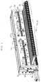
- an extrusion apparatus in the form of an extrusion die 20 includes a die entrance 22 into which molten thermoplastic is delivered by an extruder (not shown).
- the extrusion die 20 includes first and second die portions or halves 24, 26 which are held together by a plurality of body bolts 28 and a pair of end plate assemblies 30, 32 which are secured by bolts 34, 35 (seen in Figs. 1 and 5) to the die portions 24, 26.
- adjusters 36, 38 may be provided for positioning deckles which in turn limit the width of extruded product from the die 20.
- the die further includes a die exit 40 opposite the die entrance 22 and through which molten thermoplastic in sheet form is passed.
- the size of the die exit 40 may be adjusted by any suitable apparatus, for example by a sliding lip arrangement, a flexible lip arrangement movable by mechanical or thermally adjustable bolts (an example of the latter of which is disclosed in Nissel U.S. Patent No. 3,940,221, the disclosure of which is hereby incorporated by reference herein) or the like.
- a plurality of thermal actuators 42-1, 42-2 . . . 42-30 disposed along the length of the die portion 24 and secured thereto are a plurality of thermal actuators 42-1, 42-2 . . . 42-30, each of which is operable by a control unit 44 which is responsive to one or more sensed parameters, such as the temperatures of one or more portions of each actuator 42, as sensed by a plurality of thermocouples or other temperature sensors 45, and the sheet thickness just downstream of the die exit 40 at a plurality of spaced points across the width of the sheet, as detected by one or more thickness sensors 47.
- the control unit 44 includes a plurality of output lines 46-1, 46-2 . . . 46-30 which are coupled to input leads 48-1, 48-2 . . .
- the control unit 44 is capable of delivering controlled current levels using either a duty-cycle or pulse-width mode of operation or other regulation scheme to the thermal actuators 42-1, 42-2 . . . 42-30 either together or individually to accomplish flow tuning at a point inside the die 20, as noted in greater detail hereinafter.
- thermal actuators 42 are illustrated in the drawings (except Fig. 8, which is a fragmentary view as noted above) in connection with a die 20 having a 60 inch die exit width, it should be noted that a different number of actuators 42 may alternatively be used, as should be evident to one of ordinary skill in the art.
- the thermal actuators 42 are identical, and hence only the thermal actuator 42-15 seen in Fig. 7 will be described in detail.
- the thermal actuator 42-15 includes a housing member preferably in the form of a main tube 54 fabricated of a material having a low thermal coefficient of expansion, such as stainless steel marketed by Scientific Alloys, Inc. of Westerly, Rhode Island under the trademark Invar®, which is captured between first and second heads 56, 58, respectively.
- First through fourth tie rods 59 extend through the bores 60 in the head 56 and include threaded ends 61 that receive nuts 62 thereon. The nuts 62 bear against the head 56.
- the tie rods 59 include further threaded ends 63 that extend through bores 64 in the head 58 and are threaded into threaded bores 65 in the die half 24, respectively.
- the thermal actuator 42 is thus firmly secured to the die 20 and the main tube 54 is firmly seated in counterbores 66, 68 in the heads 56, 58, respectively.
- a translator member 70 in the form of a hollow column is disposed within the main tube 54 and includes first and second counterbores 72, 74 at opposite ends thereof.
- An electric resistance heating element 76 is disposed within the translator 70 between the counterbores 72, 74.
- a flexible resistance heating element may be wrapped around the outside of the translator 70, if desired.
- the counterbore 72 is threaded to accept a threaded end 78 of a mechanical adjuster 80 which extends through the head 56.
- the mechanical adjuster 80 includes a further threaded end 82 opposite the end 78 which is engaged by a nut 84 that in turn bears against a shouldered portion 86 of the head 56.
- a bore 89 extends through the head 56 and the nut 84 and the lead 48-15 extends through the bore 89 and is connected to the heating element 76.
- the counterbore 74 is likewise threaded and accepts a threaded end 90 of an elongate bolt or stud 92.
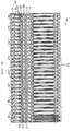
- the bolt or stud 92 extends through the head 58 and a bore 94 in the die half 24 and includes another threaded end 96 which extends into a threaded bore in a restrictor bar 100 which is in turn disposed in a recess 102.
- the recess 102 is formed by walls 104, 106 in the die body half 24, and is further defined by a surface 108 of a replaceable lip insert 110.
- the insert 110 is retained on the die body portion 24 by a plurality of bolts 112.
- a removable and replaceable flow insert 114 is disposed within a recess 116 in the die body portion 26 and is retained therein by bolts 118 (Fig. 8).
- the recesses 102 and 116 and the restrictor bar 100 and the insert 114 extend across the full width of the die 20 and are disposed opposite one another between the die entrance 22 and the die exit 40, and preferably between a manifold 120 and a melt well 122.
- the removable flow insert 114 includes a flow surface 124 which may be flat or curved or otherwise profiled to accomplish flow tuning of thermoplastic exiting the manifold 120 toward the die exit 40.
- thermal actuators 42 are operable by the control unit 44 to produce localized bends or deformations in a flow surface 126 of the restrictor bar to accomplish further flow tuning of the thermoplastic.
- relief cuts or slots 127 may be formed in a rear surface 128 of the restrictor bar 100 to render the bar 100 more flexible so that these localized deformations can be more easily produced therein.
- seals 129 may be provided in seal recesses to prevent the escape of extrudate past the restrictor bar 100.
- the heating element 76 heats up and causes the translator 70 to lengthen. This lengthening results in translation of the elongate bolt or stud 92 so that the flow surface 126 of the restrictor bar 100 extends more fully into the flow channel between the manifold 120 and the melt well 122. Because the main tube 54 is formed of a material having a low thermal coefficient of expansion, offsetting of the lengthening of the translator 70 that would otherwise occur due to expansion (and hence lengthening) of the main tube 54 is substantially avoided.
- the translator 70 cools, in turn resulting in a contraction of the elongate stud 92 and a withdrawal of a portion of the restrictor bar flow surface 126 from the channel between the manifold 120 and the melt well 122. In this way, local deformations can be formed in the flow surface 126 so that flow tuning can be precisely achieved.
- the flow surface 124 of the insert 114 may be flat; however, it may prove desirable to provide a different shape for the flow surface 124 so that less deformation of the flow surface 126 of the restrictor bar 100 would be required to produce a given flow effect than would otherwise be necessary. In this way, the overall stresses on the restrictor bar 100 can be reduced so that the bar 100 will be more flexible and capable of responding as necessary to the thermal actuators 42 to control flow.
- the flow surface 124 of the insert 114 may have a shape defined by a polynomial equation when viewed as seen in Fig.
- the flow surface 126 of the restrictor bar 100 may be adjusted by the thermal actuators 42 via the control unit 44 to have a uniform curved shape, for example a shape having a constant radius and thus defining a section of a circle.
- the flow surface 124 may have a uniform curved shape while the flow surface 126 may have a shape defined by a polynomial equation.
- control unit 44 The programming for the control unit 44 to produce currents of appropriate magnitude for the input leads 48-1, 48-2 . . . 48-30 is well within the capabilities of one of ordinary skill in the art. Any commercial control unit for controlling thermal die lip adjustment apparatus can be used, with only minor modifications to the programming thereof being necessary to account for variations in thermal response characteristics.
- One type of control unit is produced by Eurotherm, Inc. of Billerica, MA.
- the restrictor bar 100 and the insert 114 together accomplish flow tuning at an early point in the extrusion process well upstream of the die exit 40.
- the die exit 40 can be adjusted to have a constant gap opening dimension across the full width of the die 20 so that no flow tuning need be undertaken at such point. Because flow tuning takes place at an early point in the extrusion process and because the flow of extrudate is maintained in substantially constant shear conditions thereafter until the flow leaves the die, the flow is given an opportunity to fully develop and stabilize across the die width for as long as possible so that stresses resulting from the memory of the extrudate dissipate before the extrudate leaves the die. This results in reduced stress and distortion in the product.
- the present invention achieves other significant advantages.
Landscapes
- Engineering & Computer Science (AREA)
- Mechanical Engineering (AREA)
- Manufacturing & Machinery (AREA)
- Extrusion Moulding Of Plastics Or The Like (AREA)
Priority Applications (1)
| Application Number | Priority Date | Filing Date | Title |
|---|---|---|---|
| EP95115707A EP0767044A1 (fr) | 1995-10-04 | 1995-10-05 | Filière d'extrusion avec dispositif de correction de distribution de l'écoulement |
Applications Claiming Priority (3)
| Application Number | Priority Date | Filing Date | Title |
|---|---|---|---|
| US53929095A | 1995-10-04 | 1995-10-04 | |
| EP95115707A EP0767044A1 (fr) | 1995-10-04 | 1995-10-05 | Filière d'extrusion avec dispositif de correction de distribution de l'écoulement |
| 1997-12-23 |
Publications (1)
| Publication Number | Publication Date |
|---|---|
| EP0767044A1 true EP0767044A1 (fr) | 1997-04-09 |
Family
ID=26138846
Family Applications (1)
| Application Number | Title | Priority Date | Filing Date |
|---|---|---|---|
| EP95115707A Withdrawn EP0767044A1 (fr) | 1995-10-04 | 1995-10-05 | Filière d'extrusion avec dispositif de correction de distribution de l'écoulement |
Country Status (1)
| Country | Link |
|---|---|
| EP (1) | EP0767044A1 (fr) |
Cited By (5)
| Publication number | Priority date | Publication date | Assignee | Title |
|---|---|---|---|---|
| EP1181987A3 (fr) * | 2000-08-16 | 2003-04-16 | Beiersdorf Aktiengesellschaft | Procédés pour un revêtement au moins partiel de substrats |
| US9044894B2 (en) | 2011-06-07 | 2015-06-02 | 3M Innovative Properties Company | Slot die position adjustment and return to baseline |
| US9216535B2 (en) | 2011-06-07 | 2015-12-22 | 3M Innovative Properties Company | Slot die position adjustments to facilitate patterned products |
| US9579684B2 (en) | 2011-06-07 | 2017-02-28 | 3M Innovative Properties Company | Slot die position adjustment control |
| CN116600966A (zh) * | 2020-12-10 | 2023-08-15 | 诺信公司 | 用于挤出流体材料的设备 |
Citations (5)
| Publication number | Priority date | Publication date | Assignee | Title |
|---|---|---|---|---|
| US3859032A (en) * | 1973-11-28 | 1975-01-07 | Extrusion Dies Inc | Adjusting mechanism for restrictor bar of a slot extrusion die |
| JPS60165218A (ja) * | 1984-02-08 | 1985-08-28 | Johoku Seikosho:Kk | Tダイ |
| EP0317545A2 (fr) * | 1987-11-17 | 1989-05-24 | Monsanto Company | Procédé de fabrication d'une feuille de polyvinyl butyral |
| JPH0376611A (ja) * | 1989-08-21 | 1991-04-02 | Asahi Chem Ind Co Ltd | 合成樹脂シート成形プロセスの制御方法及びその装置 |
| JPH05162188A (ja) * | 1991-12-12 | 1993-06-29 | Mitsubishi Heavy Ind Ltd | ダイリップ制御装置 |
-
1995
- 1995-10-05 EP EP95115707A patent/EP0767044A1/fr not_active Withdrawn
Patent Citations (5)
| Publication number | Priority date | Publication date | Assignee | Title |
|---|---|---|---|---|
| US3859032A (en) * | 1973-11-28 | 1975-01-07 | Extrusion Dies Inc | Adjusting mechanism for restrictor bar of a slot extrusion die |
| JPS60165218A (ja) * | 1984-02-08 | 1985-08-28 | Johoku Seikosho:Kk | Tダイ |
| EP0317545A2 (fr) * | 1987-11-17 | 1989-05-24 | Monsanto Company | Procédé de fabrication d'une feuille de polyvinyl butyral |
| JPH0376611A (ja) * | 1989-08-21 | 1991-04-02 | Asahi Chem Ind Co Ltd | 合成樹脂シート成形プロセスの制御方法及びその装置 |
| JPH05162188A (ja) * | 1991-12-12 | 1993-06-29 | Mitsubishi Heavy Ind Ltd | ダイリップ制御装置 |
Non-Patent Citations (4)
| Title |
|---|
| FRANK R. NISSEL: "Recent Developments in Sheet Extrusion Systems", SPE JOURNAL, vol. 26, no. 1, pages 25 - 28 * |
| PATENT ABSTRACTS OF JAPAN vol. 009, no. 333 (M - 443) 27 December 1985 (1985-12-27) * |
| PATENT ABSTRACTS OF JAPAN vol. 015, no. 239 (M - 1126) 20 June 1991 (1991-06-20) * |
| PATENT ABSTRACTS OF JAPAN vol. 017, no. 565 (M - 1495) 13 October 1993 (1993-10-13) * |
Cited By (7)
| Publication number | Priority date | Publication date | Assignee | Title |
|---|---|---|---|---|
| EP1181987A3 (fr) * | 2000-08-16 | 2003-04-16 | Beiersdorf Aktiengesellschaft | Procédés pour un revêtement au moins partiel de substrats |
| US9044894B2 (en) | 2011-06-07 | 2015-06-02 | 3M Innovative Properties Company | Slot die position adjustment and return to baseline |
| US9216535B2 (en) | 2011-06-07 | 2015-12-22 | 3M Innovative Properties Company | Slot die position adjustments to facilitate patterned products |
| US9579684B2 (en) | 2011-06-07 | 2017-02-28 | 3M Innovative Properties Company | Slot die position adjustment control |
| US9744708B2 (en) | 2011-06-07 | 2017-08-29 | 3M Innovative Properties Company | Slot die position adjustment and return to baseline |
| CN116600966A (zh) * | 2020-12-10 | 2023-08-15 | 诺信公司 | 用于挤出流体材料的设备 |
| US12558830B2 (en) | 2020-12-10 | 2026-02-24 | Nordson Corporation | Apparatus and method for extruding a fluid material |
Similar Documents
| Publication | Publication Date | Title |
|---|---|---|
| US3680997A (en) | Extrusion strip die for thermoplastic sheet | |
| EP0646450B1 (fr) | Appareil pour l'extrusion de matières thermoplastiques | |
| CA2231533C (fr) | Dispositif de delimitation variable d'un canal d'ecoulement plat et procede d'extraction d'une bande de matiere a geometrie variable. | |
| JPS591220A (ja) | 多成分連続フイルムダイ | |
| EP0256490B1 (fr) | Filière réglable par chauffage | |
| AU696746B2 (en) | Improvements in or relating to the manufacture of extrusion dies | |
| JP3522291B2 (ja) | 熱可塑性プラスチックから平らな帯材を製造するための押出しダイ | |
| EP0767044A1 (fr) | Filière d'extrusion avec dispositif de correction de distribution de l'écoulement | |
| US7056112B2 (en) | Extrusion die and method for using the same | |
| US20210001530A1 (en) | Extruder and method for extruding cord reinforced tire components | |
| US5511962A (en) | Extrusion die | |
| JP3662169B2 (ja) | 冷却ノズル法で熱可塑性合成樹脂製の中空室付き異形材を製造する方法と装置 | |
| US20080057148A1 (en) | Extrusion die for forming polymeric foam sheets | |
| JPH04135824A (ja) | 中空プレートを製作するための押出しノズル | |
| US6352424B1 (en) | Extrusion die membrane assembly | |
| US20050006810A1 (en) | Method and system for dual co-extrusion | |
| JPH05441A (ja) | 押出装置 | |
| DE3503721A1 (de) | Breitschlitzduese zum extrudieren eines thermoplastischen kunststoffes | |
| US6106268A (en) | Internal deckle for film extrusion dies | |
| JP2000006227A (ja) | 押出成形用ダイ | |
| EP1064140A1 (fr) | Membrane pour filiere d'extrusion | |
| JPH09327853A (ja) | 押出しダイス | |
| US7104778B2 (en) | International die deckle with flow control | |
| JPS59114027A (ja) | 押出成形用ダイ | |
| JPH08187763A (ja) | シート製品押出し用可変幅ダイ |
Legal Events
| Date | Code | Title | Description |
|---|---|---|---|
| PUAI | Public reference made under article 153(3) epc to a published international application that has entered the european phase |
Free format text: ORIGINAL CODE: 0009012 |
|
| AK | Designated contracting states |
Kind code of ref document: A1 Designated state(s): BE CH DE FR GB IT LI NL SE |
|
| 17P | Request for examination filed |
Effective date: 19970605 |
|
| STAA | Information on the status of an ep patent application or granted ep patent |
Free format text: STATUS: THE APPLICATION IS DEEMED TO BE WITHDRAWN |
|
| 18D | Application deemed to be withdrawn |
Effective date: 19990504 |