EP0768941B1 - Method and apparatus for producing bodies of consolidated particulate material, and product produced thereby - Google Patents
Method and apparatus for producing bodies of consolidated particulate material, and product produced thereby Download PDFInfo
- Publication number
- EP0768941B1 EP0768941B1 EP95924873A EP95924873A EP0768941B1 EP 0768941 B1 EP0768941 B1 EP 0768941B1 EP 95924873 A EP95924873 A EP 95924873A EP 95924873 A EP95924873 A EP 95924873A EP 0768941 B1 EP0768941 B1 EP 0768941B1
- Authority
- EP
- European Patent Office
- Prior art keywords
- pressure
- suspension
- liquid
- mould
- flowable
- Prior art date
- Legal status (The legal status is an assumption and is not a legal conclusion. Google has not performed a legal analysis and makes no representation as to the accuracy of the status listed.)
- Expired - Lifetime
Links
- 238000000034 method Methods 0.000 title claims abstract description 50
- 239000011236 particulate material Substances 0.000 title claims abstract 7
- 239000007788 liquid Substances 0.000 claims abstract description 34
- 230000009969 flowable effect Effects 0.000 claims abstract description 31
- 238000007596 consolidation process Methods 0.000 claims abstract description 16
- 239000002245 particle Substances 0.000 claims abstract description 16
- 239000002002 slurry Substances 0.000 claims abstract description 15
- 239000007787 solid Substances 0.000 claims abstract description 3
- 238000001125 extrusion Methods 0.000 claims abstract 10
- 238000007493 shaping process Methods 0.000 claims abstract 3
- 239000000725 suspension Substances 0.000 claims description 41
- 239000000047 product Substances 0.000 claims description 34
- 239000000463 material Substances 0.000 claims description 32
- 238000000465 moulding Methods 0.000 claims description 13
- 238000011144 upstream manufacturing Methods 0.000 claims description 10
- 230000000694 effects Effects 0.000 claims description 9
- 239000011159 matrix material Substances 0.000 claims description 9
- 238000006243 chemical reaction Methods 0.000 claims description 5
- 239000002131 composite material Substances 0.000 claims description 5
- 239000000835 fiber Substances 0.000 claims description 4
- 238000005086 pumping Methods 0.000 claims description 4
- 239000004927 clay Substances 0.000 claims description 3
- 239000011396 hydraulic cement Substances 0.000 claims description 2
- 239000000203 mixture Substances 0.000 claims description 2
- 230000003467 diminishing effect Effects 0.000 claims 3
- 239000011148 porous material Substances 0.000 claims 2
- OKTJSMMVPCPJKN-UHFFFAOYSA-N Carbon Chemical compound [C] OKTJSMMVPCPJKN-UHFFFAOYSA-N 0.000 claims 1
- 229920003043 Cellulose fiber Polymers 0.000 claims 1
- 239000004743 Polypropylene Substances 0.000 claims 1
- 229910000831 Steel Inorganic materials 0.000 claims 1
- 239000000378 calcium silicate Substances 0.000 claims 1
- 229960003340 calcium silicate Drugs 0.000 claims 1
- 229910052918 calcium silicate Inorganic materials 0.000 claims 1
- 235000012241 calcium silicate Nutrition 0.000 claims 1
- OYACROKNLOSFPA-UHFFFAOYSA-N calcium;dioxido(oxo)silane Chemical compound [Ca+2].[O-][Si]([O-])=O OYACROKNLOSFPA-UHFFFAOYSA-N 0.000 claims 1
- 229910052799 carbon Inorganic materials 0.000 claims 1
- 239000003365 glass fiber Substances 0.000 claims 1
- 229910052602 gypsum Inorganic materials 0.000 claims 1
- 239000010440 gypsum Substances 0.000 claims 1
- 238000000265 homogenisation Methods 0.000 claims 1
- 238000004519 manufacturing process Methods 0.000 claims 1
- 229920000098 polyolefin Polymers 0.000 claims 1
- -1 polypropylene Polymers 0.000 claims 1
- 229920001155 polypropylene Polymers 0.000 claims 1
- 230000002787 reinforcement Effects 0.000 claims 1
- 239000012265 solid product Substances 0.000 claims 1
- 239000010959 steel Substances 0.000 claims 1
- XLYOFNOQVPJJNP-UHFFFAOYSA-N water Substances O XLYOFNOQVPJJNP-UHFFFAOYSA-N 0.000 abstract description 9
- 239000007795 chemical reaction product Substances 0.000 description 5
- 238000003825 pressing Methods 0.000 description 5
- 238000005266 casting Methods 0.000 description 3
- 230000001747 exhibiting effect Effects 0.000 description 3
- 230000015572 biosynthetic process Effects 0.000 description 2
- 235000012438 extruded product Nutrition 0.000 description 2
- 239000000843 powder Substances 0.000 description 2
- 238000005482 strain hardening Methods 0.000 description 2
- 239000011398 Portland cement Substances 0.000 description 1
- 239000004568 cement Substances 0.000 description 1
- 238000009760 electrical discharge machining Methods 0.000 description 1
- 238000010304 firing Methods 0.000 description 1
- 230000005484 gravity Effects 0.000 description 1
- 230000036571 hydration Effects 0.000 description 1
- 238000006703 hydration reaction Methods 0.000 description 1
- 230000002706 hydrostatic effect Effects 0.000 description 1
- 239000002184 metal Substances 0.000 description 1
- 238000009931 pascalization Methods 0.000 description 1
- 230000035699 permeability Effects 0.000 description 1
- 230000000704 physical effect Effects 0.000 description 1
- 230000002250 progressing effect Effects 0.000 description 1
- 239000004576 sand Substances 0.000 description 1
- 239000011343 solid material Substances 0.000 description 1
Images

Classifications
-
- B—PERFORMING OPERATIONS; TRANSPORTING
- B28—WORKING CEMENT, CLAY, OR STONE
- B28B—SHAPING CLAY OR OTHER CERAMIC COMPOSITIONS; SHAPING SLAG; SHAPING MIXTURES CONTAINING CEMENTITIOUS MATERIAL, e.g. PLASTER
- B28B7/00—Moulds; Cores; Mandrels
- B28B7/40—Moulds; Cores; Mandrels characterised by means for modifying the properties of the moulding material
- B28B7/46—Moulds; Cores; Mandrels characterised by means for modifying the properties of the moulding material for humidifying or dehumidifying
-
- B—PERFORMING OPERATIONS; TRANSPORTING
- B28—WORKING CEMENT, CLAY, OR STONE
- B28B—SHAPING CLAY OR OTHER CERAMIC COMPOSITIONS; SHAPING SLAG; SHAPING MIXTURES CONTAINING CEMENTITIOUS MATERIAL, e.g. PLASTER
- B28B3/00—Producing shaped articles from the material by using presses; Presses specially adapted therefor
- B28B3/20—Producing shaped articles from the material by using presses; Presses specially adapted therefor wherein the material is extruded
- B28B3/205—Producing shaped articles from the material by using presses; Presses specially adapted therefor wherein the material is extruded using vibrations
Definitions
- the present invention relates to a method of the kind set forth in the preamble of claim 1.
- a method of this kind is disclosed in BE-A-653,349 and SE-B-304,711 (both based on FR priority application No. 955,561 of 29 November 1963).
- an unhardened mixture comprising hydraulic cement and aggregate material (sand and gravel) with surplus water is compressed in an extruder of constant cross-sectional shape by means of a reciprocating piston, and in the terminal part of said extruder, the walls of which are suitably perforated, part of the water is removed by applying a vacuum to the outside of said walls, all this taking place while the material is moving slowly through the extruder.
- the pressure differential that can be produced by said vacuum arrangement is at the highest of the order of one bar.
- the reciprocating piston does, admittedly, exert a certain force, thus causing a corresponding increase in the pressure differential effecting the de-watering, but if sufficuently increased, this force will simply push the material out of the extruder, as no cdunter-force is provided to prevent this.
- the high pressure differential produced by applying a high positive pressure to the inside of the perforated walls in the mould, will cause so much of the liquid between the particles to be expelled and the particles to come into such mutual engagement, that a shaped body having a considerable mechanical strength is produced, and as the slurry has already been homogenized, the shaped body will have a uniform structure throughout its volume.
- the final part of the pressing process when no further water can be squeezed out, can be characterized as powder pressing.
- the process as such commences in the form of high-pressure slurry pumping in one end of the mould and terminates as a powder-pressing process steadily progressing from the other end of the mould.
- the low-viscosity suspension will have no difficulty in flowing out into all nooks and crannies of the mould, and any air having been trapped during the filling-up of the mould will leave the mould cavity through its perforations together with the surplus liquid.
- the finished press-moulded object will constitute an accurate replica of the internal surfaces of the mould, and since the composite material already has solidified in the mould in the same moment as all surplus water has been squeezed out and mutual contact between the solid-matter particles has been achieved, it is now possible to remove the moulded object from the mould immediately-just as with any other powder-pressing method - since this object is now fully rigid and self-supporting and requires no more than being allowed to harden completely by hydration in a suitable manner.
- the perforations or holes in the walls of the moulds should, of course, be exstremely fine, so that the water, but not the solid-matter particles may escape from the mould, but since water molecules are extremely small (approximately 20 ⁇ ), this should not be a problem.
- the end product made by proceeding according to one of the embodiments of the method according to the invention is characterized by being exceptionally dense and with an absolute minimum of porosity and being highly homogeneous, and by, in the fully-hardened condition, to possess valuable physical properties comprising an optimum combination of strength and toughness.
- the mixing process is carried out with an arbitrary surplus amount of liquid, and the concentration of the material subsequently during the casting or moulding process is increased without “demixing" taking place, until no more liquid can be squeezed out from the confined material, it is possible in this case to achieve a considerably higher concentration of fibres in the end product than by using any other known moulding or casting principle, still with the fibres lying fully dispersed and well distributed and oriented throughout the product.
- the particles are also pressed firmly against all fibre surfaces - in certain cases even into the surfaces of the fibres - resulting in optimum bond between of the fibre and the matrix material and hence optimum fibre effect in the end product.
- fibres and matrix material "grow together" in a manner not being known from other casting or moulding processes, and after having fully hardened, the end product possesses unique physical proporties.
- a correctly made BMC material produced according to the present invention will have a tensile stress-strain curve exhibiting so-called strain hardening, in which the tensile stress continues to increase - without any formation of visible or harmful cracks - even right up to a strain of 1-2% or more.
- strainability (elasticity or flexibility if so preferred) of the matrix material has, by extreme utilization of the admixed fibres, been increased by a factor of 100 or more - and this without causing any damage to the composite material.
- the mechanism behind the dramatically increased strainability of the composite material is that the internal rupturing of the matrix material between the fibres due to tensile straining occurs in a different manner than in similar non-reinforced material, as, on a microscopic level, an evenly distributed pattern of extremely fine and short microscopic cracks are formed, increasing in number with increased straining of the material; these microscopic cracks are, however, so small that they may be stopped or blocked by the surrounding fibres, and for this reason they cause no dramatic damage to the material as such.
- the present invention also relates to an apparatus for carrying out the method of the invention.
- This apparatus is of the kind set forth in the preamble of claim 17, and according to the present invention, it also comprises the features set forth in the characterizing clause of this claim 17.
- the invention relates to a product, such as set forth in claim 27.
- Figure 1 shows the parts of an extruder essential to the invention, specially designed for producing tubular products, it being obvious that an extruder based on the same principles could also be used for extruding products with other cross-sectional shapes, such as flat or corrugated sheets or profiled stock of various cross-sectional shapes.
- the parts of the extruder shown comprise an outer part 1, an inner part 2, a plurality of nozzles or slits 3 for draining-off liquid, as well as a pressure-regulating chamber 5.
- the extruder is divided into four consecutive sections, i.e.
- Figure 1 shows a further section, designated the exit section E, in which the extruded product leaves the extruder.
- Figure 1 shows the above-mentioned sections as quite distinct from each other, but in practice, two or more sections may overlap to a greater or lesser degree.
- the nozzles 3, shown in Figure 1 as solely being present in the drainage and consolidation section C may well also extend along at least a part of the solid-friction section D.
- a flowable suspension containing the requisite amounts of powder, liquid (normally water) and possibly further components flows into the flow section B.
- the suspension supplied to the extruder comprises a surplus of water or other liquid, making it possible to achieve a good and homogeneous intermixing of the components of the suspension, that may have a consistency ranging from a thin slurry to a thick paste.
- the mixing process may be carried out in a manner known per se, i.e. by using a high-performance mixer producing a paste-like particle suspension with the desired flowability, prior to supplying the latter to the inlet section A of the extruder by means of a high-pressure pump of a type capable of pumping material of this kind.
- the suspension flows in the forward direction through the flow section B.
- the cross-sectional shape of the shaped product in this section B and the subsequent drainage and consolidation section C is determined by the internal shape of the outer part 1 and the external shape of the inner part 2.
- surplus liquid is drained off, and the suspension is consolidated to form a solid material with direct contact between the individual particles throughout the product, as substantially all surplus liquid, i.e. substantially all liquid not remaining to occupy the interspaces between the closely packed particles in direct mutual contact, is removed.
- This draining-off function is caused by the pressure differential across the outer part 1 in the drainage and consolidation section C being applied to the nozzles or slits 3.
- the pressure differential constitutes the difference between on the one hand the hydrostatic pressure in the suspension in the flow section B and part of the drainage and consolidation section C, which may lie in the range of 20-400 bar, and on the other hand the pressure within the pressure-regulating chamber 5, that may be atmospheric pressure or somewhat higher or lower, as will be explained below.
- the high hydrostatic pressure reigning in the flow section B and at least the adjacent part of the drainage and consolidation section C can only be maintained, if the part of the extruder downstream of the drainage and consolidation section C comprises some means of obstructing flow.
- these means are provided by the non-flowable extruded product resulting from the drainage and consolidation described above, being present in the solid-friction section D.
- the friction between the product 4 and the walls of the outer part 1 and the inner part 2 in contact with it is sufficient to provide a reaction force of substantially the same magnitude as the oppositely acting hydraulic force resulting from the hydraulic pressure upstream of the solid-friction section D.
- the supply pressure and the pressure in the pressure-regulating chamber 5 are attuned to each other and to the friction referred to in the solid-friction section D so as to allow the product 4 to advance at a suitable speed.
- reaction force referred to above When starting-up the process, it is necessary to provide the reaction force referred to above by separate means, as the non-flowable product part has not yet been formed in the solid-friction section D.
- This may suitably be achieved by inserting a reaction-force plug (not shown) into the downstream end of the interspace between the outer part 1 and the inner part 2 so as to effect a temporary closure.
- a first method of reducing the effect of friction between the consolidated material and the walls of the extruder consists in subjecting the exit portion of the extruder or a part of same to mechanical vibrations.
- the frequency of these vibrations may lie in the interval 10-400 Hz, while the interval 20-200 Hz is preferred and the interval 50-150 Hz is more preferred.
- Another method of reducing the effect of the high friction referred to above is to subject the flowable suspension upstream of the consolidated product to pressure variations, so that periods with a first, lower pressure alternate with second, shorter periods with a second, higher pressure, said second pressure being approximately 1.5-8, preferably 2-4 times greater than said first pressure.
- a third method of reducing the effect of the high friction referred to above is to vary the pressure in the pressure-regulating chamber 5, so that the surface of the product in some periods is subjected to reduced pressure to support the draining-off process, and in other periods being subjected to a high-pressure to reduce the friction between the product and the extruder walls.
- a fourth method of reducing the effect of the high friction referred to above is based on using an extruder, in which a first part, i.e. the outer part 1 shown in Figure 1, is capable of being reciprocated in the longitudinal direction relative to another part of the extruder, e.g. the inner parts 2. With such relative movement, that may e.g. be effected by using a crank mechanism (not shown), the product 4 will be made to "walk" stepwise in the downstream direction.
- the stepwise "walking" movement of the product is achieved through the following mechanism:
- both parts of the extruder are stationary, the resulting frictional force between the product and the extruder walls will act in the upstream direction with a magnitude always equal to the resulting force on the product in the downstream direction from the pressure in the flowable suspension.
- the friction stresses between the product and the movable extruder wall will change direction and result in a frictional force in the downstream direction.
- an extruder working according to this principle should be designed taking into consideration the cross-sectional area of the product, the working pressure in the flowable suspension and the size and frictional characteristics of on the one hand the surface between the stationary part of the extruder and the product and on the other hand the surface between the movable part of the extruder and the product.
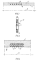
- Figure 2 shows one example of how the requisite permeability of the extruder wall in the drainage and consolidation section C may be achieved.
- a number of holes 6 have been drilled into the outer part 1 from the outside.
- the holes 6 only extend to within approx. 1 mm from the inside wall 7.
- a plurality of extremely fine perforations 8 with transverse dimensions of the order of 0.001-0.01 mm extend through the respective drilled holes 6.
- the perforations 8 may be produced by means of e.g. spark erosion or by using a laser beam.
- Figure 2 also shows the central axis 9 of the extruder.
- Figures 3 and 4 Another way of providing the requisite openings in the drainage and consolidation section C is shown in Figures 3 and 4.
- Figure 3 shows a ring to be used for this purpose
- Figure 4 shows how a number of such rings are assembled to form a number of slits constituting said openings.
- the ring 12 shown in Figure 3 comprises an inner periphery 10 and an outer periphery 11.
- the width b 1 of the inner periphery 10 is a trifle, typically approximately 0.001-0.01 mm, less than the width b 2 of the outer periphery 11.
- slits 3 will be formed between them with a width of typically approximately 0.001-0.01 mm in the drainage and consolidation section C, through which the liquid to be drained off may escape.
- Figure 4 shows a number of rings 12 of the kind shown in Figure 3 mounted in the axial direction in the outer part 1 of the extruder, so that the inner peripheries 10 of the rings are aligned with the inside surface of the outer part 1 of the extruder.
- Figure 4 shows the outer parts 1 and a plurality, in this case a total of six, individual rings 12 with the drainage slits 3 between the rings. The central axis 9 of the extruder will also be seen.
Landscapes
- Engineering & Computer Science (AREA)
- Manufacturing & Machinery (AREA)
- Chemical & Material Sciences (AREA)
- Ceramic Engineering (AREA)
- Mechanical Engineering (AREA)
- Press-Shaping Or Shaping Using Conveyers (AREA)
- Physical Or Chemical Processes And Apparatus (AREA)
- Formation And Processing Of Food Products (AREA)
- Other Resins Obtained By Reactions Not Involving Carbon-To-Carbon Unsaturated Bonds (AREA)
- Paints Or Removers (AREA)
Applications Claiming Priority (4)
| Application Number | Priority Date | Filing Date | Title |
|---|---|---|---|
| DK83094 | 1994-07-08 | ||
| DK830/94 | 1994-07-08 | ||
| DK83094 | 1994-07-08 | ||
| PCT/DK1995/000296 WO1996001726A1 (en) | 1994-07-08 | 1995-07-07 | Method and apparatus for producing bodies of consolidated particulate material, and product produced thereby |
Publications (2)
| Publication Number | Publication Date |
|---|---|
| EP0768941A1 EP0768941A1 (en) | 1997-04-23 |
| EP0768941B1 true EP0768941B1 (en) | 2000-01-19 |
Family
ID=8098039
Family Applications (1)
| Application Number | Title | Priority Date | Filing Date |
|---|---|---|---|
| EP95924873A Expired - Lifetime EP0768941B1 (en) | 1994-07-08 | 1995-07-07 | Method and apparatus for producing bodies of consolidated particulate material, and product produced thereby |
Country Status (8)
| Country | Link |
|---|---|
| US (3) | US6398998B1 (da) |
| EP (1) | EP0768941B1 (da) |
| JP (1) | JPH10502308A (da) |
| AT (1) | ATE188898T1 (da) |
| AU (2) | AU2921595A (da) |
| DE (1) | DE69514662T2 (da) |
| DK (1) | DK0768941T3 (da) |
| WO (2) | WO1996001727A1 (da) |
Families Citing this family (21)
| Publication number | Priority date | Publication date | Assignee | Title |
|---|---|---|---|---|
| US7172714B2 (en) * | 1999-01-11 | 2007-02-06 | 2Phase Technologies, Inc. | Use of state-change materials in reformable shapes, templates or tooling |
| US6780352B2 (en) * | 1999-01-11 | 2004-08-24 | 2Phase Technologies, Inc. | Use of state-change materials in reformable shapes, templates or tooling |
| US6694690B2 (en) * | 2000-07-10 | 2004-02-24 | The Regents Of The University Of Michigan | Concrete constructions employing the use of a ductile strip |
| EP1400337B1 (de) * | 2002-09-20 | 2007-08-22 | Basf Aktiengesellschaft | Vorrichtung und Verfahren zum Extrudieren von Thermoplasten und Verwendung davon. |
| CA2545417A1 (en) * | 2003-11-19 | 2005-06-02 | Rocla Pty Ltd | Cementitious pipes |
| AU2004291212B2 (en) * | 2003-11-19 | 2010-06-17 | 3H Inventors Aps | A process and apparatus for green body extrusion |
| JP2007511392A (ja) * | 2003-11-19 | 2007-05-10 | 3エイチ・インベンターズ・エーピーエス | グリーン体押出しの方法及び装置 |
| AU2005289384B2 (en) * | 2004-09-29 | 2010-05-13 | 3H Inventors Aps | Method of extrusion of particulate pastes or suspensions |
| EP1793973A4 (en) * | 2004-09-29 | 2009-07-15 | 3H Inventors Aps | PROCESS FOR EXTRUSION OF PARTICULATE PASTA OR SUSPENSION |
| US7968047B2 (en) * | 2005-02-10 | 2011-06-28 | Wahl Refractory Solutions, Llc | Blaster nozzle |
| ITMI20052356A1 (it) * | 2005-12-09 | 2007-06-10 | Italcementi Spa | Processo per la produzione di tubazioni in materiale cementizio a sezione circolare |
| WO2016015128A1 (en) * | 2014-07-29 | 2016-02-04 | 161508 Canada Inc. | System and process for molding of parts made of fiber cement |
| US9610476B1 (en) | 2016-05-02 | 2017-04-04 | Bao Tran | Smart sport device |
| US10299722B1 (en) | 2016-02-03 | 2019-05-28 | Bao Tran | Systems and methods for mass customization |
| US9996981B1 (en) | 2016-03-07 | 2018-06-12 | Bao Tran | Augmented reality system |
| US9460557B1 (en) | 2016-03-07 | 2016-10-04 | Bao Tran | Systems and methods for footwear fitting |
| US10293565B1 (en) | 2016-04-12 | 2019-05-21 | Bao Tran | Systems and methods for mass customization |
| US10022614B1 (en) | 2016-05-02 | 2018-07-17 | Bao Tran | Smart device |
| US9597567B1 (en) | 2016-05-02 | 2017-03-21 | Bao Tran | Smart sport device |
| US9964134B1 (en) | 2016-05-03 | 2018-05-08 | Bao Tran | Smart IOT sensor having an elongated stress sensor |
| US9615066B1 (en) | 2016-05-03 | 2017-04-04 | Bao Tran | Smart lighting and city sensor |
Family Cites Families (42)
| Publication number | Priority date | Publication date | Assignee | Title |
|---|---|---|---|---|
| US1693429A (en) * | 1926-07-02 | 1928-11-27 | Ohio Brass Co | Method of casting |
| US2026782A (en) * | 1931-04-03 | 1936-01-07 | Locke Insulator Corp | Clay homogenizing method and apparatus |
| US1989409A (en) * | 1932-05-24 | 1935-01-29 | Viber Company Ltd | Method and apparatus for compacting and dewatering cementitious materials |
| GB544275A (en) * | 1940-03-08 | 1942-04-07 | Niels Steensen | Improved process for the manufacture of castings of artificial stone such as concrete |
| US2408627A (en) * | 1943-10-11 | 1946-10-01 | Lee B Green | Apparatus for extruding |
| US2549886A (en) * | 1947-07-18 | 1951-04-24 | United Aircraft Corp | Folding rotor blade |
| US2694349A (en) * | 1949-06-25 | 1954-11-16 | Crane Co | Method for producing cement pipes |
| US2549686A (en) | 1949-09-16 | 1951-04-17 | Crane Co | Apparatus for the extrusion of pipe |
| DE955210C (de) | 1950-11-04 | 1957-02-21 | Wessel Werk A G | Verfahren zum Strangpressen von keramischen Massen |
| DE954039C (de) | 1952-06-11 | 1956-12-13 | Siemens Ag | Vakuumstrangpresse fuer keramische und andere bildsame Massen ohne Vorschuborgan |
| US2836848A (en) * | 1953-03-27 | 1958-06-03 | Owens Illinois Glass Co | Method and apparatus for forming calcium silicate products |
| FR1384863A (fr) * | 1963-11-29 | 1965-01-08 | Procédé de fabrication en série de corps creux en béton et appareillage pour la mise en oeuvre de ce procédé | |
| US3619429A (en) * | 1969-06-04 | 1971-11-09 | Yawata Welding Electrode Co | Method for the uniform extrusion coating of welding flux compositions |
| US3926541A (en) * | 1970-06-29 | 1975-12-16 | Frederick M Hewitt | Extruder with interacting auger and care means |
| US3686070A (en) * | 1971-05-12 | 1972-08-22 | John S Williams | Production of fibrous logs by continuously passing slurry through a forming chamber |
| CH524451A (de) * | 1971-06-24 | 1972-06-30 | Alusuisse | Verfahren und Vorrichtung zum kontinuierlichen Herstellen eines Stranges aus kleinteiliger Masse |
| US3994639A (en) * | 1973-01-11 | 1976-11-30 | Hewitt Frederick M | Apparatus for extruding concrete |
| DE2319254B2 (de) * | 1973-04-16 | 1978-05-03 | Vereinigte Aluminium-Werke Ag, 5300 Bonn | Vorrichtung zur Verdichtung und Formgebung von Kunstkohlemasse |
| US4067676A (en) * | 1974-12-19 | 1978-01-10 | Hewitt Frederick M | Apparatus for extruding reinforced concrete |
| FR2321991A1 (fr) * | 1975-08-29 | 1977-03-25 | Atiwell Ronald | Procede et dispositif de moulage et d'extrusion |
| US4133619A (en) * | 1976-09-10 | 1979-01-09 | The Flexicore Co., Inc. | Extrusion casting apparatus |
| US4252759A (en) * | 1979-04-11 | 1981-02-24 | Massachusetts Institute Of Technology | Cross flow filtration molding method |
| US4446094A (en) * | 1982-09-23 | 1984-05-01 | Welding Engineers, Inc. | Apparatus and method for extracting fluid from an extruded material |
| US4490104A (en) * | 1982-11-22 | 1984-12-25 | Borg-Warner Chemicals, Inc. | Apparatus for separating a low viscosity material from a high _viscosity material |
| FI843544A0 (fi) * | 1984-09-10 | 1984-09-10 | Rakennusvalmiste Oy | Glidgjutmaskin foer framstaellning av betongelement. |
| JPS62253406A (ja) * | 1986-04-26 | 1987-11-05 | 大倉工業株式会社 | 補強繊維を配向させるセメント含有w/o型エマルジヨンの押出成形方法及びその装置 |
| JPS6342803A (ja) * | 1986-08-08 | 1988-02-24 | 東陶機器株式会社 | 鋳込み成形法及び装置 |
| HU199363B (en) * | 1987-05-05 | 1990-02-28 | Fallo Fakombinat | Process for production and equipment for elements especially constructing elements from afterhardening materials |
| JPH01175803A (ja) | 1987-12-29 | 1989-07-12 | Achilles Corp | 射出成形靴の製造装置 |
| JPH069845B2 (ja) * | 1988-11-24 | 1994-02-09 | 出光興産株式会社 | 押出成形方法とその装置 |
| GB8900434D0 (en) * | 1989-01-10 | 1989-03-08 | Allan Peter S | Improvements in or relating to methods and apparatus for the continuous formation of an extruded product |
| US4943402A (en) * | 1989-10-31 | 1990-07-24 | E. I. Du Pont De Nemours And Company | Process for removing chloroprene dimers from polychloroprene |
| US5232649A (en) * | 1990-10-31 | 1993-08-03 | Werner & Pfleiderer | Method of removing liquids from solids |
| US5249948A (en) * | 1991-04-08 | 1993-10-05 | Koslow Technologies Corporation | Apparatus for the continuous extrusion of solid articles |
| JPH05228913A (ja) * | 1991-07-26 | 1993-09-07 | Sumitomo Electric Ind Ltd | セラミックスの成形法および装置 |
| JPH05208439A (ja) * | 1991-12-03 | 1993-08-20 | Sekisui Chem Co Ltd | 押出成形品の製造方法および製造装置 |
| JPH05200831A (ja) * | 1992-01-29 | 1993-08-10 | Mitsubishi Plastics Ind Ltd | 押出用口金 |
| WO1993020990A1 (en) | 1992-04-14 | 1993-10-28 | Assadollah Redjvani | A method of continuous concrete casting by extrusion |
| US5545297A (en) * | 1992-08-11 | 1996-08-13 | E. Khashoggi Industries | Methods for continuously placing filaments within hydraulically settable compositions being extruded into articles of manufacture |
| US5498383A (en) * | 1994-05-18 | 1996-03-12 | National Research Council Of Canada | Slip casting process and apparatus for producing graded materials |
| US5529734A (en) * | 1994-08-09 | 1996-06-25 | E. I. Du Pont De Nemours And Company | Process for making and collecting continuous fibers in the form of a rod-shaped batt |
| JP3014665B2 (ja) * | 1997-09-05 | 2000-02-28 | デルマール株式会社 | 食品押出成型装置および食品押出成型方法 |
-
1995
- 1995-07-07 DK DK95924873T patent/DK0768941T3/da active
- 1995-07-07 JP JP8504065A patent/JPH10502308A/ja active Pending
- 1995-07-07 AU AU29215/95A patent/AU2921595A/en not_active Abandoned
- 1995-07-07 WO PCT/DK1995/000297 patent/WO1996001727A1/en not_active Ceased
- 1995-07-07 AT AT95924873T patent/ATE188898T1/de not_active IP Right Cessation
- 1995-07-07 AU AU29216/95A patent/AU2921695A/en not_active Abandoned
- 1995-07-07 US US08/765,905 patent/US6398998B1/en not_active Expired - Fee Related
- 1995-07-07 EP EP95924873A patent/EP0768941B1/en not_active Expired - Lifetime
- 1995-07-07 DE DE69514662T patent/DE69514662T2/de not_active Expired - Lifetime
- 1995-07-07 WO PCT/DK1995/000296 patent/WO1996001726A1/en not_active Ceased
-
2002
- 2002-06-03 US US10/158,935 patent/US7244115B2/en not_active Expired - Fee Related
- 2002-06-03 US US10/158,940 patent/US20020140123A1/en not_active Abandoned
Also Published As
| Publication number | Publication date |
|---|---|
| ATE188898T1 (de) | 2000-02-15 |
| JPH10502308A (ja) | 1998-03-03 |
| AU2921595A (en) | 1996-02-09 |
| WO1996001727A1 (en) | 1996-01-25 |
| US7244115B2 (en) | 2007-07-17 |
| JPH10502307A (ja) | 1998-03-03 |
| DK0768941T3 (da) | 2000-06-26 |
| DE69514662D1 (de) | 2000-02-24 |
| US20020142057A1 (en) | 2002-10-03 |
| DE69514662T2 (de) | 2000-06-08 |
| US6398998B1 (en) | 2002-06-04 |
| EP0768941A1 (en) | 1997-04-23 |
| US20020140123A1 (en) | 2002-10-03 |
| WO1996001726A1 (en) | 1996-01-25 |
| JP3690805B2 (ja) | 2005-08-31 |
| AU2921695A (en) | 1996-02-09 |
Similar Documents
| Publication | Publication Date | Title |
|---|---|---|
| US6398998B1 (en) | Method for producing bodies of consolidated particulate material | |
| JPS62174102A (ja) | 建材製品の製造方法およびその方法を実施する装置 | |
| JP3690805B6 (ja) | 圧密された粒子材料でなる物体を製造する方法及び装置 | |
| US20090051063A1 (en) | Method of extrusion of particulate pastes or suspensions | |
| US20070128304A1 (en) | Process and apparatus for green body extrusion | |
| AU2005289384B2 (en) | Method of extrusion of particulate pastes or suspensions | |
| AU2004291212B2 (en) | A process and apparatus for green body extrusion | |
| DE4027485C1 (en) | Ceramic mouldings for high strength components mfr. - obtd. in porous mould of plastic, inside which is body which can be rotated about its axis | |
| SU1006228A1 (ru) | Способ образовани пустот в прессуемых издели х | |
| EP1817146B1 (de) | Gussform, insbesondere druckgussform, verfahren zum herstellen einer solchen gussform und verfahren zum niederdruckgiessen | |
| JPH03162503A (ja) | 泥しょう鋳込成形装置 | |
| JP3090804B2 (ja) | 繊維補強水硬性無機質成形物の製造方法 | |
| SU1404176A1 (ru) | Устройство дл дискретно-непрерывного формовани труб из порошка | |
| JPS63288706A (ja) | 繊維強化コンクリ−ト製品の製法 | |
| CN2164972Y (zh) | 灌铸水泥薄板挤出机 | |
| SU1004115A1 (ru) | Способ изготовлени полых полимербетонных изделий | |
| SU1066820A1 (ru) | Устройство дл изготовлени пустотных изделий из формующихс масс | |
| DD156955A1 (de) | Form zum druckfiltergiessen keramischer gegenstaende | |
| DE102007045806A1 (de) | Gießformkomponente und Verfahren zum Herstellen einer Gießformkomponente | |
| EP2216150A2 (de) | Giessformkomponente und Giessform | |
| DE3908006A1 (de) | Verfahren und vorrichtung zum herstellen von formlingen aus tonschlicker | |
| JPH0336002B2 (da) | ||
| DE3503949A1 (de) | Vorrichtung und verfahren zur herstellung vorzugsweise duennschaliger koerper aus wasserreichen suspensionen sowie damit hergestellter koerper | |
| JPH02208007A (ja) | 脱水成形方法 | |
| JP2003519585A (ja) | 凝結可能なルーズな粒状体材料を用いて真直な円筒状の成形体を成形する方法および装置、並びにパイプを作るための前記方法および装置の適用 |
Legal Events
| Date | Code | Title | Description |
|---|---|---|---|
| PUAI | Public reference made under article 153(3) epc to a published international application that has entered the european phase |
Free format text: ORIGINAL CODE: 0009012 |
|
| 17P | Request for examination filed |
Effective date: 19970210 |
|
| AK | Designated contracting states |
Kind code of ref document: A1 Designated state(s): AT BE CH DE DK ES FR GB GR IE IT LI LU MC NL PT SE |
|
| 17Q | First examination report despatched |
Effective date: 19971128 |
|
| GRAG | Despatch of communication of intention to grant |
Free format text: ORIGINAL CODE: EPIDOS AGRA |
|
| GRAG | Despatch of communication of intention to grant |
Free format text: ORIGINAL CODE: EPIDOS AGRA |
|
| GRAH | Despatch of communication of intention to grant a patent |
Free format text: ORIGINAL CODE: EPIDOS IGRA |
|
| GRAH | Despatch of communication of intention to grant a patent |
Free format text: ORIGINAL CODE: EPIDOS IGRA |
|
| GRAA | (expected) grant |
Free format text: ORIGINAL CODE: 0009210 |
|
| AK | Designated contracting states |
Kind code of ref document: B1 Designated state(s): AT BE CH DE DK ES FR GB GR IE IT LI LU MC NL PT SE |
|
| PG25 | Lapsed in a contracting state [announced via postgrant information from national office to epo] |
Ref country code: SE Free format text: THE PATENT HAS BEEN ANNULLED BY A DECISION OF A NATIONAL AUTHORITY Effective date: 20000119 Ref country code: GR Free format text: LAPSE BECAUSE OF NON-PAYMENT OF DUE FEES Effective date: 20000119 Ref country code: ES Free format text: THE PATENT HAS BEEN ANNULLED BY A DECISION OF A NATIONAL AUTHORITY Effective date: 20000119 Ref country code: AT Free format text: LAPSE BECAUSE OF FAILURE TO SUBMIT A TRANSLATION OF THE DESCRIPTION OR TO PAY THE FEE WITHIN THE PRESCRIBED TIME-LIMIT Effective date: 20000119 |
|
| REF | Corresponds to: |
Ref document number: 188898 Country of ref document: AT Date of ref document: 20000215 Kind code of ref document: T |
|
| REG | Reference to a national code |
Ref country code: CH Ref legal event code: EP |
|
| REF | Corresponds to: |
Ref document number: 69514662 Country of ref document: DE Date of ref document: 20000224 |
|
| REG | Reference to a national code |
Ref country code: IE Ref legal event code: FG4D |
|
| ITF | It: translation for a ep patent filed | ||
| PG25 | Lapsed in a contracting state [announced via postgrant information from national office to epo] |
Ref country code: PT Free format text: LAPSE BECAUSE OF FAILURE TO SUBMIT A TRANSLATION OF THE DESCRIPTION OR TO PAY THE FEE WITHIN THE PRESCRIBED TIME-LIMIT Effective date: 20000419 |
|
| ET | Fr: translation filed | ||
| REG | Reference to a national code |
Ref country code: CH Ref legal event code: NV Representative=s name: BUGNION S.A. |
|
| REG | Reference to a national code |
Ref country code: DK Ref legal event code: T3 |
|
| PG25 | Lapsed in a contracting state [announced via postgrant information from national office to epo] |
Ref country code: LU Free format text: LAPSE BECAUSE OF NON-PAYMENT OF DUE FEES Effective date: 20000707 Ref country code: IE Free format text: LAPSE BECAUSE OF NON-PAYMENT OF DUE FEES Effective date: 20000707 Ref country code: GB Free format text: LAPSE BECAUSE OF NON-PAYMENT OF DUE FEES Effective date: 20000707 |
|
| PG25 | Lapsed in a contracting state [announced via postgrant information from national office to epo] |
Ref country code: MC Free format text: THE PATENT HAS BEEN ANNULLED BY A DECISION OF A NATIONAL AUTHORITY Effective date: 20000731 |
|
| PLBE | No opposition filed within time limit |
Free format text: ORIGINAL CODE: 0009261 |
|
| STAA | Information on the status of an ep patent application or granted ep patent |
Free format text: STATUS: NO OPPOSITION FILED WITHIN TIME LIMIT |
|
| 26N | No opposition filed | ||
| GBPC | Gb: european patent ceased through non-payment of renewal fee |
Effective date: 20000707 |
|
| REG | Reference to a national code |
Ref country code: IE Ref legal event code: MM4A |
|
| REG | Reference to a national code |
Ref country code: CH Ref legal event code: PUE Owner name: KRENCHEL, HERBERT;FREDSLUND-HANSEN, HELGE;STANG, H |
|
| NLS | Nl: assignments of ep-patents |
Owner name: 3H INVENTORS APS |
|
| REG | Reference to a national code |
Ref country code: FR Ref legal event code: TP |
|
| PGFP | Annual fee paid to national office [announced via postgrant information from national office to epo] |
Ref country code: NL Payment date: 20100623 Year of fee payment: 16 Ref country code: CH Payment date: 20100623 Year of fee payment: 16 Ref country code: BE Payment date: 20100624 Year of fee payment: 16 |
|
| PGFP | Annual fee paid to national office [announced via postgrant information from national office to epo] |
Ref country code: IT Payment date: 20100726 Year of fee payment: 16 Ref country code: FR Payment date: 20100823 Year of fee payment: 16 Ref country code: DE Payment date: 20100731 Year of fee payment: 16 |
|
| PGFP | Annual fee paid to national office [announced via postgrant information from national office to epo] |
Ref country code: DK Payment date: 20100712 Year of fee payment: 16 |
|
| BERE | Be: lapsed |
Owner name: *3H INVENTORS APS Effective date: 20110731 |
|
| REG | Reference to a national code |
Ref country code: NL Ref legal event code: V1 Effective date: 20120201 |
|
| REG | Reference to a national code |
Ref country code: CH Ref legal event code: PL |
|
| REG | Reference to a national code |
Ref country code: DK Ref legal event code: EBP |
|
| REG | Reference to a national code |
Ref country code: FR Ref legal event code: ST Effective date: 20120330 |
|
| PG25 | Lapsed in a contracting state [announced via postgrant information from national office to epo] |
Ref country code: CH Free format text: LAPSE BECAUSE OF NON-PAYMENT OF DUE FEES Effective date: 20110731 Ref country code: BE Free format text: LAPSE BECAUSE OF NON-PAYMENT OF DUE FEES Effective date: 20110731 Ref country code: FR Free format text: LAPSE BECAUSE OF NON-PAYMENT OF DUE FEES Effective date: 20110801 Ref country code: LI Free format text: LAPSE BECAUSE OF NON-PAYMENT OF DUE FEES Effective date: 20110731 Ref country code: DE Free format text: LAPSE BECAUSE OF NON-PAYMENT OF DUE FEES Effective date: 20120201 |
|
| REG | Reference to a national code |
Ref country code: DE Ref legal event code: R119 Ref document number: 69514662 Country of ref document: DE Effective date: 20120201 |
|
| PG25 | Lapsed in a contracting state [announced via postgrant information from national office to epo] |
Ref country code: IT Free format text: LAPSE BECAUSE OF NON-PAYMENT OF DUE FEES Effective date: 20110707 Ref country code: NL Free format text: LAPSE BECAUSE OF NON-PAYMENT OF DUE FEES Effective date: 20120201 |
|
| PG25 | Lapsed in a contracting state [announced via postgrant information from national office to epo] |
Ref country code: DK Free format text: LAPSE BECAUSE OF NON-PAYMENT OF DUE FEES Effective date: 20110731 |