EP0769345B1 - Ultraschallschweissgerät - Google Patents
Ultraschallschweissgerät Download PDFInfo
- Publication number
- EP0769345B1 EP0769345B1 EP96116764A EP96116764A EP0769345B1 EP 0769345 B1 EP0769345 B1 EP 0769345B1 EP 96116764 A EP96116764 A EP 96116764A EP 96116764 A EP96116764 A EP 96116764A EP 0769345 B1 EP0769345 B1 EP 0769345B1
- Authority
- EP
- European Patent Office
- Prior art keywords
- welding
- horn
- booster
- electric cable
- tips
- Prior art date
- Legal status (The legal status is an assumption and is not a legal conclusion. Google has not performed a legal analysis and makes no representation as to the accuracy of the status listed.)
- Expired - Lifetime
Links
- 238000003466 welding Methods 0.000 title claims description 90
- 239000004020 conductor Substances 0.000 claims description 9
- 238000000034 method Methods 0.000 claims description 5
- 238000000576 coating method Methods 0.000 claims description 3
- 230000008878 coupling Effects 0.000 claims description 3
- 238000010168 coupling process Methods 0.000 claims description 3
- 238000005859 coupling reaction Methods 0.000 claims description 3
- 230000005540 biological transmission Effects 0.000 description 2
- 239000011248 coating agent Substances 0.000 description 2
- 238000006073 displacement reaction Methods 0.000 description 2
- 238000004519 manufacturing process Methods 0.000 description 2
- 238000010276 construction Methods 0.000 description 1
- 230000003028 elevating effect Effects 0.000 description 1
- 238000010438 heat treatment Methods 0.000 description 1
- 238000001953 recrystallisation Methods 0.000 description 1
- 231100000691 up-and-down procedure Toxicity 0.000 description 1
Images


Classifications
-
- B—PERFORMING OPERATIONS; TRANSPORTING
- B23—MACHINE TOOLS; METAL-WORKING NOT OTHERWISE PROVIDED FOR
- B23K—SOLDERING OR UNSOLDERING; WELDING; CLADDING OR PLATING BY SOLDERING OR WELDING; CUTTING BY APPLYING HEAT LOCALLY, e.g. FLAME CUTTING; WORKING BY LASER BEAM
- B23K20/00—Non-electric welding by applying impact or other pressure, with or without the application of heat, e.g. cladding or plating
- B23K20/10—Non-electric welding by applying impact or other pressure, with or without the application of heat, e.g. cladding or plating making use of vibrations, e.g. ultrasonic welding
- B23K20/106—Features related to sonotrodes
Definitions
- the present invention relates to an ultrasonic welding apparatus used for terminal treatment of an electric cable, and the like.
- a conductor core of the electric cable is ultrasonically welded to a socket terminal, or the like.
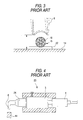
- a conventional ultrasonic welding apparatus 23 comprises an exciter unit composed of a booster 3 and a converter 4 connected to each other; a horn 24 projecting forward from the booster 3; and a welding tip 6 provided to project downward from a forward end of the horn 24.
- the booster 3 is supplied with electric power through the converter 4, and an object to be welded is positioned between the welding tip 6 and an anvil 14, the welding tip 6 is ultrasonically vibrated by ultrasonic vibrational energy generated from the booster 3 so that the object is welded by heat generated by the vibration of the welding tip 6.
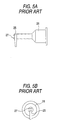
- the horn 24 is detachably attached to the exciter unit so that the welding tip 6 is exchanged together with the horn; or (2) a welding tip 25 is detachably attached to a horn 26 by bolts 27 so that the welding tip 25 is replaced by a new one, as shown in Figs. 5A and 5B.
- an ultrasonic welding apparatus comprising a welding tip projecting downward from a forward end of a horn projecting forward from an exciter unit, wherein the horn is made rotatable around a horizontal axis passing through the center of the horn, and a plurality of welding tips are positioned on the outer circumferential surface of a forward end portion of the horn so that the respective top ends of the welding tips are moved to face a subject to be welded one by one successively as the horn rotates. Ultrasonic vibration is generated by the exciter unit through the horn to thereby weld the subject, which is placed on an anvil and is in contact above with one of the welding tips.
- the respective top ends of the welding tips are moved to face the object on the anvil successively if the horn is rotated.
- the exchange of the welding tips is completed if the rotation of the horn is stopped when a required welding tip faces the subject.
- the respective welding tips also rotate around the horizontal central axis of the horn.
- a required welding tip can be accurately moved to face the subject to be welded if the welding tips are attached around the center axis accurately.
- the horn may be rotated accurately by means of a stepping motor, or the like.
- the transmission of ultrasonic vibrational energy from the exciter unit to the horn is performed evenly and efficiently regardless of the exchange of welding tips because there is no rotational connection portion between the exciter unit and the horn.
- Fig. 1 is a sectional view showing an embodiment of an ultrasonic welding apparatus according to the present invention.
- Fig. 2 is a perspective view showing use of the embodiment of Fig. 1.
- Fig. 3 is a sectional view showing positioning of a welding tip.
- Fig. 4 is a sectional view of a conventional ultrasonic welding apparatus.
- Fig. 5A is a sectional view showing a welding tip which is detachably attached to the horn.
- Fig. 5B is a front view of Fig. 5A.
- An ultrasonic welding apparatus 1 shown in Fig. 1 is used for terminal treatment of an electric cable, and comprises a booster 3 housed in a rectangular-pipe-shaped shell 2 in a state in which a rear end portion projects from the shell 2; a converter 4 connected to the rear end of the booster 3; a horn 5 extending forward from the booster 3 and projecting out from the shell 2; and welding tips 6 positioned at the front end of the horn 5.
- the booster 3 is fixed to the inner wall of the shell 2 through bearings 7 so as to be rotatable.
- the front and rear surfaces of the shell 2 are blocked by diaphragms 9 mounted on retaining rings 8 respectively.
- the converter 4 is connected to an external electric source (not shown) through an electric cable 10 to convert a voltage or current from the external electric source so as to be suitable to the booster 3.
- the converter 4 is housed in a columnar cylinder 11 having its rear end blocked.
- the cylinder 11 is fixed at its front end to the outer circumferential surface of the rear end portion of the booster 3.
- the horn 5 having a shape rotationally symmetrical with respect to a horizontal longitudinal axis is fixed to the booster 3 so that the axis of symmetry coincides with the rotation axis of the booster 3 with respect to the shell 2.
- the horn 5 has a front end portion shaped like a disk with a rotation axis as its center.
- a plurality of welding tips 6 different in shape and size are provided at equal intervals so as to project outward from the disk.
- the welding tips 6 are rotated together with the cylinder 11, the booster 3 and the horn 5 around the above-mentioned rotation axis by means of a motor 13 connected to the rear end of the cylinder 11 through a coupling 12 the welding tips face the upper surface of the anvil 14 successively.
- the motor 13 is a stepping motor which rotates accurately by a predetermined angle to make the horn 5, cylinder 11 and booster 3 rotate so that the top end of a selected welding tip 6 comes into a position to contact a conductor core 16 of an electric cable 15 straightly from above, without any displacement, as indicated by the solid line in Fig. 3.
- the welding apparatus 1 is fixed on a mount 17 supported at its opposite side portions by a support frame 18.
- the support frame 18 is provided at its front lower portion with the anvil 14 projecting forward therefrom so that the mount 17 can be moved up and down by an elevating mechanism (not shown) to moderately press the lower surface of one of the selected welding tips 6 to the electric cable 15 on the anvil 14.
- the electric cable terminal treating work by the ultrasonic welding apparatus 1 is carried out as follows. First, a socket terminal 19 from a hopper is moved on rails 20 extending in the left-to-right direction and is positioned on the anvil 14. Then, an electric cable 15 is carried on a transport table 21 from the front toward the socket terminal 19 on the anvil 14. A coating is peeled from the forward end portion of the electric cable 15 so that the conductor core 16 is exposed. When the carrying is completed, the exposed conductor core 16 is in contact with the upper surface of an electrode plate 22 of the socket terminal 19 as shown in Fig. 3.
- a user operates the stepping motor 12 rotates the cylinder 11, the booster 3, the horn 5, and the welding tips 6, so that a welding tip having a shape and a size corresponding to the size of the electric cable 15 faces the conductor core 16 of the electric cable 15.
- This rotation work can be automated if there is a computer system and various sensors for automatically judging the size of the electric cable 15 in order to make the motor 13 rotate by a required angle.
- the horn 5 is rotated by the motor 13 to replace the welding tip by a required welding tip. Because the welding tip 6 and the horn 5 need not be removed according to the present invention, the replacement of the welding tip 6 by a new one is completed only by rotating the horn 5 by a required angle so that the welding work can be re-started if the positions and angles to mount the welding tips 6 to the horn 5 are adjusted finely in advance.
- the welding tip 6 can be rapidly replaced one by one by successively rotating the motor 13, so that electric wires arranged side by side can be continuously attached to the socket terminal without making the individual electric wires of the flat cable rise one by one.
- a special flat cable can be ultrasonically welded.
- this embodiment shows the case in which the horn 5, the booster 3, the converter 4, and so on, are rotated integrally with each other by means of the motor 13, the invention can be applied to a case in which only the horn 5 is rotated or both the horn 5 and the booster 3 are rotated.
- the horn 5 and the booster 3 are united into one body, the transmission of ultrasonic vibrational energy from the booster 3 to the horn 5 is performed efficiently because there is no rotational connection portion between the horn 5 and the booster 3.
- this embodiment shows the case in which the booster 3 and the horn 5 are moved up and down together with the motor 13, the invention can be applied to a case in which the motor 13 is not moved up and down but the shaft is bent by the coupling 12 so that only the booster 3, and so on, are moved up and down.
- the moving up-and-down method any one of various known methods may be employed.
- the welding tip can be rapidly replaced by a new one different in shape and size, welding work can be re-started rapidly even in the case where the subject to be welded is changed. Furthermore, ultrasonic welding can be performed even in the case where the subject to be welded, such as a special flat cable, must be welded by using a plurality of welding tips different in shape and size. In addition, because the time of use of each welding tip and the number of times each welding tip is used can be accurately and easily determined if the rotational angle, and the like, of the motor is timely monitored and recorded, the welding apparatus can be used in a production line and managed efficiently.
Landscapes
- Engineering & Computer Science (AREA)
- Mechanical Engineering (AREA)
- Manufacturing Of Electrical Connectors (AREA)
- Pressure Welding/Diffusion-Bonding (AREA)
- Wire Processing (AREA)
- Apparatuses For Generation Of Mechanical Vibrations (AREA)
Claims (6)
- Ultraschall-Schweißgerät für die Behandlung des Anschlusses eines elektrischen Kabels mit:gekennzeichnet durcheiner Erregereinheit zum Erzeugen von Ultraschallvibration;einem Arm des Schweißgerätes (horn)(5) mit einem vorderen Ende und welcher um eine horizontale Längsachse drehbar ist;einer Vielzahl von Schweißspitzen (6), die von einer äußeren Umfangsfläche des vorderen Endes des Armes des Schweißgerätes (5) vorstehen, wobei die Schweißspitzen (6) unterschiedliche Gestalten und Größen haben und um die horizontale Achse drehbar sind, undeinem Booster (3) und einem Konverter (4) zum Konvertieren einer Spannung oder eines Stromes von einer elektrischen Quelle in der Erregereinheit,
einen Motor (13), um den Arm des Schweißgerätes um einen vorbestimmten Winkel zu drehen, wobei die Schweißspitzen (6), der Arm des Schweißgerätes (5) und der Booster (3) ein Stück bilden. - Ultraschallschweißgerät nach Anspruch 1, ferner mit einem Anschlußgehäuse, wobei der Booster drehbar an eine Innenwand des Anschlußgehäuses angeschlossen ist.
- Ultraschallschweißgerät nach Anspruch 1, ferner mit:einer Halterung, auf der das Gerät befestigt ist;einem Halterahmen, der an die Halterung angeschlossen ist, und der einen Amboß (14) aufweist, der von einem vorderen Abschnitt des Rahmens vorspringt.
- Ultraschallschweißgerät nach Anspruch 1, ferner mit:einer Einrichtung zur Halterung eines Lagers; undeiner Kupplung, die an den Konverter (4) und den Motor (13) angeschlossen ist.
- Verfahren zum Ultraschallschweißen zur Behandlung der Anschlüsse einer Vielzahl von Elektrokabeln (15) mit unterschiedlichen Gestalten und Größen, wonach:dadurch gekennzeichnet, daßdie vorderen Enden der Elektrokabel (15) zu entsprechenden Sockelanschlüssen verbracht werden;die Umhüllungen der vorderen Enden der Elektrokabel abgeschält werden, um die Leiterkerne freizulegen;Kontaktieren einer ersten Schweißspitze (6) mit einer Größe und einer Gestalt, die einem ersten Elektrokabel entspricht;in Vibration versetzen der ersten Schweißspitze (6), um das erste Elektrokabel an einem entsprechenden Sockelanschluß zu befestigen; undErsetzen der ersten Schweißspitze (6) durch eine zweite Schweißspitze, die eine unterschiedliche Größe und unterschiedliche Gestalt entsprechend einer Größe und Gestalt eines zweiten Elektrokabels aufweist, welches sich von dem ersten Elektrokabel unterscheidet
ein Arm des Schweißgerätes (horn)(5) mit einer Vielzahl von Schweißspitzen, die unterschiedliche Gestalten und unterschiedliche Größen haben, mit Hilfe eines Motors um einen vorbestimmten Winkel gedreht wird, und ein Konverter (4) und ein Booster (3) durch den Motor gedreht werden, wobei die Schweißspitzen (6), der Arm des Schweißgerätes (5) und der Booster (3) ein Teil bilden. - Verfahren zum Ultraschallschweißen nach Anspruch 5, bei dem ferner der Arm des Schweißgerätes (5) und der Booster (3) aufwärts und abwärts bewegt werden, um eine untere Fläche von wenigstens einer der Schweißspitzen (6) auf wenigstens ein Elektrokabel (15) zu pressen.
Applications Claiming Priority (3)
| Application Number | Priority Date | Filing Date | Title |
|---|---|---|---|
| JP27261995 | 1995-10-20 | ||
| JP27261995A JP3455344B2 (ja) | 1995-10-20 | 1995-10-20 | 超音波溶接装置 |
| JP272619/95 | 1995-10-20 |
Publications (3)
| Publication Number | Publication Date |
|---|---|
| EP0769345A1 EP0769345A1 (de) | 1997-04-23 |
| EP0769345B1 true EP0769345B1 (de) | 2001-12-12 |
| EP0769345B2 EP0769345B2 (de) | 2005-01-05 |
Family
ID=17516463
Family Applications (1)
| Application Number | Title | Priority Date | Filing Date |
|---|---|---|---|
| EP96116764A Expired - Lifetime EP0769345B2 (de) | 1995-10-20 | 1996-10-18 | Ultraschallschweissgerät |
Country Status (4)
| Country | Link |
|---|---|
| US (1) | US5947364A (de) |
| EP (1) | EP0769345B2 (de) |
| JP (1) | JP3455344B2 (de) |
| DE (1) | DE69617869T3 (de) |
Families Citing this family (33)
| Publication number | Priority date | Publication date | Assignee | Title |
|---|---|---|---|---|
| US6494976B1 (en) * | 1999-05-18 | 2002-12-17 | Denso Corporation | Ultrasonically joining apparatus and ultrasonically joining method |
| US6474785B1 (en) | 2000-09-05 | 2002-11-05 | Hewlett-Packard Company | Flextensional transducer and method for fabrication of a flextensional transducer |
| ATE328721T1 (de) * | 2001-04-21 | 2006-06-15 | Dynamit Nobel Kunststoff Gmbh | Sonotrode für eine ultraschall-schweissanlage |
| ATE426886T1 (de) * | 2002-08-05 | 2009-04-15 | Holo Point Ltd | Mittel und verfahren zur markierung von produkten |
| KR100513988B1 (ko) * | 2004-09-30 | 2005-09-09 | 주식회사 테크소닉 | 싱글 서포트 방식의 반파장 초음파 진동 시스템 |
| KR100650026B1 (ko) * | 2006-03-15 | 2006-11-28 | 엄기복 | 초음파 접합장치 |
| JP4374040B2 (ja) * | 2007-06-29 | 2009-12-02 | 株式会社東芝 | 半導体製造装置 |
| US8008183B2 (en) * | 2007-10-04 | 2011-08-30 | Texas Instruments Incorporated | Dual capillary IC wirebonding |
| US8215359B2 (en) * | 2009-03-05 | 2012-07-10 | Branson Ultrasonics Corporation | Part sensing horn |
| JP5491081B2 (ja) * | 2009-06-22 | 2014-05-14 | 株式会社アルテクス | 超音波振動金属接合用共振器 |
| KR100939975B1 (ko) * | 2009-07-27 | 2010-02-03 | 서정석 | 초음파 금속 용착 혼 |
| DE102010029395A1 (de) * | 2010-05-07 | 2011-11-10 | Telsonic Holding Ag | Torsionssonotrode, Ultraschall-Schweißvorrichtung und Verfahren zur Herstellung einer Schweißverbindung mittels Ultraschall |
| EP2457683A1 (de) * | 2010-11-25 | 2012-05-30 | Telsonic Holding AG | Torsionales Schweissen |
| US10391579B2 (en) * | 2013-03-15 | 2019-08-27 | Huys Industries Limited | Ventilated vibrating electrode holder |
| US9793571B2 (en) | 2013-10-03 | 2017-10-17 | Nissan Motor Co., Ltd. | Apparatus for bonding separators in electrical devices |
| US10391574B2 (en) | 2013-12-16 | 2019-08-27 | Huys Industries Limited | Welding method and apparatus therefor |
| US9446475B2 (en) * | 2014-04-09 | 2016-09-20 | Fabrisonic, Llc | Weld assembly for ultrasonic additive manufacturing applications |
| DE102014213748A1 (de) | 2014-07-15 | 2016-01-21 | Robert Bosch Gmbh | Ultraschallschweißzange |
| KR102211524B1 (ko) * | 2014-08-11 | 2021-02-02 | 삼성에스디아이 주식회사 | 초음파 용접 장치, 이를 이용한 이차 전지 제조 방법 및 그 이차 전지 |
| US9873534B2 (en) * | 2014-12-19 | 2018-01-23 | Branson Ultrasonics Corporation | Tooling for ultrasonic tube sealer for sealing an end portion of a tube to have a rounded configuration |
| JP6882757B2 (ja) * | 2016-11-22 | 2021-06-02 | 株式会社キーレックス | 超音波接合装置 |
| JP7181217B2 (ja) * | 2017-04-04 | 2022-11-30 | クリック アンド ソッファ インダストリーズ、インク. | 超音波溶接システムおよびその使用方法 |
| CN108247192A (zh) * | 2018-02-06 | 2018-07-06 | 南京航空航天大学 | 一种双联动夹紧金属箔片超声固接装置 |
| US11583950B2 (en) | 2018-06-12 | 2023-02-21 | Huntington Ingalls Incorporated | System and method for ultrasonic additive manufacturing |
| US11224935B2 (en) | 2018-06-12 | 2022-01-18 | Huntington Ingalls Incorporated | System and method for ultrasonic additive manufacturing |
| JP6845188B2 (ja) * | 2018-07-13 | 2021-03-17 | 矢崎総業株式会社 | 端子付き電線及びその製造方法 |
| WO2020105434A1 (ja) * | 2018-11-20 | 2020-05-28 | 株式会社Link-Us | 超音波接合装置 |
| DE102018132839A1 (de) * | 2018-12-19 | 2020-06-25 | Herrmann Ultraschalltechnik Gmbh & Co. Kg | Ultraschallschweißanlage mit Abstützelement |
| US12409504B2 (en) | 2019-02-05 | 2025-09-09 | Huys Industries Limited | Welding applicator and method of application |
| US11697172B2 (en) * | 2019-09-05 | 2023-07-11 | Ohio State Innovation Foundation | Systems and methods for joining and repair using ultrasonic additive manufacturing with a contoured sonotrode |
| WO2021207838A1 (en) | 2020-04-14 | 2021-10-21 | Huys Industries Limited | Welded assembly and method of welding using electro-spark discharge |
| WO2022035924A1 (en) * | 2020-08-12 | 2022-02-17 | Tech-sonic Inc. | Self leveling stack assembly with front-loaded amplitude uniform ultrasonic welding horn |
| US12434324B2 (en) | 2021-11-19 | 2025-10-07 | Lg Energy Solution, Ltd. | Ultrasonic welding device |
Family Cites Families (9)
| Publication number | Priority date | Publication date | Assignee | Title |
|---|---|---|---|---|
| US3780926A (en) * | 1972-06-02 | 1973-12-25 | Dukane Corp | Ultrasonic rigid horn assembly |
| JPS579241A (en) * | 1980-06-17 | 1982-01-18 | Mitsubishi Electric Corp | Connecting method and device for armature coil |
| US4534091A (en) * | 1980-08-20 | 1985-08-13 | General Motors Corporation | Battery grid and method of making same |
| DE3316873A1 (de) * | 1983-05-07 | 1984-11-15 | Schunk Ultraschalltechnik Gmbh, 8750 Aschaffenburg | Vorrichtung zum verbinden elektrischer leiter |
| DE3335254A1 (de) * | 1983-09-29 | 1985-04-18 | Schunk Ultraschalltechnik Gmbh, 8750 Aschaffenburg | Vorrichtung zum verbinden bzw. verdichten elektrischer leiter |
| IT1173463B (it) * | 1984-03-23 | 1987-06-24 | Andrea Spa D | Testa a fresare nonche' a forare per macchina utensile |
| DE3437749A1 (de) * | 1984-10-15 | 1986-04-17 | Schunk Ultraschalltechnik GmbH, 6301 Wettenberg | Verfahren und vorrichtung zum verdichten elektrischer leiter und mechanischen und elektrisch leitenden verbinden dieser auf einem traeger |
| US4867370A (en) * | 1987-04-09 | 1989-09-19 | American Technology, Inc. | Apparatus and method for ultrasonic welding of wires |
| US4852788A (en) * | 1988-06-16 | 1989-08-01 | American Technology, Inc. | Method and apparatus of ultrasonic gang welding |
-
1995
- 1995-10-20 JP JP27261995A patent/JP3455344B2/ja not_active Expired - Fee Related
-
1996
- 1996-10-16 US US08/732,993 patent/US5947364A/en not_active Expired - Fee Related
- 1996-10-18 DE DE69617869T patent/DE69617869T3/de not_active Expired - Fee Related
- 1996-10-18 EP EP96116764A patent/EP0769345B2/de not_active Expired - Lifetime
Also Published As
| Publication number | Publication date |
|---|---|
| DE69617869D1 (de) | 2002-01-24 |
| EP0769345B2 (de) | 2005-01-05 |
| EP0769345A1 (de) | 1997-04-23 |
| JPH09108855A (ja) | 1997-04-28 |
| DE69617869T3 (de) | 2005-05-19 |
| DE69617869T2 (de) | 2002-04-25 |
| US5947364A (en) | 1999-09-07 |
| JP3455344B2 (ja) | 2003-10-14 |
Similar Documents
| Publication | Publication Date | Title |
|---|---|---|
| EP0769345B1 (de) | Ultraschallschweissgerät | |
| EP0062996B1 (de) | Kassettenumlaufschweisskopf | |
| JP5076125B2 (ja) | 超音波溶着機、超音波溶着システム | |
| CN115365720B (zh) | 一种具有导电滑环的焊接设备 | |
| JPH09199196A (ja) | フラットケーブルと端子の接続構造 | |
| JP3541534B2 (ja) | 回転電機の回転子の製造方法 | |
| JP2008136270A (ja) | 給電装置 | |
| WO1988008352A1 (fr) | Machine de soudage a l'arc tournant a haute vitesse | |
| CA1049623A (en) | Apparatus for welding a tube to a tube sheet | |
| JP3338008B2 (ja) | 超音波振動用共振器の支持装置 | |
| EP0234750B1 (de) | Stromabnehmende Anordnung für einen drehbaren Körper | |
| JP2553126Y2 (ja) | 放電加工機 | |
| JP3249322U (ja) | ターンテーブル型電極ホルダ | |
| CN113182676B (zh) | 一种焊接组件及电池转接片的焊接方法 | |
| JP3376695B2 (ja) | 高周波加熱装置 | |
| JP2559887Y2 (ja) | 電極装置 | |
| JP2010541524A (ja) | 電気機器用のカーボンブラシ装置 | |
| JPS6217467B2 (de) | ||
| KR950005478Y1 (ko) | 저항용접기의 원판전극전원 공급장치 | |
| JPH06198455A (ja) | 抵抗溶接方法 | |
| JPS61147751A (ja) | アマチユアの絶縁処理方法 | |
| JPH09283250A (ja) | 外部回転電源接続装置 | |
| JPH0421675Y2 (de) | ||
| JPS6024546B2 (ja) | 通電加熱装置 | |
| JPS5918828Y2 (ja) | 高圧ケ−ブルの受口 |
Legal Events
| Date | Code | Title | Description |
|---|---|---|---|
| PUAI | Public reference made under article 153(3) epc to a published international application that has entered the european phase |
Free format text: ORIGINAL CODE: 0009012 |
|
| AK | Designated contracting states |
Kind code of ref document: A1 Designated state(s): DE FR GB |
|
| 17P | Request for examination filed |
Effective date: 19970829 |
|
| 17Q | First examination report despatched |
Effective date: 19981016 |
|
| GRAG | Despatch of communication of intention to grant |
Free format text: ORIGINAL CODE: EPIDOS AGRA |
|
| GRAG | Despatch of communication of intention to grant |
Free format text: ORIGINAL CODE: EPIDOS AGRA |
|
| GRAH | Despatch of communication of intention to grant a patent |
Free format text: ORIGINAL CODE: EPIDOS IGRA |
|
| GRAH | Despatch of communication of intention to grant a patent |
Free format text: ORIGINAL CODE: EPIDOS IGRA |
|
| GRAA | (expected) grant |
Free format text: ORIGINAL CODE: 0009210 |
|
| AK | Designated contracting states |
Kind code of ref document: B1 Designated state(s): DE FR GB |
|
| REG | Reference to a national code |
Ref country code: GB Ref legal event code: IF02 |
|
| REF | Corresponds to: |
Ref document number: 69617869 Country of ref document: DE Date of ref document: 20020124 |
|
| ET | Fr: translation filed | ||
| PLBQ | Unpublished change to opponent data |
Free format text: ORIGINAL CODE: EPIDOS OPPO |
|
| PLBI | Opposition filed |
Free format text: ORIGINAL CODE: 0009260 |
|
| PLBF | Reply of patent proprietor to notice(s) of opposition |
Free format text: ORIGINAL CODE: EPIDOS OBSO |
|
| 26 | Opposition filed |
Opponent name: SCHUNK ULTRASCHALLTECHNIK GMBH Effective date: 20020912 |
|
| PLBF | Reply of patent proprietor to notice(s) of opposition |
Free format text: ORIGINAL CODE: EPIDOS OBSO |
|
| RAP2 | Party data changed (patent owner data changed or rights of a patent transferred) |
Owner name: SUMITOMO ELECTRIC INDUSTRIES, LTD. Owner name: SUMITOMO WIRING SYSTEMS, LTD. Owner name: AUTONETWORKS TECHNOLOGIES, LTD. |
|
| PLAY | Examination report in opposition despatched + time limit |
Free format text: ORIGINAL CODE: EPIDOSNORE2 |
|
| PLBC | Reply to examination report in opposition received |
Free format text: ORIGINAL CODE: EPIDOSNORE3 |
|
| PUAH | Patent maintained in amended form |
Free format text: ORIGINAL CODE: 0009272 |
|
| STAA | Information on the status of an ep patent application or granted ep patent |
Free format text: STATUS: PATENT MAINTAINED AS AMENDED |
|
| 27A | Patent maintained in amended form |
Effective date: 20050105 |
|
| AK | Designated contracting states |
Kind code of ref document: B2 Designated state(s): DE FR GB |
|
| PGFP | Annual fee paid to national office [announced via postgrant information from national office to epo] |
Ref country code: FR Payment date: 20051010 Year of fee payment: 10 |
|
| PGFP | Annual fee paid to national office [announced via postgrant information from national office to epo] |
Ref country code: GB Payment date: 20051012 Year of fee payment: 10 |
|
| PGFP | Annual fee paid to national office [announced via postgrant information from national office to epo] |
Ref country code: DE Payment date: 20051014 Year of fee payment: 10 |
|
| ET3 | Fr: translation filed ** decision concerning opposition | ||
| PG25 | Lapsed in a contracting state [announced via postgrant information from national office to epo] |
Ref country code: DE Free format text: LAPSE BECAUSE OF NON-PAYMENT OF DUE FEES Effective date: 20070501 |
|
| GBPC | Gb: european patent ceased through non-payment of renewal fee |
Effective date: 20061018 |
|
| REG | Reference to a national code |
Ref country code: FR Ref legal event code: ST Effective date: 20070629 |
|
| PG25 | Lapsed in a contracting state [announced via postgrant information from national office to epo] |
Ref country code: GB Free format text: LAPSE BECAUSE OF NON-PAYMENT OF DUE FEES Effective date: 20061018 |
|
| PG25 | Lapsed in a contracting state [announced via postgrant information from national office to epo] |
Ref country code: FR Free format text: LAPSE BECAUSE OF NON-PAYMENT OF DUE FEES Effective date: 20061031 |
|
| PLAB | Opposition data, opponent's data or that of the opponent's representative modified |
Free format text: ORIGINAL CODE: 0009299OPPO |