EP0769603A2 - Ferrure pour fenêtre et fenêtre oscillo-battante avec une telle ferrure - Google Patents
Ferrure pour fenêtre et fenêtre oscillo-battante avec une telle ferrure Download PDFInfo
- Publication number
- EP0769603A2 EP0769603A2 EP96116375A EP96116375A EP0769603A2 EP 0769603 A2 EP0769603 A2 EP 0769603A2 EP 96116375 A EP96116375 A EP 96116375A EP 96116375 A EP96116375 A EP 96116375A EP 0769603 A2 EP0769603 A2 EP 0769603A2
- Authority
- EP
- European Patent Office
- Prior art keywords
- bearing
- frame
- fitting
- axis
- section
- Prior art date
- Legal status (The legal status is an assumption and is not a legal conclusion. Google has not performed a legal analysis and makes no representation as to the accuracy of the status listed.)
- Withdrawn
Links
Images


Classifications
-
- E—FIXED CONSTRUCTIONS
- E05—LOCKS; KEYS; WINDOW OR DOOR FITTINGS; SAFES
- E05D—HINGES OR SUSPENSION DEVICES FOR DOORS, WINDOWS OR WINGS
- E05D15/00—Suspension arrangements for wings
- E05D15/48—Suspension arrangements for wings allowing alternative movements
- E05D15/52—Suspension arrangements for wings allowing alternative movements for opening about a vertical as well as a horizontal axis
- E05D15/5202—Suspension arrangements for wings allowing alternative movements for opening about a vertical as well as a horizontal axis with non-horizontally extending checks
-
- E—FIXED CONSTRUCTIONS
- E05—LOCKS; KEYS; WINDOW OR DOOR FITTINGS; SAFES
- E05D—HINGES OR SUSPENSION DEVICES FOR DOORS, WINDOWS OR WINGS
- E05D15/00—Suspension arrangements for wings
- E05D15/48—Suspension arrangements for wings allowing alternative movements
- E05D15/52—Suspension arrangements for wings allowing alternative movements for opening about a vertical as well as a horizontal axis
- E05D15/522—Suspension arrangements for wings allowing alternative movements for opening about a vertical as well as a horizontal axis with disconnecting means for the appropriate pivoting parts
- E05D15/523—Suspension arrangements for wings allowing alternative movements for opening about a vertical as well as a horizontal axis with disconnecting means for the appropriate pivoting parts using movable rods
-
- E—FIXED CONSTRUCTIONS
- E05—LOCKS; KEYS; WINDOW OR DOOR FITTINGS; SAFES
- E05D—HINGES OR SUSPENSION DEVICES FOR DOORS, WINDOWS OR WINGS
- E05D15/00—Suspension arrangements for wings
- E05D15/48—Suspension arrangements for wings allowing alternative movements
- E05D15/52—Suspension arrangements for wings allowing alternative movements for opening about a vertical as well as a horizontal axis
- E05D15/526—Safety devices
-
- E—FIXED CONSTRUCTIONS
- E05—LOCKS; KEYS; WINDOW OR DOOR FITTINGS; SAFES
- E05Y—INDEXING SCHEME ASSOCIATED WITH SUBCLASSES E05D AND E05F, RELATING TO CONSTRUCTION ELEMENTS, ELECTRIC CONTROL, POWER SUPPLY, POWER SIGNAL OR TRANSMISSION, USER INTERFACES, MOUNTING OR COUPLING, DETAILS, ACCESSORIES, AUXILIARY OPERATIONS NOT OTHERWISE PROVIDED FOR, APPLICATION THEREOF
- E05Y2900/00—Application of doors, windows, wings or fittings thereof
- E05Y2900/10—Application of doors, windows, wings or fittings thereof for buildings or parts thereof
- E05Y2900/13—Type of wing
- E05Y2900/148—Windows
Definitions
- the invention relates to a fitting according to the preamble of claim 1 or 9 and to a window according to the preamble of claim 10.
- Tilt and turn windows and fittings used for this are known in various designs.
- the turn-and-tilt fittings used for these windows are based on the basic principle that a handlebar arrangement connecting the stick frame and sash frame is provided, which limits the tilting movement when the sash frame is tilted, and that a swivel joint is also provided which prevents rotation or Swiveling the casement around the desired swivel axis, ie usually allows vertical axis.
- a control and locking device can be used to switch between the turning function and the tilting function, for example by locking the handlebar for the turning function on the casement or on a bearing element provided there.
- the object of the invention is to show a fitting which is characterized by a particularly simple and effective construction.
- a fitting for rotating and tilting windows is designed according to the characterizing part of claim 1 or.
- a tilt and turn window is designed in accordance with the characterizing part of patent claim 10.
- the invention relates to a turn-tilt fitting for corresponding turn and tilt windows.
- the peculiarity of this fitting is that in the case of the fitting on the pivoting or rotating side of the casement frame and of the stick frame for fitting fitting, the handlebars also form the pivot pin of the pivot joint for the pivoting or pivoting function.
- the invention is characterized by a particularly simple and compact construction.
- the handlebar is preferably a bolt.
- the invention relates to a fitting designed as an auxiliary bearing or roller casserole, with which, at least when the window sash is closed and / or the window sash is tilted, support is provided for this sash or the sash frame below, specifically on the side facing away from the pivoting side.
- This auxiliary bearing consists of a first bearing element which is provided on the underside of the casement and is connected to a push rod of the window gear mechanism there, in such a way that this bearing element can be moved from a first position into at least a second position.
- the first bearing element On the underside facing the stick frame, the first bearing element has at least one wedge surface and an adjoining support surface.
- a second bearing element is provided with a counter surface cooperating with the wedge surface and the support surface, in such a way that when the bearing element is moved from the first position to the second position, the first bearing element first with its wedge surface and then with its contact surface against the counter surface of the second bearing element comes to rest and thereby lifting and subsequently supporting the casement is achieved.
- This auxiliary bearing is particularly suitable for use together with the turn-tilt fitting, which is provided on the swivel or hinge side of the window.
- This fitting which is designed as an auxiliary bearing, is generally suitable for windows, in particular tilt-and-turn windows.
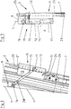
- 1 is the floor frame and 2 is the sash frame of an exterior window, which is designed as a rotating and tilting window.
- Figure 1 shows the arched window in the upper area from the inside of the building.
- the sash 2 is provided with the glazing in the usual way.
- the frame 1 and the sash 2 are each metal profile frame.
- the stick frame 1 and / or the sash frame 2 can, however, also be made of another material suitable for windows, for example of wood.
- the usual hand lever 3 is provided, which is part of a transmission via which, inter alia, the locks 4 which lock the casement 2 in the frame 1 when the window is closed, and in particular also a turn-tilt fitting 5 are actuated, so that it has at least two functions, namely a function in which this fitting acts as a hinge, which enables pivoting or turning of the wing 2 about the vertical axis V, and a second function, in which the fitting 5 acts as a tilt fitting, which limits the tilting of the window or the sash 2 about the horizontal axis H to a maximum value.
- the turn-tilt fitting 5 is located on the other vertical section 2 ′′ of the sash frame 2, which does not have the hand lever 3 and forms the pivoting side, in the embodiment shown where this vertical section 2 ′′ in the upper , arcuate section 2 '''.
- the horizontal tilt axis H is in the usual way below the lower horizontal section 2 '''' of the casement 2. Where the section 2 '' merges into the section 2 '''', the window between the floor frame and the Sash frame 2 a conventional turn-tilt bearing 6, which allows pivoting and tilting.
- the gear cooperating with the hand lever 3 consists essentially of push and pull rods 7, which are provided on the sections 2 ', 2' 'and 2' ''' 'and partly on the arcuate section 2' '' and are driven by corner drives 8 with each other are connected.
- the locks 4 are usually provided on the push rods 7 on the section 2 'not having the fitting 5 and the bearing 6, and in some cases also on the section 2' ''.
- the push and pull rods 7 are guided in guides in the area of the fold of the casement 2, specifically in the casement 2 consisting of metal profiles in corresponding guide grooves prepared in these profiles.
- the hand lever 3 has a total of three functional positions, namely a position Z, which corresponds to the closed and locked sash frame 2, a position D, which allows the sash frame 2 to be rotated or pivoted about the vertical axis V, and the position K, which is a Tilting the casement around the horizontal axis H allows.
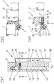
- the turn-tilt fitting 5 according to the invention is shown in more detail in FIGS. 2-11.
- This fitting consists in the embodiment shown, among others. from a bearing 9, which can be fastened to the stick frame 1 or the inner surface 1 'there in such a way that this bearing protrudes on the inside of the window over the there surface 1' of the stick frame.
- the bearing 9 has an angled portion 10 with which the bearing 9 can be fastened to a T-groove on the profile of the frame 1 in the region of the window rebate.
- the fitting 5 also consists of a bearing 11 which can be attached to the casement 2, in such a way that this bearing 11 is also on the inside of the Window is located and on the side of the casement 2 facing away from the casement opening or the glazing protrudes with a partial area 12 which, in the embodiment shown, is approximately sleeve-shaped or cylindrical with an axis L parallel to the axis V and with the window casement or casement closed 2 seen from the inside of the window in front of the inner surface 1 'of the frame 1 below the bearing 9 and is provided next to this.
- the bearing 11 also has a section 13 with which the bearing 11 is fastened to the sash frame 2, in the embodiment shown on the side of the sash frame 2 having the fold.
- the section 13 is used for this purpose as a holding block molded web executed, the latter merges into section 12.
- a bearing bore 14 is provided, which lies with its axis parallel to the longitudinal axis L of the section 12 and is open at the top and bottom of this section.
- the bore 14 has two sections, namely the lower section 14 'with a larger cross section and the upper bore section 14' 'with a reduced cross section compared to the section 14'.
- the bore sections 14 ′ and 14 ′′ are slit over the entire length in the embodiment shown, namely on the back of the section 12, which is adjacent to the inside 1 'of the frame 1 when the casement 2 is closed, or faces the inside 1' of the frame 1 when the casement 2 is tilted.
- a pin 15 is pivotally mounted by means of a hinge pin 16, namely about an axis parallel to the tilt axis or axis H, ie about a horizontal axis parallel to the plane of the window.
- the bolt 15, which has an outer diameter that is the same or slightly smaller than the cross section of the bore section 14 ′′, has at its lower end a head 17 with an enlarged cross section, ie with an outer cross section that is equal to or is slightly smaller than the cross section of the bore section 14 ', but in any case is larger than the cross section of the bore section 14''.
- the head 17 of the bolt 15 is arranged in the bore section 14 'in such a way that when the casement 2 is closed, the head 17 is adjacent to the lower, open end of the bore section 14' and a distance from the transition 14 '' 'between the bore portion 14' and 14 ''.
- the pin 15 can also move laterally into and out of the bore section 14 ′′ by pivoting around the head 17 and around the hinge pin.
- the head 17 is rounded at least on its side facing the hinge pin 16; in the embodiment shown, the head 17 is designed as a ball as a whole, in one piece with the remaining pin 15.
- this locking device 19 is also provided, with which the slot 18 can be closed, controlled by the hand lever 3, for a lateral exit of the bolt 15 from the bore section 14.
- this locking device 19 consists essentially of a locking pin 20, which is provided in the bearing 11 in the region of the upper, open end of the bore section 14 in an axially displaceable manner, namely in an axial direction perpendicular to the axis L of the bore 14 and in the illustrated Embodiment in an axial direction parallel to the tilt axis H.
- the locking pin 20 is in this case axially displaceable between a position in which it extends with a partial area into the slot 18 and thereby closes it ⁇ and a position in which the locking pin 20 is completely outside the slot 18 is located.
- the locking pin 20 is prestressed into the non-locking position by a spring 21.
- the spring 21, which is designed as a compression spring, is arranged within a bore 22 of the bearing 11 that also receives the locking pin 20, specifically the locking pin 20 enclosing such that the spring 21 is supported at one end on a head 23 of the locking pin 20 facing away from the slot 18 and at its other end on a surface of the bore 20.
- the spherically rounded head 23 on its side facing away from the locking pin 20 interacts with a control surface or longitudinal side of a control slide 25 which has a control groove 24 and which is connected via a coupling piece 26 to the push rod 7 at section 2 ′′.
- the control slide 25 is also guided parallel to the longitudinal axis L of the section 2 '' on this section in the region of the fold of the sash 2 in the longitudinal direction, and also in a guide opening 27 formed in the bearing 11 or in the partial section 13 there, which the Cross section of the control slide 25 formed by a flat material has a rectangular cross section.
- the wedge-like control groove 24 which interacts with the locking pin 20 is also located in the region of this guide opening 27.
- the coupling piece 26 is designed so that it produces a pull and push connection in the longitudinal direction of the control slide 25 with the respective push rod 7, but to compensate for tolerances, a relative pivoting of the push rod 7 and the control slide 25 about the axis perpendicular to the push and pull movement enables.
- the bolt 15 has an annular groove-like cut 28 which surrounds the bolt axis and on which the bolt 15 has a somewhat reduced outer cross section.
- the arrangement is also such that when the bolt 15 is fully moved into the bore 14, the locking pin 20 can only reach its locking position when the incision 28 is in the area of the locking pin 20, ie the axis distance that the axis of the Locking pin 20 from the axis of the bore 14 is slightly smaller than the sum of half the diameter of the bolt 15 and the locking pin 20, namely by the amount smaller, which corresponds to the depth of the incision 28.
- the functional elements of the turn-tilt fitting 5 assume the positions shown in FIGS. the bolt 15 is completely moved into the bore 14 and in particular also into the section 14 ′′ and by the control slide 25 the locking pin 20 is locked in its locking position in which it closes the slot 18 and the bolt 15 in the region of the incision 28 engages behind on its side facing the slot 18.
- the head 17 is located at a distance X below the transition 14 '' '.
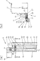
- FIGS. 7 and 8 show the state when the window sash 2 is opened by turning.
- the hand lever 3 is in the position D.
- the locking pin 20 or its head 23 lies against the longitudinal side of the control lever 25 serving as a control surface outside of the control groove 24 and is thereby held in its locking position, however, the locks are unlocked so that the sash 2 can now be pivoted about the axis V around the bolt 15 of the fitting 5, which now acts as a hinge pin, and the turn-tilt bearing 6, the bearing thereby 11 pivots on the non-rotating bolt 15.
- the locking pin 20 keeps the latter permanently locked in the bore section 14 ′′.
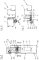
- Figures 9-11 show the state with the wing frame 2 partially tilted.
- the hand lever 3 is in position K.
- the control slide 25 is shifted so far that the head 23 of the locking pin 20 engages in the control groove, causing the locking pin 20 over the spring 21 releases the slot 18, so the bolt 15 can pivot laterally out of the bore 14 so that it is only held with the head 17 on the bearing 11, whereby the sash 2 is tilted about the axis H.
- the maximum tilting position is specified via the bolts 15 connecting the bearings 9 and 11, in which the head 17 then bears against the transition 14 '''.
- the sash frame 2 is tilted back into the stick frame 1 in the usual manner, whereupon the control slide 25 can be moved back into the position shown in FIG. 4 or FIG. 7, in the locking pin 20 in the locked position, via the hand lever 3 is held.
- FIGS. 12 and 13 show an auxiliary bearing arrangement or a roller caster 29 which is provided for additional support between the frame 1 and the sash 2 on the underside of the sash 2 or on the section 2 '''' there, specifically on the Transition between the sections 2 'and 2'''', ie on the side of the lower section 2''''which does not have the pivot and tilt bearing 6.
- the auxiliary bearing 29 consists essentially of a bearing element 30 which is provided on the push rod 7 at the lower section 2 '''' and has a V-shaped groove or recess 31 on its underside, the lateral boundaries of which form two wedge surfaces 32 which form cut at the bottom of the recess 31, the line of intersection of this wedge surface 32 running perpendicular to the plane of the casement 2 and thus in any case also perpendicular to the movement of the push rod 7.
- the auxiliary bearing 29 also consists of a bearing element 33 which is opposite the bearing element 30 on the stick frame 1 is provided, just like the bearing element 30 in the region of the fold.
- a roller or roller 34 is freely rotatably mounted, namely about the axis perpendicular to the plane of the frame and thus also perpendicular to the plane of the closed casement 2.
- the two bearing elements 30 and 33 are further mounted so that in the position of Push rod 7, which corresponds to the middle position D of the hand lever 3, the roller 34 is in the region of the recess 31, that is, the roller 34 is spaced from the bearing element 30, and that in the two positions Z and K of the handle 3 there is Bearing element 30 is supported on the roller 34 with one of the contact surfaces 30 ', which are formed on both sides of the recess 31 on the underside of the bearing element 30.
- the bearing element 30 When the hand lever 3 is moved from the position D to the position Z or K, the bearing element 30 thus moves with one of the wedge surfaces 32 on the roller 34 and is then in contact with the roller 34 with one of the surfaces 30 ', so that here a first certain lifting of the sash 2 on the turn-tilt bearing 6 facing away, which prevents sagging of the casement, especially when tilting.
- the use of the auxiliary bearing 29 is particularly expedient because the turn-tilt fitting 5 acts on a vertical side, namely on the section 2 ′′ of the sash frame 2 and limits the tilting movement and not in the middle of the upper sash frame section 2 ′′ ′′, which would not be possible with the arcuate design of this section.
- the lock 19 in such a way that it enables the bolt 15 or another element that takes over the function of this bolt to be resiliently engaged in the corresponding bearing 11 when the sash frame is closed, ie the lock is locked by spring means in its Biased position, and then this locking position is released by operating the hand lever 3 or the associated gear.
Landscapes
- Engineering & Computer Science (AREA)
- Mechanical Engineering (AREA)
- Wing Frames And Configurations (AREA)
- Hinges (AREA)
Applications Claiming Priority (2)
| Application Number | Priority Date | Filing Date | Title |
|---|---|---|---|
| DE1995138817 DE19538817C2 (de) | 1995-10-18 | 1995-10-18 | Beschlag für Fenster sowie Dreh-Kipp-Fenster mit einem solchen Beschlag |
| DE19538817 | 1995-10-18 |
Publications (2)
| Publication Number | Publication Date |
|---|---|
| EP0769603A2 true EP0769603A2 (fr) | 1997-04-23 |
| EP0769603A3 EP0769603A3 (fr) | 1997-09-24 |
Family
ID=7775184
Family Applications (1)
| Application Number | Title | Priority Date | Filing Date |
|---|---|---|---|
| EP96116375A Withdrawn EP0769603A3 (fr) | 1995-10-18 | 1996-10-12 | Ferrure pour fenêtre et fenêtre oscillo-battante avec une telle ferrure |
Country Status (2)
| Country | Link |
|---|---|
| EP (1) | EP0769603A3 (fr) |
| DE (1) | DE19538817C2 (fr) |
Cited By (1)
| Publication number | Priority date | Publication date | Assignee | Title |
|---|---|---|---|---|
| EP0980952A3 (fr) * | 1998-08-19 | 2001-06-27 | Benedetto Caruso | Châssis de porte ou de fenêtre à battant articulé latéral ou en bas |
Families Citing this family (1)
| Publication number | Priority date | Publication date | Assignee | Title |
|---|---|---|---|---|
| DE20213559U1 (de) * | 2002-09-03 | 2004-01-15 | Mayer & Co. | Beschlagsystem mit Sicherheitselement |
Family Cites Families (5)
| Publication number | Priority date | Publication date | Assignee | Title |
|---|---|---|---|---|
| DE1110547B (de) * | 1957-05-02 | 1961-07-06 | Jaeger Frank & Co Kom Ges | Ausstellvorrichtung fuer wahlweise um eine lotrechte Achse schwenkbare und um eine waagerechte Achse kippbare Fluegel von Fenstern, Tueren od. dgl. |
| AT276655B (de) * | 1967-12-15 | 1969-11-25 | Wiener Schwachstromwerke Gmbh | Gekühlte Stranggießkokille, insbesondere für den Bandguß |
| DE1813011A1 (de) * | 1968-12-06 | 1970-07-09 | Basf Ag | Photopolymerisierbare Stoffmischungen |
| DE2206764A1 (de) * | 1972-02-12 | 1973-08-16 | Heinr Strenger Fa | Kipplager fuer schwenk- und kippbare fluegelrahmen von fenstern oder tueren |
| DE8201880U1 (de) * | 1982-01-27 | 1982-06-16 | Siegenia-Frank Kg, 5900 Siegen | Drehkippfenster, drehkipptuer od.dgl. mit einem seitenscharnier und einem ausstellarm |
-
1995
- 1995-10-18 DE DE1995138817 patent/DE19538817C2/de not_active Expired - Fee Related
-
1996
- 1996-10-12 EP EP96116375A patent/EP0769603A3/fr not_active Withdrawn
Cited By (1)
| Publication number | Priority date | Publication date | Assignee | Title |
|---|---|---|---|---|
| EP0980952A3 (fr) * | 1998-08-19 | 2001-06-27 | Benedetto Caruso | Châssis de porte ou de fenêtre à battant articulé latéral ou en bas |
Also Published As
| Publication number | Publication date |
|---|---|
| EP0769603A3 (fr) | 1997-09-24 |
| DE19538817A1 (de) | 1997-05-22 |
| DE19538817C2 (de) | 1998-09-10 |
Similar Documents
| Publication | Publication Date | Title |
|---|---|---|
| DE2920581C2 (de) | Zusatzverriegelung, insbesondere Mittelverriegelung, für Fenster, Türen od.dgl. | |
| DE68903724T2 (de) | Beschlag fuer tuer, fenster oder dergleichen. | |
| EP0578004B1 (fr) | Crémone-serrure avec pêne pivotant manoeuvré par une broche qui suit une coulisse | |
| EP1312743B1 (fr) | Dispositif de blocage pour un vantail coulissant et levant; ferrure du type crémone avec un tel dispositif; porte ou fenêtre coulissante et levante avec un tel dispositif | |
| DE19511929C1 (de) | Dreh- und/oder Kipp-Beschlag für Fenster, Türen od. dgl. mit einem zwischen dem Flügel und dem Rahmen angeordneten Flügelheber | |
| DE19521539B4 (de) | Drehlager, insbesondere Scherenlager eines Drehbeschlags oder Dreh-Kippbeschlags für Fenster, Türen oder dergleichen | |
| DE202021102238U1 (de) | Drehkippfenster und Beschlaganordnung | |
| DE3033751C2 (de) | Beschlag für den Schiebeflügel von Fenstern, Türen oder dgl. aus Holz- oder Kunststoffprofilen | |
| EP3985216A1 (fr) | Système de battant | |
| EP0021080B1 (fr) | Fenêtre ou porte levante, coulissante ou basculante | |
| WO2015003872A1 (fr) | Ferrure pour une fenêtre, une porte ou analogue comportant un vantail basculant ou coulissant | |
| EP0096744A2 (fr) | Ferrure pour battant oscillo-battant | |
| DE19538817C2 (de) | Beschlag für Fenster sowie Dreh-Kipp-Fenster mit einem solchen Beschlag | |
| EP4105416B1 (fr) | Dispositif de blocage pour une porte bâtie de deux côtés | |
| DE1958413C3 (de) | Ausstellvorrichtung für Kippflügel | |
| DE2658626B2 (de) | Schaltsperre für Treibstangenbeschläge | |
| EP1522666B1 (fr) | Ferrure pour portes ou fenêtres à soulèvement et coulissement et chariot pour un tel ferrure. | |
| DE60101813T2 (de) | Ecklager für Türen, Fenster oder dergleichen | |
| DE4424050A1 (de) | Gelenkkonstruktion für einen schwenkbaren Flügel eines Fahrzeugfensters | |
| DE29907975U1 (de) | Laufschuh für einen Parallelschiebe- und Kippbeschlag eines Gebäudefensters oder einer Gebäudefenstertür sowie Gebäudefenster bzw. Gebäudefenstertür mit einem solchen Parallelschiebe-Kippbeschlag | |
| DE19909365A1 (de) | Vorrichtung zum Feststellen und Verriegeln von Türen oder Wandelementen | |
| DE9218194U1 (de) | Treibstangenverschluß mit schlitz/zapfengesteuertem Riegel | |
| EP1391575B1 (fr) | Dispositif d'actionnement pour l'utilisation dans une ferrure pour une porte à soulèvement et coulissement ou une fenêtre à soulèvement et coulissement | |
| EP4174264A1 (fr) | Agencement de battant | |
| EP1612353B1 (fr) | Ensemble pivot pour un vantail moyen pivotable d'une fenêtre ou d'une porte à au moins trois vantails |
Legal Events
| Date | Code | Title | Description |
|---|---|---|---|
| PUAI | Public reference made under article 153(3) epc to a published international application that has entered the european phase |
Free format text: ORIGINAL CODE: 0009012 |
|
| AK | Designated contracting states |
Kind code of ref document: A2 Designated state(s): AT CH DE IT LI |
|
| PUAL | Search report despatched |
Free format text: ORIGINAL CODE: 0009013 |
|
| AK | Designated contracting states |
Kind code of ref document: A3 Designated state(s): AT BE CH DE DK ES FI FR GB GR IE IT LI LU MC NL PT SE |
|
| RBV | Designated contracting states (corrected) |
Designated state(s): AT CH DE IT LI |
|
| 17P | Request for examination filed |
Effective date: 19971104 |
|
| 17Q | First examination report despatched |
Effective date: 19980513 |
|
| GRAG | Despatch of communication of intention to grant |
Free format text: ORIGINAL CODE: EPIDOS AGRA |
|
| GRAG | Despatch of communication of intention to grant |
Free format text: ORIGINAL CODE: EPIDOS AGRA |
|
| GRAH | Despatch of communication of intention to grant a patent |
Free format text: ORIGINAL CODE: EPIDOS IGRA |
|
| STAA | Information on the status of an ep patent application or granted ep patent |
Free format text: STATUS: THE APPLICATION IS DEEMED TO BE WITHDRAWN |
|
| 18D | Application deemed to be withdrawn |
Effective date: 19990907 |