EP0769623B1 - Spiralanlage zur Fluidverdrängung mit Scheibe zur axialen Dichtung - Google Patents
Spiralanlage zur Fluidverdrängung mit Scheibe zur axialen Dichtung Download PDFInfo
- Publication number
- EP0769623B1 EP0769623B1 EP96116576A EP96116576A EP0769623B1 EP 0769623 B1 EP0769623 B1 EP 0769623B1 EP 96116576 A EP96116576 A EP 96116576A EP 96116576 A EP96116576 A EP 96116576A EP 0769623 B1 EP0769623 B1 EP 0769623B1
- Authority
- EP
- European Patent Office
- Prior art keywords
- involute
- edge
- spiral element
- scroll type
- slit
- Prior art date
- Legal status (The legal status is an assumption and is not a legal conclusion. Google has not performed a legal analysis and makes no representation as to the accuracy of the status listed.)
- Expired - Lifetime
Links
Images




Classifications
-
- F—MECHANICAL ENGINEERING; LIGHTING; HEATING; WEAPONS; BLASTING
- F04—POSITIVE - DISPLACEMENT MACHINES FOR LIQUIDS; PUMPS FOR LIQUIDS OR ELASTIC FLUIDS
- F04C—ROTARY-PISTON, OR OSCILLATING-PISTON, POSITIVE-DISPLACEMENT MACHINES FOR LIQUIDS; ROTARY-PISTON, OR OSCILLATING-PISTON, POSITIVE-DISPLACEMENT PUMPS
- F04C2/00—Rotary-piston machines or pumps
- F04C2/02—Rotary-piston machines or pumps of arcuate-engagement type, i.e. with circular translatory movement of co-operating members, each member having the same number of teeth or tooth-equivalents
-
- F—MECHANICAL ENGINEERING; LIGHTING; HEATING; WEAPONS; BLASTING
- F04—POSITIVE - DISPLACEMENT MACHINES FOR LIQUIDS; PUMPS FOR LIQUIDS OR ELASTIC FLUIDS
- F04C—ROTARY-PISTON, OR OSCILLATING-PISTON, POSITIVE-DISPLACEMENT MACHINES FOR LIQUIDS; ROTARY-PISTON, OR OSCILLATING-PISTON, POSITIVE-DISPLACEMENT PUMPS
- F04C27/00—Sealing arrangements in rotary-piston pumps specially adapted for elastic fluids
- F04C27/005—Axial sealings for working fluid
-
- F—MECHANICAL ENGINEERING; LIGHTING; HEATING; WEAPONS; BLASTING
- F04—POSITIVE - DISPLACEMENT MACHINES FOR LIQUIDS; PUMPS FOR LIQUIDS OR ELASTIC FLUIDS
- F04C—ROTARY-PISTON, OR OSCILLATING-PISTON, POSITIVE-DISPLACEMENT MACHINES FOR LIQUIDS; ROTARY-PISTON, OR OSCILLATING-PISTON, POSITIVE-DISPLACEMENT PUMPS
- F04C18/00—Rotary-piston pumps specially adapted for elastic fluids
- F04C18/02—Rotary-piston pumps specially adapted for elastic fluids of arcuate-engagement type, i.e. with circular translatory movement of co-operating members, each member having the same number of teeth or tooth-equivalents
- F04C18/0207—Rotary-piston pumps specially adapted for elastic fluids of arcuate-engagement type, i.e. with circular translatory movement of co-operating members, each member having the same number of teeth or tooth-equivalents both members having co-operating elements in spiral form
- F04C18/0246—Details concerning the involute wraps or their base, e.g. geometry
-
- F—MECHANICAL ENGINEERING; LIGHTING; HEATING; WEAPONS; BLASTING
- F04—POSITIVE - DISPLACEMENT MACHINES FOR LIQUIDS; PUMPS FOR LIQUIDS OR ELASTIC FLUIDS
- F04C—ROTARY-PISTON, OR OSCILLATING-PISTON, POSITIVE-DISPLACEMENT MACHINES FOR LIQUIDS; ROTARY-PISTON, OR OSCILLATING-PISTON, POSITIVE-DISPLACEMENT PUMPS
- F04C18/00—Rotary-piston pumps specially adapted for elastic fluids
- F04C18/02—Rotary-piston pumps specially adapted for elastic fluids of arcuate-engagement type, i.e. with circular translatory movement of co-operating members, each member having the same number of teeth or tooth-equivalents
- F04C18/0207—Rotary-piston pumps specially adapted for elastic fluids of arcuate-engagement type, i.e. with circular translatory movement of co-operating members, each member having the same number of teeth or tooth-equivalents both members having co-operating elements in spiral form
- F04C18/0246—Details concerning the involute wraps or their base, e.g. geometry
- F04C18/0269—Details concerning the involute wraps
-
- F—MECHANICAL ENGINEERING; LIGHTING; HEATING; WEAPONS; BLASTING
- F04—POSITIVE - DISPLACEMENT MACHINES FOR LIQUIDS; PUMPS FOR LIQUIDS OR ELASTIC FLUIDS
- F04C—ROTARY-PISTON, OR OSCILLATING-PISTON, POSITIVE-DISPLACEMENT MACHINES FOR LIQUIDS; ROTARY-PISTON, OR OSCILLATING-PISTON, POSITIVE-DISPLACEMENT PUMPS
- F04C2240/00—Components
- F04C2240/80—Other components
- F04C2240/801—Wear plates
Definitions
- the invention relates to a scroll type fluid displacement apparatus, and more particularly, to an axial seal plate for the scrolls used in a scroll type fluid compressor.
- Scroll type fluid displacement apparatuses are known in the prior art.
- U.S. Patent No. 801,182 issued to Creux discloses a basic construction of a scroll type fluid displacement apparatus including two scroll members, each having an end plate and a spiroidal or involute spiral element extending from the end plates.
- the scrolls are maintained angularly and radially offset so that both spiral elements interfit to form a plurality of line contacts between their spiral curved surfaces to thereby seal off and define at least one pair of fluid pockets.
- the relative orbital motion of the two scrolls shirts the line contact along the spiral curved surfaces and, as a result, changes the volume in the fluid pockets.
- the volume of the fluid pockets increases or decreases depending on the direction of orbital motion.
- a scroll type fluid displacement apparatus is applicable to compress, expand or pump fluids.
- scroll type compressors In comparison with conventional piston type compressors, scroll type compressors have certain advantages, such as fewer parts and continuous compression of fluid.
- one of the problems with scroll type compressors is the difficulty in sealing the fluid pockets. Axial and radial sealing of the fluid pockets must be maintained in a scroll type compressor in order to achieve efficient operation.
- the fluid pockets are defined by line contacts between the interfitting spiral elements and the axial contacts between the axial end surface of one spiral element and the inner end surface of the facing plate.
- one prior art sealing mechanism includes an involute seal plate 51 made of steel having slit 151 therein.
- Involute seal plate 51 is disposed on an end surface of the end plate of at least one of scrolls 27 (28).
- Slit 151 is formed on spiral element 272 of scroll 27.
- Involute seal plate 51 faces the axial end surface of the spiral element of the other scroll.
- a gap G of constant width is formed between the radial end of the involute seal plate and the radial end of the spiral element and extends from the beginning end to the terminal end of the spiral elements.
- the interfitting spiral elements are subject to several temperature zones which are caused by the increasing pressure and decreasing volume as the fluid moves to the center of the compressor.
- the greatest temperature exists in the center of the compressor, as this pocket has the smallest volume and the largest pressure. This causes greater thermal expansion at the center of the spiral element than at any other portion. Since the thermal expansion coefficient of aluminum alloy is generally greater than that of steel, the aluminum will be affected more by temperature changes than steel.
- the center of the spiral element expands thermally, the center of the involute seal plate is subjected to higher stresses then the outer radial portions. As a result, the center of the spiral element is subject to damage and failure.
- a scroll type fluid displacement apparatus having the features of the preamble of claim 1. Like in the above-mentioned subject a gap of constant width is formed between the radial end of the involute seal plate and the radial end of the spiral element.
- Figure 1 is a front view of a scroll of a scroll type refrigerant compressor in accordance with the prior art
- Figure 2 is a front view of an involute plate member of a scroll type refrigerant compressor in accordance with the prior art.
- Figure 3 is a vertical longitudinal sectional view of a scroll type refrigerant compressor in accordance with one embodiment of the present invention.
- Figure 4 is a diagram illustrating the properties of an involute of a circle.
- Figure 5 is a diagram of two involutes illustrating the basic properties of an involute wrap of a scroll.
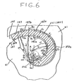
- Figure 6 is an enlarged partial view of a part of a spiral element of a scroll compressor illustrating the configuration of an involute plate member in accordance with a first embodiment of the present invention.
- Figure 7 is an enlarged partial view of a part of a spiral element of a scroll compressor illustrating the configuration of an involute plate member in accordance with a second embodiment of the present invention.
- Figure 8 is an enlarged partial view of a part of a spiral element of a scroll compressor illustrating the configuration of an involute plate member in accordance with a third embodiment of the present invention.
- Figure 9 is an enlarged partial view of a part of a spiral element of a scroll compressor illustrating the configuration of an involute plate member in accordance with a fourth embodiment of the present invention.
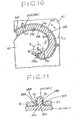
- Figure 10 is an enlarged partial view of a part of a spiral element of a scroll compressor illustrating the configuration of an involute plate member in accordance with a fifth embodiment of the present invention.
- Figure 11 is an enlarged partial sectional view taken along line 11-11 of Figure 10.
- Compressor unit 100 includes compressor housing 10 having front end plate 11 mounted on cup-shaped casing 12.
- An opening 111 is formed in center of front end plate 11 for penetration of drive shaft 13.
- An annular projection 112 is formed in the rear end surface of front end plate 11.
- Annular projection 112 faces cup-shaped casing 12 and is concentric with opening 111.
- An outer peripheral surface of annular projection 112 extends into an inner wall of the opening of cup-shaped casing 12 so that the opening of cup-shaped casing 12 is covered by front end plate 11.
- An O-ring 14 is placed between the outer peripheral surface of annular projection 112 and the inner wall of the opening of cup-shaped casing 12 to seal the mating surface of front end plate 11 and cup-shaped casing 12.
- annular sleeve 15 projects from the front end surface of front end plate 11 to surround drive shaft 13. Annular sleeve 15 defines a shaft seal cavity. In the embodiment shown in Figure 3, sleeve 15 is formed separately from front end plate 11. Therefore, sleeve 15 is fixed to-the front end surface of front end plate 11 by screws (not shown). An O-ring 16 is placed between the end surface of front end plate 11 and an end surface of sleeve 15. Alternatively, sleeve 15 may be formed integrally with front end plate 11.
- Drive shaft 13 is rotatably supported by sleeve 15 through bearing 18, which is located within the front end of sleeve 15.
- Drive shaft 13 has disk 19 at its inner end.
- Disk 19 is rotatably supported by front end plate 11 through bearing 20 located within opening 111 of front end plate 11.
- a shaft seal assembly 21 is coupled to drive shaft 13 within the shaft seal cavity of sleeve 15.
- a pulley 22 is rotatably supported by bearing 23, which is carried on the outer surface of sleeve 15.
- An electromagnetic coil 24 is fixed about the outer surface of sleeve 15 by support plate 25, and is disposed within the annular cavity of pulley 22.
- An armature plate 26 is elastically supported on the outer end of drive shaft 13. Pulley 22, magnetic coil 24 and armature plate 26 form a magnetic clutch.
- drive shaft 13 is driven by an external drive power source, for example, the engine of an automobile, through a rotation transmitting device, such as a magnetic clutch.
- a number of elements are located within the inner chamber of cup-shaped casing 12, including a fixed scroll 27, an orbiting scroll 28, a driving mechanism for orbiting scroll 28 and a rotation preventing/thrust bearing device 35 for orbiting scroll 28.
- the inner chamber of cup-shaped casing 12 is formed between the inner wall of cup-shaped casing 12 and the rear end surface of front end plate 11.
- Fixed scroll 27 includes circular end plate 271, a wrap or spiral element 272 affixed to or extending from one side surface of circular end plate 271, and internally threaded bosses 273 axially projecting from the other end surface of circular plate 271.
- An axial end surface of each boss 273 is seated on the inner surface of bottom plate portion 121 of cup-shaped casing 12 and fixed by screws 37 screwed into bosses 273.
- Circular plate 271 of fixed scroll 27 partitions the inner chamber of cup-shaped casing 12 into a front chamber 29 and rear chamber 30.
- a seal ring 31 is disposed within a circumferential groove of circular end plate 271 to form a seal between the inner wall of cup-shaped casing 12 and the outer surface of circular end plate 271.
- Spiral element 272 of fixed scroll 27 is located within front chamber 29.
- Cup-shaped casing 12 is provided with a fluid inlet port 36 and fluid outlet port 39, which are connected to front and rear chambers 29 and 30, respectively.
- a discharge port 274 is formed through circular plate 271 near the center of spiral element 272.
- a reed valve 38 closes discharge port 274.
- Orbiting scroll 28 which is located in front chamber 29, includes a circular end plate 281 and a wrap or spiral element 282 affixed to or extending from one side surface of circular end plate 281.
- Spiral elements 272 and 282 interfit at an angular offset of 180 degrees and a predetermined radial offset.
- Spiral elements 272 and 282 define at least one pair of sealed off fluid pockets between their interfitting surfaces.
- Orbiting scroll 28 is rotatably supported by bushing 33 through bearing 34 placed between the outer peripheral surface of bushing 33 and the inner surface of annular boss 283 axially projecting from the end surface of circular end plate 281 of orbiting scroll 28.
- Bushing 33 is connected to an inner end of disk 19 at a point radially offset or eccentric with respect to drive shaft 13.
- Rotation preventing/thrust bearing device 35 is disposed between the inner end surface of front end plate 11 and the end surface of circular end plate 281.
- Rotation preventing/thrust bearing device 35 includes fixed ring 351 attached to the inner end surface of front end plate 11, orbiting ring 352 attached to the end surface of circular end plate 281, and a plurality of bearing elements, such as balls 353, placed between the pockets formed by rings 351 and 352.
- the axial thrust load from orbiting scroll 28 also is supported on front end plate 11 through balls 353.
- Spiral elements 272 and 282 include grooves 275 and 285 on the axial end surfaces thereof.
- Seal element 40 is disposed in the grooves to the mating surfaces seal against each circular end plate 271 and 281.
- Involute plate 41 which is formed of a hard metal, such as hardened steel, is fitted to the end surface of both end plates 271 and 281 to minimize the abrasion and reduce the wear of the scrolls.
- the side wall of the spiral element of a scroll follows an involute of a circle such as Figure 4.
- This involute is formed by beginning at starting point P of the generating circle A and tracing the involute from the end of an extensible string unwinding from point P.
- Figure 5 illustrates two involutes, one involute, I, starts at point P on the generating circle A, and the other involute, II, start at point Q on generating circle A.
- the beginning wall of the spiral element of scroll includes a curve, III, which is substantially streamline-shaped and links point Q with point R so as to be convex toward center O of generating circle A.
- Point R lies on the involute in the vicinity of point P, but not exactly on point P.
- involute plate 41 includes slit 141 which has inner edge 142, outer edge 143 and extreme line 144 linking inner edge 142 with outer edge 143.
- Slit 141 is shaped similar to the side walls of spiral elements 272 (282) in order to insert plate 41 over spiral elements 272 (282).
- Slit 141 is designed to be broader in width than spiral elements 272 (282).
- Gaps G1 are created between inner edge 142 and inside wall 272a of spiral element 272 (282), and between outer edge 143 and outside wall 272b of spiral element 272 (282).
- Inner edge 142 and outer edge 143 include first involute portions 142a and 143a towards the center thereof and second involutes 142b and 143b towards the outer ends thereof, respectively.
- First involute portion 142a of inner edge 142 is formed by beginning at starting point Pi of a generating circle A and tracing the involute from the end of an extensible string unwinding from point Pi.
- Second involute portion 142b begins at point P 2 , tracing the involute from the end of an extensible string unwinding from point P 3 and continuing to the end of involute plate 41.
- Point P 3 is located at angular offset of ( ⁇ - ⁇ ) from point P 1 .
- first involute portion 143a of outer edge 143 begins at starting point Q 4 from the end of an extensible string unwinding from point Q 1 of generating circle A.
- First involute portion 143a joins second involute 143b at point Q 2
- Second involute portion 143b is formed by beginning at Q 3 and tracing the involute from the end of an extensible string unwinding from point Q 3 of generating circle A and continuing to the end of involute plate 41.
- Point Q 3 is located at angular offset of ( ⁇ - ⁇ ) from point Q 1 .
- Extreme line 144 of slit 141 of involute plate 41 is preferably a streamline-shaped curve, which is similar in shape to the beginning of end wall 272c of spiral element 272 (282). Extreme line 144 links point P 1 with point Q 4 and is convex toward center O of generating circle A. Point Q 4 lies on first involute 143a in the vicinity of point Q 1 .
- Gap G 1 is created between the inner edge 142 at the first involute portion 142a and the inside wall 272a of spiral element 272, between the outer edge 143 at the first involute portion 143a and the outside wall 272b of spiral element 272, and between extreme line 144 and the beginning of the end wall 272c of the spiral element 272 (282).
- Gap G 0 is created between second involute portion 142b of inner edge 142 and inside wall 272a of spiral element 272, and between second involute portion 143b of outer edge 143 and outside wall 272b of spiral element 272.
- fluid from the external fluid circuit is introduced into fluid pockets in the compressor unit through inlet port 36.
- the fluid in the fluid pockets moves to the center of the spiral elements and is compressed.
- the compressed fluid is discharged into rear chamber 30 through discharge hole 274.
- the compressed fluid then is discharged to the external fluid circuit through outlet port 39.
- First involute portion 142a of inner edge 142 and first involute portion 143a of outer edge 143 of involute plate 41 are sized to avoid contact with the beginning of the end wall 272c of spiral element 272 (282) even if the beginning of the end wall 272c thermally expands.
- FIG. 7 a second embodiment of the present invention is shown which is directed to a modified configuration of involute plate 41.
- This involute plate is similar to involute plate 41 described above. However, some differences do exist as follows.
- Involute plate 41 includes slit 241 which has inner edge 242, outer edge 243 and extreme line 244 linking inner edge 242 with outer edge 243.
- Inner edge 242 begins at point P 3 of circle A and is formed by tracing the involute from the end of an extensible string unwinding from point P 3 .
- the description of outer edge 243 is omitted because it is substantially identical to the first embodiment.
- Extreme line 244 of slit 241 preferably has a streamline-shaped curve, which is similar in shape to the beginning of the end wall 272c of spiral element 272 (282). Extreme line 244 links point P 3 with point Q 4 toward center 0 of generating circle A. Point Q 4 lies on first involute portion 243a towards the center thereof in the vicinity of point Q 1 .
- Gap G 1 is created between first involute portion 243a of outer edge 243 and outside wall 272b of spiral element 272.
- Gap G 0 is created between inner edge 242 and inside wall 272a of spiral element 272.
- Gap G 2 is created between extreme line 244 and the beginning of the end wall 272c of spiral element 272 (282). The size of gap G 2 changes to G 1 at Q 4 and to G 0 at P 3 .
- FIG. 8 a third embodiment of the present invention is shown which is directed to a modified configuration of involute plate 41.
- This involute plate is similar to involute plate 41 described above. However, some differences do exist as follows.
- Involute plate 41 includes slit 341 which has inner edge 342, outer edge 343 and extreme line 344 linking inner edge 342 with outer edge 343.
- the description of inner edge 342 is omitted, since it is substantially identical to that of the first embodiment.
- Outer edge 343 begins at point Q 5 and is formed by tracing the involute from the end of an extensible string unwinding from point Q 3 on circle A.
- Point Q 5 is defined by the point at which length T is tangent to outer edge 343.
- Line T is perpendicular to line L 1 .
- extreme line 344 of slit 341 is preferably a streamline-shaped curve, which is similar in shape to the beginning of the end wall 272c of spiral element 272 (282).
- Extreme line 344 includes first line 344a linking point P 1 with point Q 4 and second line 344b linking point Q 4 with Q 5 .
- Point Q 4 lies on first involute portion 342a towards the center thereof in the vicinity of point Q 1 .
- Gap G 1 is created between the first involute portion 342a and inside wall 272a of spiral element 272 and between first line 344a of extreme line 344 and the beginning of the end wall 272c.
- Gap G 0 is created between second involute portion 342b towards the outer ends thereof and inside wall 272a of spiral element 272.
- Gap G 3 is created between second line 344b of extreme line 344 and the beginning of the end wall 272c of spiral element 272 (282). The size of gap G 3 changes to G 1 at Q 4 and to G 0 at Q 5 .
- a fourth embodiment of the present invention is shown which is directed to a modified configuration of involute plate 41.
- This involute plate is similar to involute plate 41 described above. However, some differences do exist as follows.
- Extreme line 444 links point P 1 with point Q 5 and is convex toward center O of generating circle A.
- Point Q 5 is defined by the point where line T is tangent to first involute portion 443a towards the center thereof of outer edge 443.
- Line T is perpendicular to length L 1 .
- Gap G 4 is created between extreme line 444 and the beginning of the end wall 272c of spiral element 272 (282). Gap G 4 is larger than G 1 .
- involute plate 41 rotates in the direction of arrow.
- Scroll 28 temporally rotates together with involute plate 41, when the compressor is started.
- Extreme line 444 of slit 441 does not contact the edge portion of beginning of the end wall 272c.
- second involute portion 442b and 443b towards the outer ends thereof contact the inside wall 272a or outside wall 272b.
- first involute portion 442a or first involute portion 443a are prevented from striking inside wall 272a, outside wall 272b, or the beginning of the end wall 272c, even if caused by the rotation of involute plate 41.
- a fifth embodiment of the present invention is shown which is directed to a modified configuration of involute plate 41.
- This involute plate is similar to involute plate 41 described above. However, some differences do exist as follows.
- Involute plate 41 includes slit 541 which has inner edge 542, outer edge 543 and extreme line 544 linking inner edge 542 with outer edge 543. Gap G 0 is created between inner edge 542 and inside wall 272a of spiral element 272, between outer edge 543 and outside wall 272b of spiral element 272, and between extreme line 544 and beginning of the end wall of spiral element 272.
- slit 541 is formed by punching. This production process naturally produces beveled curved portions 544 and 545 and C-cut portions 546 and 547.
Landscapes
- Engineering & Computer Science (AREA)
- Mechanical Engineering (AREA)
- General Engineering & Computer Science (AREA)
- Rotary Pumps (AREA)
Claims (9)
- Spiralfluidverdrängungsgerät mit:dadurch gekennzeichnet, daß eine erste Lücke (G1, G2, G3, G4), die zwischen der Zentralkante und einer zentralen konvexen Endwand (272C) als auch zwischen der Innen- und Außenkante und der Innenseiten- und Außenseitenwand (272a, 272b) entlang eines Abschnittes zu dem Zentrum des Spiralelementes (272, 282) gebildet ist, größer als eine zweite Lücke (G0) ist, die zwischen der Innen- und Außenkante und den Spiralelementwänden zu dem äußeren Ende des Spiralelementes (272, 282) gebildet ist.einem Paar von Spiralen (27, 28), wobei jede Spirale eine kreisförmige Endplatte (271, 281) und ein Spiralelement (272, 282) aufweist, das sich von einer axialen Endoberfläche der kreisförmigen Endplatte (271, 281) erstreckt, wobei das Paar von Spiralen (27, 28) mit einer winkelmäßigen und radialen Versetzung zum Herstellen einer Mehrzahl von Linienkontakten gehalten werden, die eine Mehrzahl von abgegrenzten Fluidtaschen definieren;einem Antriebsmechanismus der betriebsmäßig mit einer der Spiralen (28) verbunden ist zum Bewirken einer relativen umlaufenden Bewegung in Bezug auf die andere der Spiralen (27) zum dadurch Ändern des Volumens der Fluidtaschen;einer Involutenplatte (41), die einen darin gebildeten Involutenschlitz (141, 241, 341, 441, 541) enthält, wobei die Spiralelemente (272, 282) in den Involutenschlitz eingeführt sind, die Involutenplatte (41) auf einer axialen Endoberfläche der kreisförmigen Endplatte (271, 281) von beiden der Spiralen (27, 28) vorgesehen ist zum Bedecken der Fläche, auf der der Kontakt gebildet wird mit einer axialen Endoberfläche eines gegenüberliegenden Spiralelementes, der Involutenschlitz eine Innenkante (142, 242, 342, 442, 542), eine Außenkante (143, 243, 343, 443, 543) und eine Zentralkante (144, 244, 344, 444, 544), die die Innenkante mit der Außenkante verbindet, aufweist;
- Spiralfluidverdrängungsgerät nach Anspruch 1, bei dem
die Innenkante und die Außenkante entsprechend erster Abschnitte (242a, 143a, 243a, 342a, 442a, 443a), die sich von der Zentralkante erstrecken, und zweite Abschnitte (142b, 143b, 243b, 342b, 442b, 443b), die sich von den ersten Abschnitten erstrecken, aufweisen, eine erste Lücke (G1) zwischen den ersten Abschnitten der Innen- und der Außenkanten des Involutenschlitzes und der Innenseiten- und Außenseitenwand (272a, 272b) des Spiralelementes (272, 282) gebildet ist, die sich von einer Lücke (G2, G3, G4) unterscheidet, die zwischen der Zentralkante des Involutenschlitzes und einer konvexen Zentralwand (272c) der Spiralelemente gebildet ist, wobei beide diese Lücken größer als die zweite Lücke (G0) sind, die zwischen den zweiten Abschnitten der Innen- und der Außenkanten des Involutenschlitzes und der Wände des Spiralelementes (272, 282) gebildet ist. - Spiralfluidverdrängungsgerät nach Anspruch 1 oder 2, bei dem der Involutenschlitz eine Form ähnlich zu den Seitenwänden des Spiralelementes (272, 282) aufweist.
- Spiralfluidverdrängungsgerät nach Anspruch 2, bei dem jeder der ersten Abschnitte der Innenkante und der Außenkante entsprechend durch Folgen einer Involuten mit einem Ende eines ausdehnbaren Fadens gebildet wird, wobei die ersten Abschnitte der Innenkante und der Außenkante mit den zweiten Abschnitten dort verbunden sind, wo die Länge L1 entlang einer Tangente von dem Erzeugerkreis zu einem Schnittpunkt mit dem ersten Abschnitt L1=2π•r beträgt, wobei r ein Radius des Erzeugerkreises ist.
- Spiralfluidverdrängungsgerät nach einem der Ansprüche 1 bis 4,
bei dem der Involutenschlitz (54) eine angeschrägte Oberfläche (544, 545) aufweist, die an mindestens einer Kante davon gebildet ist. - Spiralfluidverdrängungsgerät nach einem der Ansprüche 1 bis 5, bei dem der Involutenschlitz (541) eine angeschrägte Oberfläche aufweist, die an mindestens einer Ecke davon gebildet ist.
- Spiralfluidverdrängungsgerät nach einem der Ansprüche 2 bis 5, bei dem eine angeschrägte Oberfläche des Involutenschlitzes (541) auf dem ersten Abschnitt der Innen- und/oder Außenkanten, dem zweiten Abschnitt der Innen- und/oder Außenkante und/oder der Zentralkante des Involutenschlitzes (541) gebildet ist.
- Spiralfluidverdrängungsgerät nach einem der Ansprüche 1 bis 5, bei dem eine angeschrägte Oberfläche des Involutenschlitzes (541) nahe einem axialen Ende der kreisförmigen Endplatte (271, 281) der Spiralen (27, 28) angeordnet ist.
- Spiralfluidverdrängungsgerät nach einem der Ansprüche 1 bis 5, bei dem eine angeschrägte Oberfläche des Involutenschlitzes (541) in der Nähe eines Zentrums des Involutenschlitzes (541) gebildet ist.
Applications Claiming Priority (3)
| Application Number | Priority Date | Filing Date | Title |
|---|---|---|---|
| JP7295905A JP3043979B2 (ja) | 1995-10-20 | 1995-10-20 | スクロール型圧縮機用ボトムプレート |
| JP295905/95 | 1995-10-20 | ||
| JP29590595 | 1995-10-20 |
Publications (2)
| Publication Number | Publication Date |
|---|---|
| EP0769623A1 EP0769623A1 (de) | 1997-04-23 |
| EP0769623B1 true EP0769623B1 (de) | 2001-09-12 |
Family
ID=17826674
Family Applications (1)
| Application Number | Title | Priority Date | Filing Date |
|---|---|---|---|
| EP96116576A Expired - Lifetime EP0769623B1 (de) | 1995-10-20 | 1996-10-16 | Spiralanlage zur Fluidverdrängung mit Scheibe zur axialen Dichtung |
Country Status (7)
| Country | Link |
|---|---|
| US (1) | US5791886A (de) |
| EP (1) | EP0769623B1 (de) |
| JP (1) | JP3043979B2 (de) |
| KR (1) | KR100438087B1 (de) |
| AU (1) | AU715323B2 (de) |
| DE (1) | DE69615122T2 (de) |
| PT (1) | PT769623E (de) |
Cited By (1)
| Publication number | Priority date | Publication date | Assignee | Title |
|---|---|---|---|---|
| US6916162B2 (en) | 2003-02-25 | 2005-07-12 | The Boc Group Plc | Scroll compressor |
Families Citing this family (8)
| Publication number | Priority date | Publication date | Assignee | Title |
|---|---|---|---|---|
| JP2003176792A (ja) | 2001-12-10 | 2003-06-27 | Sanden Corp | スクロール型圧縮機 |
| EP1983192A4 (de) * | 2006-01-26 | 2016-08-17 | Daikin Ind Ltd | Verfahren zur herstellung einer schiebekomponente eines kompressors und kompressor |
| JP2007291879A (ja) * | 2006-04-21 | 2007-11-08 | Sanden Corp | スクロール型流体機械 |
| US20120045357A1 (en) * | 2010-08-20 | 2012-02-23 | Po-Chuan Huang | High effieiency scroll compressor with spiral compressor blades of unequal thickness |
| JP5983104B2 (ja) * | 2012-07-03 | 2016-08-31 | アイシン精機株式会社 | スクロール圧縮機 |
| JP6226002B2 (ja) * | 2016-01-26 | 2017-11-08 | ダイキン工業株式会社 | スクロール圧縮機及びそれを備えた空気調和装置 |
| JP6792072B2 (ja) * | 2017-05-15 | 2020-11-25 | 株式会社日立産機システム | スクロール式流体機械 |
| CN117329123B (zh) * | 2023-10-18 | 2026-05-08 | 上海松芝酷恒新能源技术有限公司 | 涡旋式压缩机及涡旋齿型线的修正方法 |
Family Cites Families (21)
| Publication number | Priority date | Publication date | Assignee | Title |
|---|---|---|---|---|
| US801182A (en) | 1905-06-26 | 1905-10-03 | Leon Creux | Rotary engine. |
| US3986799A (en) * | 1975-11-03 | 1976-10-19 | Arthur D. Little, Inc. | Fluid-cooled, scroll-type, positive fluid displacement apparatus |
| JPS5823516B2 (ja) * | 1978-09-04 | 1983-05-16 | サンデン株式会社 | 容積式流体圧縮装置 |
| AU5375079A (en) * | 1978-12-15 | 1980-07-10 | Sankyo Electric Co. Ltd. | Scroll type compressor |
| JPS56147386A (en) * | 1980-04-16 | 1981-11-16 | Nippon Electric Co | Electric high temperature retaining device |
| JPS6041237B2 (ja) * | 1981-03-09 | 1985-09-14 | サンデン株式会社 | スクロ−ル型流体装置 |
| JPS57148086A (en) * | 1981-03-10 | 1982-09-13 | Sanden Corp | Scroll type compressor |
| JPS5823516A (ja) * | 1981-08-01 | 1983-02-12 | Mitsubishi Heavy Ind Ltd | フインチユ−ブの製造方法及びその装置 |
| JPS5851289A (ja) * | 1981-09-22 | 1983-03-25 | Hitachi Ltd | 流体圧縮機 |
| JPS58200092A (ja) * | 1982-05-17 | 1983-11-21 | Hitachi Ltd | スクロ−ル流体機械 |
| JPS58192901A (ja) * | 1983-01-19 | 1983-11-10 | Hitachi Ltd | スクロ−ル流体装置 |
| JPS59142484U (ja) * | 1983-03-15 | 1984-09-22 | サンデン株式会社 | スクロ−ル型流体装置における耐摩耗性板の構造 |
| JPS60175890U (ja) * | 1984-05-02 | 1985-11-21 | 三菱重工業株式会社 | スクロ−ル型流体機械 |
| FR2564198B1 (fr) * | 1984-05-11 | 1986-09-19 | Onera (Off Nat Aerospatiale) | Dispositif d'analyse et de correction de surfaces d'onde en temps reel |
| GB2167133B (en) * | 1984-11-19 | 1988-04-07 | Sanden Corp | Scroll-type rotary fluid-machine |
| JPH0615804B2 (ja) * | 1985-01-25 | 1994-03-02 | 新明和工業株式会社 | スクロ−ル形流体機械 |
| JPH0756274B2 (ja) * | 1987-03-20 | 1995-06-14 | サンデン株式会社 | スクロール式圧縮機 |
| JPS63100288A (ja) * | 1987-08-28 | 1988-05-02 | Matsushita Electric Ind Co Ltd | スクロ−ル流体機械の製造方法 |
| JPH01147181A (ja) * | 1987-12-02 | 1989-06-08 | Toshiba Corp | スクロール流体機械 |
| AU632332B2 (en) * | 1989-06-20 | 1992-12-24 | Sanden Corporation | Scroll type fluid displacement apparatus |
| JPH07139480A (ja) * | 1993-11-15 | 1995-05-30 | Mitsubishi Heavy Ind Ltd | スクロール圧縮機 |
-
1995
- 1995-10-20 JP JP7295905A patent/JP3043979B2/ja not_active Expired - Lifetime
-
1996
- 1996-10-15 AU AU70210/96A patent/AU715323B2/en not_active Expired
- 1996-10-16 DE DE69615122T patent/DE69615122T2/de not_active Expired - Lifetime
- 1996-10-16 EP EP96116576A patent/EP0769623B1/de not_active Expired - Lifetime
- 1996-10-16 PT PT96116576T patent/PT769623E/pt unknown
- 1996-10-17 US US08/733,641 patent/US5791886A/en not_active Expired - Lifetime
- 1996-10-21 KR KR1019960047052A patent/KR100438087B1/ko not_active Expired - Lifetime
Cited By (1)
| Publication number | Priority date | Publication date | Assignee | Title |
|---|---|---|---|---|
| US6916162B2 (en) | 2003-02-25 | 2005-07-12 | The Boc Group Plc | Scroll compressor |
Also Published As
| Publication number | Publication date |
|---|---|
| US5791886A (en) | 1998-08-11 |
| KR100438087B1 (ko) | 2004-07-23 |
| EP0769623A1 (de) | 1997-04-23 |
| PT769623E (pt) | 2002-02-28 |
| JP3043979B2 (ja) | 2000-05-22 |
| AU7021096A (en) | 1997-04-24 |
| DE69615122D1 (de) | 2001-10-18 |
| KR970021752A (ko) | 1997-05-28 |
| JPH09112454A (ja) | 1997-05-02 |
| AU715323B2 (en) | 2000-01-20 |
| DE69615122T2 (de) | 2002-06-13 |
Similar Documents
| Publication | Publication Date | Title |
|---|---|---|
| US4645436A (en) | Scroll type fluid displacement apparatus with improved anti-wear device | |
| US4627800A (en) | Scroll type fluid displacement compressor with spiral wrap elements of varying thickness | |
| US4437820A (en) | Scroll type fluid compressor unit with axial end surface sealing means | |
| EP0060496B1 (de) | Axialspiel-Justiereinrichtung für Fluidverdrängungsanlage vom Exzenterspiralelement-Typ | |
| US4540355A (en) | Axial sealing device for a scroll-type fluid displacement apparatus | |
| EP0227249A1 (de) | Axialdichtungsmechanismus für ein Fluidverdrängungsgerät der Spiralbauweise | |
| CA1323865C (en) | Axial sealing mechanism for a scroll type compressor | |
| US4561832A (en) | Lubricating mechanism for a scroll-type fluid displacement apparatus | |
| US4627799A (en) | Axial sealing mechanism for a scroll type fluid displacement apparatus | |
| US5779461A (en) | Scroll type fluid displacement apparatus having a control system of line contacts between spiral elements | |
| EP0106287A1 (de) | Vorrichtung der Spiralbauart zum Fördern von Fluiden | |
| EP0122723B1 (de) | Einrichtung zum Justieren des Axialspielraumes einer Fluidverdrängermaschine der Spiralbauart | |
| EP0814266B1 (de) | Spiralfluidverdrängungsanlage | |
| US5791886A (en) | Scroll type fluid displacement apparatus with an axial seal plate | |
| EP0065261B1 (de) | Axialdichtung für eine Spiralverdrängermaschine | |
| US5702241A (en) | Scroll-type fluid displacement apparatus having sealing means for central portions of the wraps | |
| US6033194A (en) | Scroll-type fluid displacement apparatus with anti-wear plate mechanism | |
| US4956058A (en) | Scroll type fluid displacement apparatus with surface treated spiral element | |
| EP0350790B1 (de) | Spiralverdichter | |
| EP0075053B1 (de) | Verschleissfeste Mittel für eine Fluidumverdrängungsanlage mit Exzenterspiralelementen | |
| EP0122066A1 (de) | Verdrängermaschine nach dem Spiralprinzip mit einer Einrichtung zum Verhindern der Axial-Bewegung des Antriebslagers | |
| KR19980079773A (ko) | 스크롤형 콤프레서 | |
| US6336798B1 (en) | Rotation preventing mechanism for scroll-type fluid displacement apparatus | |
| KR102510338B1 (ko) | 스크롤 압축기 | |
| CA1259970A (en) | Scroll type fluid displacement apparatus with improved anti-wear device |
Legal Events
| Date | Code | Title | Description |
|---|---|---|---|
| PUAI | Public reference made under article 153(3) epc to a published international application that has entered the european phase |
Free format text: ORIGINAL CODE: 0009012 |
|
| 17P | Request for examination filed |
Effective date: 19970225 |
|
| AK | Designated contracting states |
Kind code of ref document: A1 Designated state(s): DE FR GB IT PT SE |
|
| 17Q | First examination report despatched |
Effective date: 19970821 |
|
| GRAG | Despatch of communication of intention to grant |
Free format text: ORIGINAL CODE: EPIDOS AGRA |
|
| GRAG | Despatch of communication of intention to grant |
Free format text: ORIGINAL CODE: EPIDOS AGRA |
|
| GRAH | Despatch of communication of intention to grant a patent |
Free format text: ORIGINAL CODE: EPIDOS IGRA |
|
| GRAH | Despatch of communication of intention to grant a patent |
Free format text: ORIGINAL CODE: EPIDOS IGRA |
|
| GRAA | (expected) grant |
Free format text: ORIGINAL CODE: 0009210 |
|
| AK | Designated contracting states |
Kind code of ref document: B1 Designated state(s): DE FR GB IT PT SE |
|
| PG25 | Lapsed in a contracting state [announced via postgrant information from national office to epo] |
Ref country code: IT Free format text: LAPSE BECAUSE OF FAILURE TO SUBMIT A TRANSLATION OF THE DESCRIPTION OR TO PAY THE FEE WITHIN THE PRE;WARNING: LAPSES OF ITALIAN PATENTS WITH EFFECTIVE DATE BEFORE 2007 MAY HAVE OCCURRED AT ANY TIME BEFORE 2007. THE CORRECT EFFECTIVE DATE MAY BE DIFFERENT FROM THE ONE RECORDED.SCRIBED TIME-LIMIT Effective date: 20010912 |
|
| PGFP | Annual fee paid to national office [announced via postgrant information from national office to epo] |
Ref country code: SE Payment date: 20011005 Year of fee payment: 6 |
|
| REF | Corresponds to: |
Ref document number: 69615122 Country of ref document: DE Date of ref document: 20011018 |
|
| PG25 | Lapsed in a contracting state [announced via postgrant information from national office to epo] |
Ref country code: SE Free format text: LAPSE BECAUSE OF FAILURE TO SUBMIT A TRANSLATION OF THE DESCRIPTION OR TO PAY THE FEE WITHIN THE PRESCRIBED TIME-LIMIT Effective date: 20011212 |
|
| ET | Fr: translation filed | ||
| REG | Reference to a national code |
Ref country code: GB Ref legal event code: IF02 |
|
| REG | Reference to a national code |
Ref country code: PT Ref legal event code: SC4A Free format text: AVAILABILITY OF NATIONAL TRANSLATION Effective date: 20011119 |
|
| PLBE | No opposition filed within time limit |
Free format text: ORIGINAL CODE: 0009261 |
|
| STAA | Information on the status of an ep patent application or granted ep patent |
Free format text: STATUS: NO OPPOSITION FILED WITHIN TIME LIMIT |
|
| 26N | No opposition filed | ||
| REG | Reference to a national code |
Ref country code: FR Ref legal event code: PLFP Year of fee payment: 20 |
|
| PGFP | Annual fee paid to national office [announced via postgrant information from national office to epo] |
Ref country code: PT Payment date: 20150925 Year of fee payment: 20 |
|
| PGFP | Annual fee paid to national office [announced via postgrant information from national office to epo] |
Ref country code: GB Payment date: 20151021 Year of fee payment: 20 Ref country code: DE Payment date: 20151022 Year of fee payment: 20 |
|
| PGFP | Annual fee paid to national office [announced via postgrant information from national office to epo] |
Ref country code: FR Payment date: 20151023 Year of fee payment: 20 |
|
| REG | Reference to a national code |
Ref country code: DE Ref legal event code: R082 Ref document number: 69615122 Country of ref document: DE Representative=s name: PRUEFER & PARTNER MBB PATENTANWAELTE RECHTSANW, DE Ref country code: DE Ref legal event code: R081 Ref document number: 69615122 Country of ref document: DE Owner name: SANDEN HOLDINGS CORPORATION, LSESAKI-SHI, JP Free format text: FORMER OWNER: SANDEN CORP., ISESAKI, GUNMA, JP |
|
| REG | Reference to a national code |
Ref country code: FR Ref legal event code: CD Owner name: SANDEN HOLDINGS CORPORATION, JP Effective date: 20160525 |
|
| REG | Reference to a national code |
Ref country code: DE Ref legal event code: R071 Ref document number: 69615122 Country of ref document: DE |
|
| REG | Reference to a national code |
Ref country code: GB Ref legal event code: PE20 Expiry date: 20161015 |
|
| PG25 | Lapsed in a contracting state [announced via postgrant information from national office to epo] |
Ref country code: GB Free format text: LAPSE BECAUSE OF EXPIRATION OF PROTECTION Effective date: 20161015 |
|
| PG25 | Lapsed in a contracting state [announced via postgrant information from national office to epo] |
Ref country code: PT Free format text: LAPSE BECAUSE OF EXPIRATION OF PROTECTION Effective date: 20161024 |