EP0770437A1 - Outil d'emboutissage avec support pour platine d'arrachage - Google Patents
Outil d'emboutissage avec support pour platine d'arrachage Download PDFInfo
- Publication number
- EP0770437A1 EP0770437A1 EP96115920A EP96115920A EP0770437A1 EP 0770437 A1 EP0770437 A1 EP 0770437A1 EP 96115920 A EP96115920 A EP 96115920A EP 96115920 A EP96115920 A EP 96115920A EP 0770437 A1 EP0770437 A1 EP 0770437A1
- Authority
- EP
- European Patent Office
- Prior art keywords
- stripper plate
- punching tool
- punch
- punching
- tool according
- Prior art date
- Legal status (The legal status is an assumption and is not a legal conclusion. Google has not performed a legal analysis and makes no representation as to the accuracy of the status listed.)
- Granted
Links
- 238000004080 punching Methods 0.000 title claims description 29
- 230000002093 peripheral effect Effects 0.000 claims description 2
- 230000000881 depressing effect Effects 0.000 claims 1
- 230000002787 reinforcement Effects 0.000 abstract 1
- 239000011324 bead Substances 0.000 description 5
- 238000006073 displacement reaction Methods 0.000 description 2
- 235000018453 Curcuma amada Nutrition 0.000 description 1
- 241001512940 Curcuma amada Species 0.000 description 1
- 230000007246 mechanism Effects 0.000 description 1
- 238000000034 method Methods 0.000 description 1
Images

Classifications
-
- B—PERFORMING OPERATIONS; TRANSPORTING
- B21—MECHANICAL METAL-WORKING WITHOUT ESSENTIALLY REMOVING MATERIAL; PUNCHING METAL
- B21D—WORKING OR PROCESSING OF SHEET METAL OR METAL TUBES, RODS OR PROFILES WITHOUT ESSENTIALLY REMOVING MATERIAL; PUNCHING METAL
- B21D45/00—Ejecting or stripping-off devices arranged in machines or tools dealt with in this subclass
- B21D45/003—Ejecting or stripping-off devices arranged in machines or tools dealt with in this subclass in punching machines or punching tools
- B21D45/006—Stripping-off devices
Definitions
- the invention relates to a punching tool with a guide bushing which receives a punch which can be dismantled downwards and carries a stripper plate which can be fixed in the engagement area of the punching punch by holding members to be attached to the guide bushing and can be removed axially from the punching punch after the holding members have been released.
- the stripper plate is inserted into the guide bushing over the already installed punching punch and secured in the axial direction with the aid of retaining plates which are screwed onto the guide bushing.
- punching tools it is often necessary to replace the punch and / or the stripper plate during operation. For this purpose, it is always necessary to remove all the holding plates, which has proven to be very cumbersome and time-consuming, not least because of the small and therefore difficult-to-handle fastening screws.
- a simple mounting of the scraper plate is known from punching tools, in which the punch is removed upward from the guide bush.
- the scraper plate is inserted into a guide that is open on the side, so that it is free after removal of the punch and can therefore be easily removed.
- the stripper plate since in a punching tool of the type described in the introduction, the stripper plate must first be removed so that the punch can also be removed, such a holder cannot be used here.
- the object of the invention is to provide a punching tool of the type described at the outset, which has a holder for the stripper plate, which enables the stripper plate and the punch to be removed much more quickly and easily.
- the object is achieved in that the holding members are movably mounted on the guide bushing and are movable between a position that locks the stripper plate and a position that releases it.
- the stripper plate is received by a movable holding device which can be disengaged from the engagement area of the stamp into a position in the punching direction from the operating position of the stripper plate, in which the holding members lock the stripper plate and the holding device which the stripper plate can be removed from the side from a guide attached to the holding device and which centers the stripper plate relative to the guide bush.
- the movable holding device makes it easier to insert the scraper plate because it centers the scraper plate on the guide when it is inserted laterally to the guide bush and makes it easier for the fitter to thread the tightly fitting stripper plate onto the punch.
- An elastic element expediently supports the disengagement movement of the holding device. As a result, after the holding members have been actuated, the holding device jumps away from the guide bush with the wiper plate downward. Without this support of the disengagement movement, it would be necessary to grip the holding device or the stripper plate and pull it away from the guide bush.
- the holding members are rocker arms with holding lugs, by their one-sided pressing against a spring force the stripper plate and thus the holding device can be unlocked.
- the advantage of the rocker arm is its easy handling.
- the holding members expediently have safeguards against unintentional opening.
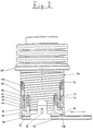
- FIG. 1 shows a punching tool 10 for a turret punch made by Amada. It essentially consists of a guide bush 12, a punch (not shown) accommodated therein, a punch driver, of which only a stamp driver head 14 can be seen in FIG. 1, and a stripper plate 16 which is attached to the guide bush 12 via a holding device 18 is. Between the punch driver head 14 and an edge flange 20 belonging to the guide bushing 12, a plurality of series springs 22 are provided, which move the punch back into its starting position after the punching process.
- the wiper plate 16 has on its outer circumference an annular groove 24 which is guided on a guide bead 26 (FIG. 2) extending over 180 ° and is held centrally in the holding device 18.
- the holding device 18 is in turn guided with axial projections in two diametrically opposite, groove-like recesses 28 in the guide bushing 12, which enable the holder to be axially displaceable in the punching direction.
- the displacement path of the holding device 18 is limited by a stop bolt 30 in each recess 28, which is fastened to the guide bush 12 transversely to the punching direction and engages in an axially extending groove 32 in each projection of the holding device 18.
- the wiper plate 16 and the holding device 18 are axially immovably held by two diametrically opposed rocker arms 34 with holding lugs 36 which engage in the annular groove 24.
- One of the rocker arms 34 is arranged in the middle of the opening of the guide bead 26, which extends in a horseshoe shape over 180 ° of the circumference of the stripper plate 16, the other engages through a recess corresponding to its width in the peripheral wall of the Holder device 18 into the annular groove 24. Possibly. more holding members can also be provided. This can improve grip, but handling becomes more difficult.
- An annular part 38 of the holding device 18 lies in the closed state of the holder 18 on the underside of the guide bush 12 and thereby ensures an exact positioning of the wiper plate 16.
- the rocker arms 34 are pivotable about a pivot bearing 40, so that by pressing the rocker arm 34 against the force of a locking spring 42, the retaining lugs 36 located on the other side of the pivot bearing 40 can be moved radially outward into a position that releases the stripper plate 16.
- a locking member 44 which is axially displaceable in the tool direction is provided on each rocker arm 34, which engages with a locking shoulder 46 under the actuating side of the rocker arm 34 and blocks it.
- the securing member 44 is preloaded in the direction of the closed position by a spring 48.
- an unlocking slide 50 is provided, which is arranged on the actuating side of the rocker arm 34 so as to be displaceable in the direction of displacement of the securing member 44.
- the unlocking slide 50 has a U-shaped profile and engages a projection 52 of the securing member 44.
- the unlocking slide 50 does not hinder the depression of the rocker arm 34 when the securing member 44 has been moved over the projection 52 into a position which is free of the rocker arm 34.
- the stripper plate 16 is removed in such a way that the locking member 44 is first moved with the unlocking slide 50 until the locking shoulder 46 releases the rocker arm 34. Now the rocker arm 34 can be pivoted about the pivot bearing 40 against the force of the locking spring 42, so that the retaining lugs 36 release the wiper plate 16.
- the position of the unlocking slide 50 on the rocker arm 34 allows easy handling, since both the unlocking and the actuation of the rocker arm can be carried out with one finger. Accidental triggering of the rocker arm 34, for example by an impact, is not possible.
- release springs 54 via ejection bolts 56 ensure that the holding device 18 disengages with the wiper plate 16 downward from the guide bush 12 (see FIG. 2).
- the disengagement movement of the holding device 18 is limited by the stop bolt 30, which bears against the upper end of the groove 32.
- the annular part 38 holds the rocker arms 34 in their open position so that they do not hinder the later pushing in of the holding device.
- the guide bead 26 in the holding device 18 comprises the scraper plate 16 in a horseshoe shape, ie only over its half circumference, so that in the disengaged position of the holding device 18 it moves laterally out of the opening of the horseshoe-shaped guide bead 26, axially at the end of the one, in the area of the opening arranged rocker arm 34 is pulled out.
- the holding device 18 must at least move out of the guide bush 12 so that the stripper plate 16 is no longer in the engagement area of the punch.
- stripper plate 16 After the stripper plate 16 has been removed, it can also be removed.
- the punching tool 10 is assembled in the reverse direction. After the punch has been installed in the guide bushing 12, the stripper plate 16 is pushed laterally into the guide bead 26 of the holding device 18 until in the end position it assumes a position centered with respect to the guide bushing 12. The holding device is then pushed against the force of the release springs 54 against the guide bush 12. When the final position of the wiper plate 16 is reached, the rocker arms 34 snap into the annular groove 24 of the wiper plate 16 with their retaining lugs 36 due to the force of the locking springs 42. At the same time, the springs 48 press the locking members 44 with their shoulders 46 under the rocker arms, so that the wiper plate 16 is locked and secured.
Landscapes
- Engineering & Computer Science (AREA)
- Mechanical Engineering (AREA)
- Punching Or Piercing (AREA)
- Perforating, Stamping-Out Or Severing By Means Other Than Cutting (AREA)
Applications Claiming Priority (2)
| Application Number | Priority Date | Filing Date | Title |
|---|---|---|---|
| DE19539777 | 1995-10-26 | ||
| DE19539777A DE19539777A1 (de) | 1995-10-26 | 1995-10-26 | Stanzwerkzeug mit Halterung für Abstreiferplatte |
Publications (2)
| Publication Number | Publication Date |
|---|---|
| EP0770437A1 true EP0770437A1 (fr) | 1997-05-02 |
| EP0770437B1 EP0770437B1 (fr) | 2001-06-20 |
Family
ID=7775773
Family Applications (1)
| Application Number | Title | Priority Date | Filing Date |
|---|---|---|---|
| EP96115920A Expired - Lifetime EP0770437B1 (fr) | 1995-10-26 | 1996-10-04 | Outil d'emboutissage avec support pour platine d'arrachage |
Country Status (3)
| Country | Link |
|---|---|
| EP (1) | EP0770437B1 (fr) |
| AT (1) | ATE202303T1 (fr) |
| DE (2) | DE19539777A1 (fr) |
Cited By (2)
| Publication number | Priority date | Publication date | Assignee | Title |
|---|---|---|---|---|
| WO2003103872A1 (fr) * | 2002-06-07 | 2003-12-18 | Wilson Tool International, Inc. | Systeme de retenue ameliore pour plaque d'ejection |
| JP2006167746A (ja) * | 2004-12-15 | 2006-06-29 | Amada Co Ltd | パンチ金型組立体 |
Citations (5)
| Publication number | Priority date | Publication date | Assignee | Title |
|---|---|---|---|---|
| US4248111A (en) * | 1979-07-16 | 1981-02-03 | Wilson Tool Company | Punch guide assembly |
| FR2475950A1 (fr) * | 1980-02-15 | 1981-08-21 | Behrens Ag C | Dispositif pour maintenir un devetisseur interchangeable sur le porte-outil d'un outil de formage sans enlevement de copeau, et outil pour le changement du devetisseur |
| EP0628364A1 (fr) * | 1993-06-07 | 1994-12-14 | Amada Metrecs Company, Limited | Outil de poinçonnage |
| EP0640417A1 (fr) * | 1993-07-30 | 1995-03-01 | Amada Metrecs Company, Limited | Outil supérieur pour une presse |
| EP0644005A2 (fr) * | 1993-02-03 | 1995-03-22 | Amada Metrecs Company, Limited | Outil de poinçonnage |
-
1995
- 1995-10-26 DE DE19539777A patent/DE19539777A1/de not_active Withdrawn
-
1996
- 1996-10-04 EP EP96115920A patent/EP0770437B1/fr not_active Expired - Lifetime
- 1996-10-04 DE DE59607125T patent/DE59607125D1/de not_active Expired - Fee Related
- 1996-10-04 AT AT96115920T patent/ATE202303T1/de not_active IP Right Cessation
Patent Citations (5)
| Publication number | Priority date | Publication date | Assignee | Title |
|---|---|---|---|---|
| US4248111A (en) * | 1979-07-16 | 1981-02-03 | Wilson Tool Company | Punch guide assembly |
| FR2475950A1 (fr) * | 1980-02-15 | 1981-08-21 | Behrens Ag C | Dispositif pour maintenir un devetisseur interchangeable sur le porte-outil d'un outil de formage sans enlevement de copeau, et outil pour le changement du devetisseur |
| EP0644005A2 (fr) * | 1993-02-03 | 1995-03-22 | Amada Metrecs Company, Limited | Outil de poinçonnage |
| EP0628364A1 (fr) * | 1993-06-07 | 1994-12-14 | Amada Metrecs Company, Limited | Outil de poinçonnage |
| EP0640417A1 (fr) * | 1993-07-30 | 1995-03-01 | Amada Metrecs Company, Limited | Outil supérieur pour une presse |
Cited By (5)
| Publication number | Priority date | Publication date | Assignee | Title |
|---|---|---|---|---|
| WO2003103872A1 (fr) * | 2002-06-07 | 2003-12-18 | Wilson Tool International, Inc. | Systeme de retenue ameliore pour plaque d'ejection |
| US6895849B2 (en) | 2002-06-07 | 2005-05-24 | Wilson Tool International, Inc. | Stripper plate retention system |
| CN100346897C (zh) * | 2002-06-07 | 2007-11-07 | 威尔逊国际工具公司 | 改良的脱模板保持系统 |
| AU2003238942B2 (en) * | 2002-06-07 | 2009-04-30 | Wilson Tool International, Inc. | Improved stripper plate retention system |
| JP2006167746A (ja) * | 2004-12-15 | 2006-06-29 | Amada Co Ltd | パンチ金型組立体 |
Also Published As
| Publication number | Publication date |
|---|---|
| DE19539777A1 (de) | 1997-04-30 |
| ATE202303T1 (de) | 2001-07-15 |
| DE59607125D1 (de) | 2001-07-26 |
| EP0770437B1 (fr) | 2001-06-20 |
Similar Documents
| Publication | Publication Date | Title |
|---|---|---|
| DE2746921C3 (de) | Vorrichtung und Verfahren zur Herstellung von Verbindungen in und zur Prüfung von pneumatischen und hydraulischen Systemen | |
| EP0468335B1 (fr) | Outil pour le sertissage d'un connecteur à un conducteur et une isolation | |
| DE69003417T2 (de) | Haltevorrichtung für ein längliches Werkstück, wie ein Stempel, eine Matrize oder ein ähnliches Werkzeug auf einem Werktisch einer Abkantpresse. | |
| DE4211276A1 (de) | Haltevorrichtung für Fügeteile | |
| DE2511490A1 (de) | Vorrichtung zum aufweiten von rohrleitungsenden | |
| DE3136440A1 (de) | Spannvorrichtung zum spannen von werkzeugen | |
| DE69612790T2 (de) | Bedienungstaste mit Verriegelung, insbesondere zur Bedienung einer elektrische Komponente | |
| DE69501712T2 (de) | Zug-druck Bedienungstaste mit Verriegelung insbesondere zur Bedienung einer elektrischen Komponente | |
| EP1188936B1 (fr) | Assemblage de connection pour la fixation amovible de deux éléments | |
| EP0755749A1 (fr) | Dispositif de guidage et/ou de fixation pour éléments, particulièrement pour éléments de fixation | |
| DE3436075C1 (de) | Vorrichtung zur Ioesbaren Verbindung von Greiferschienenteilen der Greiferschienen in einer Transfer-Presse | |
| EP0645213B1 (fr) | Dispositif pour le positionnement d'une palette à localisation prédéterminée sur une table de serrage | |
| DE3604115C2 (de) | Türdrückeranordnung | |
| DE3423543A1 (de) | Presse und verfahren zur herstellung derselben | |
| EP0193081A2 (fr) | Poignée de porte | |
| EP2156060B1 (fr) | Dispositif de fixation permettant d'assembler un profilé et un contre-profilé de façon libérable | |
| EP1206734B1 (fr) | Boitier de clavier pour les touches d'un clavier a touches a enfoncer | |
| DE3335329A1 (de) | Werkzeugmaschine, insbesondere revolverschneidpresse mit fuer einen ferngesteuerten wechsel geeigneter werkzeugaufnahme | |
| EP0770437B1 (fr) | Outil d'emboutissage avec support pour platine d'arrachage | |
| EP1366873B1 (fr) | Détoureuse | |
| EP0965699A1 (fr) | Dispositif pour le montage coulissant d'un article, en particulier une pomme de douche sur une barre de support | |
| DE3327676C2 (fr) | ||
| DE4122567C2 (fr) | ||
| EP0253118B1 (fr) | Fourchette pour commande d'un embrayage de véhicule | |
| DE69803638T2 (de) | Kupplungssteuerungsvorrichtung |
Legal Events
| Date | Code | Title | Description |
|---|---|---|---|
| PUAI | Public reference made under article 153(3) epc to a published international application that has entered the european phase |
Free format text: ORIGINAL CODE: 0009012 |
|
| AK | Designated contracting states |
Kind code of ref document: A1 Designated state(s): AT BE CH DE DK ES FI FR GB IT LI NL SE |
|
| 17P | Request for examination filed |
Effective date: 19970918 |
|
| 17Q | First examination report despatched |
Effective date: 20000324 |
|
| GRAG | Despatch of communication of intention to grant |
Free format text: ORIGINAL CODE: EPIDOS AGRA |
|
| GRAG | Despatch of communication of intention to grant |
Free format text: ORIGINAL CODE: EPIDOS AGRA |
|
| GRAH | Despatch of communication of intention to grant a patent |
Free format text: ORIGINAL CODE: EPIDOS IGRA |
|
| GRAH | Despatch of communication of intention to grant a patent |
Free format text: ORIGINAL CODE: EPIDOS IGRA |
|
| GRAA | (expected) grant |
Free format text: ORIGINAL CODE: 0009210 |
|
| AK | Designated contracting states |
Kind code of ref document: B1 Designated state(s): AT BE CH DE DK ES FI FR GB IT LI NL SE |
|
| PG25 | Lapsed in a contracting state [announced via postgrant information from national office to epo] |
Ref country code: NL Free format text: LAPSE BECAUSE OF FAILURE TO SUBMIT A TRANSLATION OF THE DESCRIPTION OR TO PAY THE FEE WITHIN THE PRESCRIBED TIME-LIMIT Effective date: 20010620 Ref country code: IT Free format text: LAPSE BECAUSE OF FAILURE TO SUBMIT A TRANSLATION OF THE DESCRIPTION OR TO PAY THE FEE WITHIN THE PRE;WARNING: LAPSES OF ITALIAN PATENTS WITH EFFECTIVE DATE BEFORE 2007 MAY HAVE OCCURRED AT ANY TIME BEFORE 2007. THE CORRECT EFFECTIVE DATE MAY BE DIFFERENT FROM THE ONE RECORDED.SCRIBED TIME-LIMIT Effective date: 20010620 Ref country code: GB Free format text: LAPSE BECAUSE OF FAILURE TO SUBMIT A TRANSLATION OF THE DESCRIPTION OR TO PAY THE FEE WITHIN THE PRESCRIBED TIME-LIMIT Effective date: 20010620 Ref country code: FR Free format text: LAPSE BECAUSE OF FAILURE TO SUBMIT A TRANSLATION OF THE DESCRIPTION OR TO PAY THE FEE WITHIN THE PRESCRIBED TIME-LIMIT Effective date: 20010620 Ref country code: FI Free format text: LAPSE BECAUSE OF FAILURE TO SUBMIT A TRANSLATION OF THE DESCRIPTION OR TO PAY THE FEE WITHIN THE PRESCRIBED TIME-LIMIT Effective date: 20010620 |
|
| REF | Corresponds to: |
Ref document number: 202303 Country of ref document: AT Date of ref document: 20010715 Kind code of ref document: T |
|
| REG | Reference to a national code |
Ref country code: CH Ref legal event code: EP |
|
| REF | Corresponds to: |
Ref document number: 59607125 Country of ref document: DE Date of ref document: 20010726 |
|
| PG25 | Lapsed in a contracting state [announced via postgrant information from national office to epo] |
Ref country code: SE Free format text: LAPSE BECAUSE OF FAILURE TO SUBMIT A TRANSLATION OF THE DESCRIPTION OR TO PAY THE FEE WITHIN THE PRESCRIBED TIME-LIMIT Effective date: 20010920 Ref country code: DK Free format text: LAPSE BECAUSE OF FAILURE TO SUBMIT A TRANSLATION OF THE DESCRIPTION OR TO PAY THE FEE WITHIN THE PRESCRIBED TIME-LIMIT Effective date: 20010920 |
|
| PG25 | Lapsed in a contracting state [announced via postgrant information from national office to epo] |
Ref country code: AT Free format text: LAPSE BECAUSE OF NON-PAYMENT OF DUE FEES Effective date: 20011004 |
|
| PG25 | Lapsed in a contracting state [announced via postgrant information from national office to epo] |
Ref country code: LI Free format text: LAPSE BECAUSE OF NON-PAYMENT OF DUE FEES Effective date: 20011031 Ref country code: CH Free format text: LAPSE BECAUSE OF NON-PAYMENT OF DUE FEES Effective date: 20011031 Ref country code: BE Free format text: LAPSE BECAUSE OF NON-PAYMENT OF DUE FEES Effective date: 20011031 |
|
| NLV1 | Nl: lapsed or annulled due to failure to fulfill the requirements of art. 29p and 29m of the patents act | ||
| GBV | Gb: ep patent (uk) treated as always having been void in accordance with gb section 77(7)/1977 [no translation filed] |
Effective date: 20010620 |
|
| PG25 | Lapsed in a contracting state [announced via postgrant information from national office to epo] |
Ref country code: ES Free format text: LAPSE BECAUSE OF FAILURE TO SUBMIT A TRANSLATION OF THE DESCRIPTION OR TO PAY THE FEE WITHIN THE PRESCRIBED TIME-LIMIT Effective date: 20011220 |
|
| EN | Fr: translation not filed | ||
| PGFP | Annual fee paid to national office [announced via postgrant information from national office to epo] |
Ref country code: DE Payment date: 20011221 Year of fee payment: 6 |
|
| PLBE | No opposition filed within time limit |
Free format text: ORIGINAL CODE: 0009261 |
|
| STAA | Information on the status of an ep patent application or granted ep patent |
Free format text: STATUS: NO OPPOSITION FILED WITHIN TIME LIMIT |
|
| BERE | Be: lapsed |
Owner name: MATE PRECISION TOOLING G.M.B.H. Effective date: 20011031 |
|
| 26N | No opposition filed | ||
| REG | Reference to a national code |
Ref country code: CH Ref legal event code: PL |
|
| PG25 | Lapsed in a contracting state [announced via postgrant information from national office to epo] |
Ref country code: DE Free format text: LAPSE BECAUSE OF NON-PAYMENT OF DUE FEES Effective date: 20030501 |