EP0770489A1 - Dispositif pour la rétention de l'encre dans une imprimante par jet d'encre - Google Patents
Dispositif pour la rétention de l'encre dans une imprimante par jet d'encre Download PDFInfo
- Publication number
- EP0770489A1 EP0770489A1 EP96302191A EP96302191A EP0770489A1 EP 0770489 A1 EP0770489 A1 EP 0770489A1 EP 96302191 A EP96302191 A EP 96302191A EP 96302191 A EP96302191 A EP 96302191A EP 0770489 A1 EP0770489 A1 EP 0770489A1
- Authority
- EP
- European Patent Office
- Prior art keywords
- fluid storage
- ink
- storage medium
- channels
- foam
- Prior art date
- Legal status (The legal status is an assumption and is not a legal conclusion. Google has not performed a legal analysis and makes no representation as to the accuracy of the status listed.)
- Granted
Links
- 239000012530 fluid Substances 0.000 claims abstract description 39
- 238000004891 communication Methods 0.000 claims abstract description 6
- 238000003860 storage Methods 0.000 claims description 36
- 239000011148 porous material Substances 0.000 claims description 23
- 238000000034 method Methods 0.000 claims description 3
- 239000006260 foam Substances 0.000 abstract description 111
- 229920006395 saturated elastomer Polymers 0.000 description 11
- 238000009950 felting Methods 0.000 description 6
- 230000007423 decrease Effects 0.000 description 3
- 230000000694 effects Effects 0.000 description 3
- 238000004519 manufacturing process Methods 0.000 description 3
- 239000003086 colorant Substances 0.000 description 2
- 230000006835 compression Effects 0.000 description 2
- 238000007906 compression Methods 0.000 description 2
- 238000005429 filling process Methods 0.000 description 2
- 239000007788 liquid Substances 0.000 description 2
- 206010013642 Drooling Diseases 0.000 description 1
- JOYRKODLDBILNP-UHFFFAOYSA-N Ethyl urethane Chemical compound CCOC(N)=O JOYRKODLDBILNP-UHFFFAOYSA-N 0.000 description 1
- 208000008630 Sialorrhea Diseases 0.000 description 1
- WYTGDNHDOZPMIW-RCBQFDQVSA-N alstonine Natural products C1=CC2=C3C=CC=CC3=NC2=C2N1C[C@H]1[C@H](C)OC=C(C(=O)OC)[C@H]1C2 WYTGDNHDOZPMIW-RCBQFDQVSA-N 0.000 description 1
- 238000011109 contamination Methods 0.000 description 1
- 230000003247 decreasing effect Effects 0.000 description 1
- 238000009792 diffusion process Methods 0.000 description 1
- 238000006073 displacement reaction Methods 0.000 description 1
- 230000002209 hydrophobic effect Effects 0.000 description 1
- 229920002635 polyurethane Polymers 0.000 description 1
- 239000004814 polyurethane Substances 0.000 description 1
- 238000009738 saturating Methods 0.000 description 1
- 238000013022 venting Methods 0.000 description 1
- 239000011800 void material Substances 0.000 description 1
Images



Classifications
-
- B—PERFORMING OPERATIONS; TRANSPORTING
- B41—PRINTING; LINING MACHINES; TYPEWRITERS; STAMPS
- B41J—TYPEWRITERS; SELECTIVE PRINTING MECHANISMS, i.e. MECHANISMS PRINTING OTHERWISE THAN FROM A FORME; CORRECTION OF TYPOGRAPHICAL ERRORS
- B41J2/00—Typewriters or selective printing mechanisms characterised by the printing or marking process for which they are designed
- B41J2/005—Typewriters or selective printing mechanisms characterised by the printing or marking process for which they are designed characterised by bringing liquid or particles selectively into contact with a printing material
- B41J2/01—Ink jet
- B41J2/17—Ink jet characterised by ink handling
- B41J2/175—Ink supply systems ; Circuit parts therefor
- B41J2/17503—Ink cartridges
- B41J2/17513—Inner structure
-
- B—PERFORMING OPERATIONS; TRANSPORTING
- B41—PRINTING; LINING MACHINES; TYPEWRITERS; STAMPS
- B41J—TYPEWRITERS; SELECTIVE PRINTING MECHANISMS, i.e. MECHANISMS PRINTING OTHERWISE THAN FROM A FORME; CORRECTION OF TYPOGRAPHICAL ERRORS
- B41J2/00—Typewriters or selective printing mechanisms characterised by the printing or marking process for which they are designed
- B41J2/005—Typewriters or selective printing mechanisms characterised by the printing or marking process for which they are designed characterised by bringing liquid or particles selectively into contact with a printing material
- B41J2/01—Ink jet
- B41J2/17—Ink jet characterised by ink handling
- B41J2/175—Ink supply systems ; Circuit parts therefor
- B41J2/17503—Ink cartridges
- B41J2/17526—Electrical contacts to the cartridge
-
- B—PERFORMING OPERATIONS; TRANSPORTING
- B41—PRINTING; LINING MACHINES; TYPEWRITERS; STAMPS
- B41J—TYPEWRITERS; SELECTIVE PRINTING MECHANISMS, i.e. MECHANISMS PRINTING OTHERWISE THAN FROM A FORME; CORRECTION OF TYPOGRAPHICAL ERRORS
- B41J2/00—Typewriters or selective printing mechanisms characterised by the printing or marking process for which they are designed
- B41J2/005—Typewriters or selective printing mechanisms characterised by the printing or marking process for which they are designed characterised by bringing liquid or particles selectively into contact with a printing material
- B41J2/01—Ink jet
- B41J2/17—Ink jet characterised by ink handling
- B41J2/175—Ink supply systems ; Circuit parts therefor
- B41J2/17503—Ink cartridges
- B41J2/17553—Outer structure
-
- B—PERFORMING OPERATIONS; TRANSPORTING
- B41—PRINTING; LINING MACHINES; TYPEWRITERS; STAMPS
- B41J—TYPEWRITERS; SELECTIVE PRINTING MECHANISMS, i.e. MECHANISMS PRINTING OTHERWISE THAN FROM A FORME; CORRECTION OF TYPOGRAPHICAL ERRORS
- B41J2/00—Typewriters or selective printing mechanisms characterised by the printing or marking process for which they are designed
- B41J2/005—Typewriters or selective printing mechanisms characterised by the printing or marking process for which they are designed characterised by bringing liquid or particles selectively into contact with a printing material
- B41J2/01—Ink jet
- B41J2/17—Ink jet characterised by ink handling
- B41J2/175—Ink supply systems ; Circuit parts therefor
- B41J2/17503—Ink cartridges
- B41J2/17556—Means for regulating the pressure in the cartridge
Definitions
- the present invention is directed to a foam-based ink containment system for an ink-jet printer.
- An ink-jet printer includes a pen in which small droplets of ink are formed and ejected from the printer pen toward a printing medium.
- Such pens include printheads with orifice plates with several very small nozzles through which the ink droplets are ejected.
- Adjacent to the nozzles are ink chambers, where ink is stored prior to ejection through the nozzle.
- Ink is delivered to the ink chambers through ink channels in fluid communication with an ink supply.
- the ink supply may be, for example, contained in a reservoir part of the pen.
- ink delivery For color printing, multiple colors are made available to the printer. For each color of ink there is a separate ink reservoir and ink delivery system coupled to a separate group of ink chambers and nozzles. In order to achieve high quality, high resolution printing, these groups of nozzles are placed relatively close together on the printhead. Control of ink flow is required to prevent excess ink from being delivered to the printhead. Excess ink delivery leads to leakage, or drooling from the nozzles.
- Ink-jet printer systems are affected by changes in ambient conditions, such as temperature and pressure.
- ambient conditions such as temperature and pressure.
- air diffused throughout the ink and air bubbles present within the ink reservoir expand to cause displacement of ink.
- the displaced ink is forced out the printhead nozzles resulting in undesired drool.
- one color of ink may migrate across the surface of the printhead to another color group.
- the migrated ink may be sucked back into the nozzles of another color ink.
- the mixing of these two ink colors causes contamination, producing poor quality printing.
- Open cell foam is often used to store ink within a reservoir of an ink-jet pen.
- the top of the reservoir may be vented to ambient to allow equalization of pressure within the ink container to the outside air pressure.
- substantially all of the exterior surfaces of conventional foam ink storage members are in contact with the walls of the pen reservoir. Such contact between ink saturated foam and the reservoir walls creates a seal through which air is unable to pass for venting to atmosphere.
- the expanded trapped air displaces ink and causes drool through the nozzles.
- Felting is a measure of the extent to which foam is compressed. Compressing the foam decreases the pore dimensions. By increasing the felting of the foam (i.e., the amount of compression of the foam), pore size decreases and capillary force increases. A greater capillary force increases back pressure within the reservoir. An increase in back pressure within the reservoir helps to prevent drool.
- extra felting of the foam does not aid removal of air trapped within the foam. Extra felting also reduces the foam's ink storage capacity. Moreover, extra felting makes manufacturing difficult, as the foam is difficult to insert in the necessarily small reservoir.
- Grooved reservoir walls have been used to prevent ink drool.
- the grooves create a series of interconnected channels between the foam member and the reservoir walls. Expanding air from the foam's interior diffuses into these channels and is vented out of the reservoir.
- the grooved reservoir walls can be difficult to manufacture. Additionally, grooved reservoir walls can make the walls more flexible, and the pressure exerted by the compressed foam can deform the flexible reservoir walls so that the ink-jet pen does not fit properly within the printer.
- the present invention is directed to a system for storing ink in a pen reservoir, while preventing ink leakage due to a change in ambient temperature or pressure.
- the system comprises a porous grooved foam.
- the porous foam is grooved on the exterior portion to provide paths for air to move to the atmosphere. Thus, air within the interior portion of the foam may expand to the grooves on the exterior portion.
- An atmospheric vent is in fluid communication with at least one of the grooves, thereby to vent excess air within the reservoir.
- the grooved foam may be used in any of a variety of ink-jet pen reservoirs and may be implemented with any foam based pen.
- Fig. 1 is a perspective view of an ink-jet printer pen constructed in accordance with the invention.
- Fig. 2 is cross-sectional side view of the apparatus in Fig. 1 taken along line 2-2.
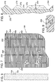
- Fig. 3 is an end view of the foam member of the present invention.
- Fig. 4 is an enlarged partial side view of the foam constructed in accordance with a preferred embodiment of the present invention.
- Fig. 5 is an enlarged cross-sectional side view of the foam in Fig. 4 taken along line 5-5.
- Fig. 6 is an enlarged cross-sectional view of the foam in Fig. 4 taken along line 6-6.
- Fig. 7 is a side view of the foam constructed in accordance with another preferred embodiment of the present invention.
- Fig. 8 is an enlarged cross-sectional view of the foam of Fig. 7 taken along line 8-8.
- Fig. 9 is an enlarged cross-sectional view of the foam of Fig. 7 taken along line 9-9.
- Fig. 1 shows a three-color ink-jet cartridge 10 having a box shaped body 12.
- a printhead 20 is attached to the bottom of the pen body 12 (Fig. 2).
- the printhead 20 defines three separate sets of print orifices (not shown) that provide apertures for expelling ink in a controlled pattern during printing.
- the printhead 20 is electronically controlled through a connector circuit 24 mounted on the body 12.
- the body 12 defines three similar sized adjacent ink chambers 26a, 26b, 26c (also referred to herein as reservoirs).
- a side cover 32, 34 each of which forms a respective wall of ink chambers 26a and 26c.
- the pen body 12 includes interior walls 36 and 38 which partially define ink chamber 26b and serve as the interior walls for ink chambers 26a and 26c.
- Each ink chamber 26a, 26b, 26c is connected to ink outlets 40, 42, 44, respectively (Fig. 2).
- Each ink outlet is fluidly coupled to its associated set of print orifices of the printhead 20.
- ink is introduced to the ink chambers by way of ink supply apertures 22 (Fig. 1) at the top 28 of the pen body 12.
- the supply apertures are plugged after completion of the ink filling process, but not entirely cut-off from atmospheric pressure.
- An atmospheric vent plug having a small or serpentine opening in it plugs each ink supply aperture to prevent the escape of ink.
- This type of atmospheric vent allows equalization of air pressure within the ink container to the outside air pressure as ink is ejected from the respective ink chamber.
- the vent also reduces pressure disequilibrium caused by changes in temperature or air pressure such as might be experienced with weather systems or changes in altitude of the printer itself.
- Each chamber 26a, 26b, 26c contains a different color ink, for instance, cyan, yellow and magenta.
- Each chamber is filled with a porous foam sponge 30a, 30b, 30c formed of open cell foam.
- the porous foam is capable of absorbing and storing liquid ink.
- each porous foam member 30a, 30b, 30c extends from the top end 48 of the ink chambers, at which the atmospheric vents (not shown) are located, to the bottom end 50 of the ink chambers (see Fig. 2).
- the foam member 30a, 30b, 30c additionally extends from a front side 16 of the pen body 12 (also referred to as a first end), to a back side 18 of the pen body (also referred to as a second end).
- the foam members are substantially rectangular in shape (Fig. 7).
- the foam member 30 is oriented within an ink chamber such that a first end 260 is placed at the front side 16 of the ink-jet cartridge 10 and a second end 262 is placed at the back side 18 of the cartridge (Fig. 1).
- the foam is a porous material having an extensive network of pores and capillaries. Ink for use by the printer is stored in the pores and capillaries.
- the porous foam members 30a, 30b, 30c are placed within the ink chambers 26a, 26b, 26c, respectively, and compressed between the walls of the chambers. That is, foam member 30a is compressed between the interior of walls 32 and 36, foam member 30b is compressed between the interior of walls 36 and 38 and foam member 30c is compressed between the interior of walls 38 and 34.
- the foam is compressed to ensure a compact fit (i.e. avoid unintentional air gaps between the foam member and the chamber walls). Additionally, compression of the foam member reduces pore size, which increases the capillary force within the foam.
- back pressure means the capillary force within the pen chamber which resists gravitational force and, hence, resists the flow of ink through the printhead. The back pressure within the ink reservoir or chamber helps to prevent ink leakage from the printhead.
- Air is present throughout the ink that is stored in the porous foam members 30a-c.
- the air is often in the form of bubbles throughout the foam.
- Increasing ambient temperature or decreasing ambient pressure causes air diffusion from the ink, forming more air bubbles.
- These air bubbles are typically small and distributed generally uniformly throughout the foam member 30.
- the overall effect of a large number of such bubbles, especially when subjected to severe variations in ambient temperature or pressure, is for the bubbles to expand and displace an equivalent volume of ink.
- the foam member 30 is not completely filled to the top with ink.
- the region of foam saturated with ink is known as the "wet zone” 31.
- a narrow "damp zone” 33 which is wetted with ink but is not saturated.
- the damp zone 33 attracts additional ink by capillarity and thus provides back pressure for the pen.
- a multitude of channels are defined in the exterior portions of the porous foam member 30. That is, the walls of the channels are defined by the porous foam member 30.
- the foam member as mentioned, has throughout its entire volume a multitude of pores and capillaries for storing ink.
- a series of channels 154 extend linearly from the first end to the second end of the foam member 30, also referred to as a first direction (that is, the ends corresponding to the ends 260, 262 of the embodiment of Fig. 7).
- the channels 154 preferably extend at an angle substantially perpendicular to a line between the top 28 and bottom 29 of the cartridge (i.e. horizontally). An angle other than perpendicular is acceptable. For reasons explained next, however, it is preferred that the orientation of the channels 154 do not provide a substantially continuous series of linear passageways or gaps between the top 28 and bottom 29 of the cartridge 10.
- ink is forced into the porous foam member 30 at a relatively high rate. Approximately 20 grams of ink are forced into the foam member 30 within a period of 1 to 2 seconds.
- ink chamber 26a for example, any continuous passageway or gap extending to the top 28 of the cartridge 10, (i.e. extending vertically) between the interior of walls 32 or 36 and the foam member 30a, can result in ink flowing back through the relatively low fluid resistance of the gap.
- ink would flow back through these gaps to the top of the pen and out the ink supply apertures 22 rather than appropriately entering and saturating the foam member 30a.
- FIG. 5 An enlarged cross-section of channels 154, in a preferred embodiment of the present invention, is illustrated in Fig. 5.
- Each channel 154 is semi-circular in shape, with width "w", at the outermost edge of the channel (the cross-sectional width) being approximately 2.5 mm.
- a preferred cross-sectional depth "d", for each channel 154, Is approximately 1.3 mm.
- the pores and capillaries of the foam member 30 are much smaller in size.
- the pores and capillaries of the foam member 30 are approximately 0.2 mm in diameter.
- a preferred, felted, urethane foam has a porosity of approximately 5 pores/mm of foam.
- the exterior of the foam member 30 also includes a plurality of grooves 156 which are contiguous communication with one or more channels 154.
- the grooves in the embodiments represented by Figs. 2-6 are oriented substantially normal to the channels 154, extending in a second direction.
- Fig. 6 presents an enlarged cross-section of the grooves 156.
- the groove 156 is semi-circular in shape (i.e. the same shape as channel 154 (Fig. 5)).
- a preferred groove cross-sectional width "w2" is approximately 2.3 mm and a preferred cross-sectional depth "d2" is approximately 1.2 mm.
- the grooves 156 and channels 154 are defined by the porous foam member 30 such that the portions of the foam member between pairs of grooves and channels form equidistantly spaced protuberances 158.
- the protuberances 158 are substantially rectangular in shape, oriented with long axes extending horizontally from the front side 16 to back side 18 of the cartridge 12.
- the protuberances 158 are configured in rows, each row offset from the adjacent row of protuberances.
- the offset row configuration of the embodiment represented in Fig. 4 result in a linearly discontinuous passageway extending from the bottom 50 to the top 48 of the foam member 30 (Figs. 1 and 4).
- the foam member 130 is substantially rectangular in shape, and includes channels 254, grooves 256 and protuberances 278.
- a series of channels 254 extend linearly from the first end 260 to the second end 262 of the foam member 130 (also referred to as a first direction).
- the channels 254 extend substantially normal to a line between the top 28 and bottom 29 of the cartridge (i.e. horizontally). An angle of less than 90 is acceptable.
- the channels 254 should not provide a substantially continuous series of linear passageways or gaps between the top 28 and bottom 29 of the cartridge 10.
- Fig. 8 presents an enlarged cross-section of channels 254, defined within the foam member 130.
- Each channel 254 is defined by a flat base 274 that is about 0.4 mm wide.
- the walls 270 of each channel 254 diverge from the base 274 at about a 45 angle.
- the outermost cross-sectional width "w3" of each channel 254 is approximately 2.4 mm.
- the foam member 130 includes vertical grooves 256.
- Fig. 9 presents an enlarged cross-section of the groove 256.
- the grooves are substantially the same shape as channels 254 (Fig. 8). That is, each groove 256 is defined by a flat base 280 that is about 0.4 mm wide. The walls of each groove 256 diverge from the base 280 at approximately a 45 angle.
- the outermost cross-sectional width "w4" of groove 256 is approximately 2.4 mm, and the cross-sectional depth "d4" of the groove is preferably about 1.0 mm.
- the foam member 130 also defines rows of protuberances 258.
- the grooves 256 are arranged in spaced apart groups so that there are no linearly continuous vertical paths through the rows 258 from the bottom 50 to the top 48 of the foam member 230 (Fig. 7).
- the liquid ink contained by the relatively small capillaries and pores of the foam member will remain within the ink-saturated foam rather than flowing into the relatively larger grooves and channels.
- the grooves and channels are coupled such that air may move between them.
- the grooves, which considered together with the channels, form tortuous, fluidly continuous air passageways or gaps which lead to the ink chamber atmospheric vent.
- the cross-sectional depth and width of the channels and grooves are sufficiently deep and wide, respectively, such that there remains continuous passageways between the walls of the chamber and the foam member when the foam is compressed. The effect of this fluid communication allows trapped and expanding air within the ink saturated foam and within the chamber itself to escape through the passageways to the vent, when the ambient pressure or temperature change.
- the grooved surface portion of the foam member adjacent to the foam wet zone may serve as a "damp zone.”
- ink can move into this region when air within the foam expands since air that occupied the region is now able to escape through the fluidly continuous air passageways.
- This increased damp zone greatly enhances the cartridges ability to tolerate ambient condition changes of a severity such that the foams capillarity may be temporarily overcome.
- three pieces of porous foam are laminated together in a sandwich-type configuration.
- the interior portion of foam possesses a substantially smaller porosity than the porosity of the exterior portions of foam.
- ink is drawn to the smaller pores and capillaries of the interior portion of foam.
- the pores (and capillaries) of the interior foam member are approximately 0.2 mm in diameter, while the pores of the two exterior foam members are about 1 mm in diameter.
- a preferred, felted, polyurethane interior foam member will have about 5 pores/mm of foam, and the exterior foam members have about 1 pores/mm. With a large foam pore size difference, ink will not occupy the exterior portion of the foam member 30a-c until the interior is saturated.
- the unsaturated outer layers of foam provide at least one fluidly continuous air passageway.
- trapped and expanding air within the ink saturated interior foam, and the chamber itself can escape through these passages to atmosphere.
- Such a preferred embodiment also transforms the entire border of the inner and outer layers of foam into a "damp zone" in which ink can migrate during such volumetric challenges.
Landscapes
- Ink Jet (AREA)
Applications Claiming Priority (2)
| Application Number | Priority Date | Filing Date | Title |
|---|---|---|---|
| US54856895A | 1995-10-26 | 1995-10-26 | |
| US548568 | 1995-10-26 |
Publications (2)
| Publication Number | Publication Date |
|---|---|
| EP0770489A1 true EP0770489A1 (fr) | 1997-05-02 |
| EP0770489B1 EP0770489B1 (fr) | 1999-05-26 |
Family
ID=24189433
Family Applications (1)
| Application Number | Title | Priority Date | Filing Date |
|---|---|---|---|
| EP96302191A Expired - Lifetime EP0770489B1 (fr) | 1995-10-26 | 1996-03-28 | Dispositif pour la rétention de l'encre dans une imprimante par jet d'encre |
Country Status (4)
| Country | Link |
|---|---|
| US (1) | US6890068B2 (fr) |
| EP (1) | EP0770489B1 (fr) |
| JP (1) | JP4018179B2 (fr) |
| DE (1) | DE69602573T2 (fr) |
Cited By (2)
| Publication number | Priority date | Publication date | Assignee | Title |
|---|---|---|---|---|
| EP2105307A3 (fr) * | 2008-03-25 | 2010-07-14 | Seiko Epson Corporation | Système d'injection de liquide, conteneur de liquide, support, et appareil d'injection de liquide disposant d'un support |
| EP2170615A4 (fr) * | 2007-07-26 | 2010-07-21 | Hewlett Packard Development Co | Cartouche d'impression couleur |
Families Citing this family (7)
| Publication number | Priority date | Publication date | Assignee | Title |
|---|---|---|---|---|
| US20030211371A1 (en) * | 2002-05-09 | 2003-11-13 | Pan Alfred I-Tsung | Fuel delivery system and method of use thereof |
| US7448734B2 (en) * | 2004-01-21 | 2008-11-11 | Silverbrook Research Pty Ltd | Inkjet printer cartridge with pagewidth printhead |
| US7360881B2 (en) | 2005-07-06 | 2008-04-22 | Hagen David M | Fluid container having air passageway |
| JP2007095438A (ja) * | 2005-09-28 | 2007-04-12 | Hitachi Ltd | 燃料電池 |
| CN101959687B (zh) * | 2008-02-27 | 2013-06-12 | 惠普开发有限公司 | 喷墨打印装置及其打印头组件 |
| US20130010036A1 (en) * | 2011-07-06 | 2013-01-10 | Conner Stephen A | Print heads and print head fluids |
| USD744586S1 (en) * | 2014-02-12 | 2015-12-01 | Samsung Electronics Co., Ltd. | Cartridge |
Citations (2)
| Publication number | Priority date | Publication date | Assignee | Title |
|---|---|---|---|---|
| US4771295A (en) * | 1986-07-01 | 1988-09-13 | Hewlett-Packard Company | Thermal ink jet pen body construction having improved ink storage and feed capability |
| EP0624475A2 (fr) * | 1993-05-13 | 1994-11-17 | Canon Kabushiki Kaisha | Réservoir à encre, cassette à tête d'impression et imprimante par jet d'encre |
Family Cites Families (4)
| Publication number | Priority date | Publication date | Assignee | Title |
|---|---|---|---|---|
| GB2067474A (en) * | 1979-11-22 | 1981-07-30 | Waite & Son Ltd | Ink transfer cores |
| JPS6112352A (ja) * | 1984-06-29 | 1986-01-20 | Canon Inc | 廃インク容器 |
| JPH0752404A (ja) * | 1993-08-09 | 1995-02-28 | Fuji Xerox Co Ltd | インクジェットカートリッジ |
| US5671001A (en) * | 1995-03-03 | 1997-09-23 | Hewlett-Packard Company | Leak resistant ink containment for a printer |
-
1996
- 1996-03-28 EP EP96302191A patent/EP0770489B1/fr not_active Expired - Lifetime
- 1996-03-28 DE DE69602573T patent/DE69602573T2/de not_active Expired - Lifetime
- 1996-10-23 JP JP27977996A patent/JP4018179B2/ja not_active Expired - Fee Related
-
2002
- 2002-12-04 US US10/309,869 patent/US6890068B2/en not_active Expired - Fee Related
Patent Citations (3)
| Publication number | Priority date | Publication date | Assignee | Title |
|---|---|---|---|---|
| US4771295A (en) * | 1986-07-01 | 1988-09-13 | Hewlett-Packard Company | Thermal ink jet pen body construction having improved ink storage and feed capability |
| US4771295B1 (en) * | 1986-07-01 | 1995-08-01 | Hewlett Packard Co | Thermal ink jet pen body construction having improved ink storage and feed capability |
| EP0624475A2 (fr) * | 1993-05-13 | 1994-11-17 | Canon Kabushiki Kaisha | Réservoir à encre, cassette à tête d'impression et imprimante par jet d'encre |
Cited By (3)
| Publication number | Priority date | Publication date | Assignee | Title |
|---|---|---|---|---|
| EP2170615A4 (fr) * | 2007-07-26 | 2010-07-21 | Hewlett Packard Development Co | Cartouche d'impression couleur |
| EP2105307A3 (fr) * | 2008-03-25 | 2010-07-14 | Seiko Epson Corporation | Système d'injection de liquide, conteneur de liquide, support, et appareil d'injection de liquide disposant d'un support |
| US8231209B2 (en) | 2008-03-25 | 2012-07-31 | Seiko Epson Corporation | Liquid jetting system, liquid container, holder, and liquid jetting apparatus having holder |
Also Published As
| Publication number | Publication date |
|---|---|
| US20030081089A1 (en) | 2003-05-01 |
| US6890068B2 (en) | 2005-05-10 |
| EP0770489B1 (fr) | 1999-05-26 |
| DE69602573T2 (de) | 1999-09-23 |
| DE69602573D1 (de) | 1999-07-01 |
| JPH09164695A (ja) | 1997-06-24 |
| JP4018179B2 (ja) | 2007-12-05 |
Similar Documents
| Publication | Publication Date | Title |
|---|---|---|
| US4771295A (en) | Thermal ink jet pen body construction having improved ink storage and feed capability | |
| US5025271A (en) | Thin film resistor type thermal ink pen using a form storage ink supply | |
| US5659345A (en) | Ink-jet pen with one-piece pen body | |
| US20010012041A1 (en) | Leak resistant ink-jet pen | |
| US8469499B2 (en) | Zone venting in a fluid cartridge | |
| US5671001A (en) | Leak resistant ink containment for a printer | |
| US5969739A (en) | Ink-jet pen with rectangular ink pipe | |
| JPH04273020A (ja) | インクジェットプリンタ用印刷ヘッド機構及び印刷ヘッド機構へのインク充填方法 | |
| EP0770489B1 (fr) | Dispositif pour la rétention de l'encre dans une imprimante par jet d'encre | |
| US6513920B1 (en) | Controlling diffused-air bubbles in ink-jet print cartridges | |
| US5812165A (en) | Leak resistant ink-jet pen | |
| EP0709211B1 (fr) | Réservoir d'encre avec un corps poreux presque de même dimension | |
| EP0709210B1 (fr) | Dispositif d'écriture à jet d'encre à gradient capillaire | |
| US5914740A (en) | Ink-jet pen with porous member cover slip | |
| GB2301064A (en) | Ink-jet pen with rectangular ink pipe | |
| US20070139491A1 (en) | Fluid storage container | |
| JPH07117234A (ja) | インクカートリッジ | |
| US20030174191A1 (en) | Multi-chamber ink jet print cartridge and method for manufacturing the same |
Legal Events
| Date | Code | Title | Description |
|---|---|---|---|
| PUAI | Public reference made under article 153(3) epc to a published international application that has entered the european phase |
Free format text: ORIGINAL CODE: 0009012 |
|
| AK | Designated contracting states |
Kind code of ref document: A1 Designated state(s): DE FR GB IT |
|
| 17P | Request for examination filed |
Effective date: 19970704 |
|
| 17Q | First examination report despatched |
Effective date: 19970807 |
|
| GRAG | Despatch of communication of intention to grant |
Free format text: ORIGINAL CODE: EPIDOS AGRA |
|
| GRAG | Despatch of communication of intention to grant |
Free format text: ORIGINAL CODE: EPIDOS AGRA |
|
| GRAH | Despatch of communication of intention to grant a patent |
Free format text: ORIGINAL CODE: EPIDOS IGRA |
|
| GRAH | Despatch of communication of intention to grant a patent |
Free format text: ORIGINAL CODE: EPIDOS IGRA |
|
| GRAA | (expected) grant |
Free format text: ORIGINAL CODE: 0009210 |
|
| ITF | It: translation for a ep patent filed | ||
| AK | Designated contracting states |
Kind code of ref document: B1 Designated state(s): DE FR GB IT |
|
| REF | Corresponds to: |
Ref document number: 69602573 Country of ref document: DE Date of ref document: 19990701 |
|
| ET | Fr: translation filed | ||
| PLBE | No opposition filed within time limit |
Free format text: ORIGINAL CODE: 0009261 |
|
| STAA | Information on the status of an ep patent application or granted ep patent |
Free format text: STATUS: NO OPPOSITION FILED WITHIN TIME LIMIT |
|
| 26N | No opposition filed | ||
| REG | Reference to a national code |
Ref country code: GB Ref legal event code: 732E |
|
| REG | Reference to a national code |
Ref country code: FR Ref legal event code: TP |
|
| REG | Reference to a national code |
Ref country code: GB Ref legal event code: IF02 |
|
| REG | Reference to a national code |
Ref country code: GB Ref legal event code: 732E Free format text: REGISTERED BETWEEN 20120329 AND 20120404 |
|
| REG | Reference to a national code |
Ref country code: FR Ref legal event code: PLFP Year of fee payment: 20 |
|
| PGFP | Annual fee paid to national office [announced via postgrant information from national office to epo] |
Ref country code: DE Payment date: 20150219 Year of fee payment: 20 Ref country code: IT Payment date: 20150224 Year of fee payment: 20 |
|
| PGFP | Annual fee paid to national office [announced via postgrant information from national office to epo] |
Ref country code: GB Payment date: 20150226 Year of fee payment: 20 Ref country code: FR Payment date: 20150319 Year of fee payment: 20 |
|
| REG | Reference to a national code |
Ref country code: DE Ref legal event code: R071 Ref document number: 69602573 Country of ref document: DE |
|
| REG | Reference to a national code |
Ref country code: GB Ref legal event code: PE20 Expiry date: 20160327 |
|
| PG25 | Lapsed in a contracting state [announced via postgrant information from national office to epo] |
Ref country code: GB Free format text: LAPSE BECAUSE OF EXPIRATION OF PROTECTION Effective date: 20160327 |