EP0770829B1 - Klimaanlage - Google Patents
Klimaanlage Download PDFInfo
- Publication number
- EP0770829B1 EP0770829B1 EP96115841A EP96115841A EP0770829B1 EP 0770829 B1 EP0770829 B1 EP 0770829B1 EP 96115841 A EP96115841 A EP 96115841A EP 96115841 A EP96115841 A EP 96115841A EP 0770829 B1 EP0770829 B1 EP 0770829B1
- Authority
- EP
- European Patent Office
- Prior art keywords
- louver
- blowing
- vortices
- angle
- velocity
- Prior art date
- Legal status (The legal status is an assumption and is not a legal conclusion. Google has not performed a legal analysis and makes no representation as to the accuracy of the status listed.)
- Expired - Lifetime
Links
- 238000007664 blowing Methods 0.000 claims description 144
- 238000001816 cooling Methods 0.000 claims description 27
- 238000010438 heat treatment Methods 0.000 claims description 25
- 238000000034 method Methods 0.000 claims description 8
- 238000009792 diffusion process Methods 0.000 description 22
- 238000004378 air conditioning Methods 0.000 description 6
- 238000010276 construction Methods 0.000 description 6
- 230000007423 decrease Effects 0.000 description 4
- 230000001419 dependent effect Effects 0.000 description 2
- 238000009434 installation Methods 0.000 description 2
- 230000010355 oscillation Effects 0.000 description 2
- 238000013459 approach Methods 0.000 description 1
- 230000005494 condensation Effects 0.000 description 1
- 238000009833 condensation Methods 0.000 description 1
- 230000003247 decreasing effect Effects 0.000 description 1
- 230000000694 effects Effects 0.000 description 1
Images


Classifications
-
- F—MECHANICAL ENGINEERING; LIGHTING; HEATING; WEAPONS; BLASTING
- F24—HEATING; RANGES; VENTILATING
- F24F—AIR-CONDITIONING; AIR-HUMIDIFICATION; VENTILATION; USE OF AIR CURRENTS FOR SCREENING
- F24F11/00—Control or safety arrangements
- F24F11/30—Control or safety arrangements for purposes related to the operation of the system, e.g. for safety or monitoring
-
- F—MECHANICAL ENGINEERING; LIGHTING; HEATING; WEAPONS; BLASTING
- F24—HEATING; RANGES; VENTILATING
- F24F—AIR-CONDITIONING; AIR-HUMIDIFICATION; VENTILATION; USE OF AIR CURRENTS FOR SCREENING
- F24F11/00—Control or safety arrangements
- F24F11/70—Control systems characterised by their outputs; Constructional details thereof
- F24F11/72—Control systems characterised by their outputs; Constructional details thereof for controlling the supply of treated air, e.g. its pressure
- F24F11/74—Control systems characterised by their outputs; Constructional details thereof for controlling the supply of treated air, e.g. its pressure for controlling air flow rate or air velocity
-
- F—MECHANICAL ENGINEERING; LIGHTING; HEATING; WEAPONS; BLASTING
- F24—HEATING; RANGES; VENTILATING
- F24F—AIR-CONDITIONING; AIR-HUMIDIFICATION; VENTILATION; USE OF AIR CURRENTS FOR SCREENING
- F24F11/00—Control or safety arrangements
- F24F11/70—Control systems characterised by their outputs; Constructional details thereof
- F24F11/72—Control systems characterised by their outputs; Constructional details thereof for controlling the supply of treated air, e.g. its pressure
- F24F11/79—Control systems characterised by their outputs; Constructional details thereof for controlling the supply of treated air, e.g. its pressure for controlling the direction of the supplied air
Definitions
- the present invention relates to a method of controlling an air conditioner which is able to form a room temperature state in which a downward reachability of blowing air in a room at the time of heating is good, a horizontal frontward reachability of blowing air in a room at the time of cooling is good, a comfort temperature area is broad and a temperature uniformity is good.
- a louver is provided at a blowing opening and in case the louver is moved rotationally from above to below or from below to above by a variable speed mechanism, a rotational speed of the louver, while being moved rotationally from above to below, is set to a speed within a vortices non-generation area relative to a wind velocity of blowing air flow, or a rotational speed of the louver, while being moved rotationally from above to below, is set to a speed within a vortices non-generation area relative to a wind velocity of blowing air flow and a rotational speed of the louver, while being moved rotationally from below to above, is set to a speed within a vortices generation area relative to a wind velocity of blowing air flow.
- louver provided at the blowing opening is moved rotationally from above to below or from below to above by a variable speed mechanism, at the time of cooling, the louver is fixed or a control is made so that the louver is moved at a constant rotational speed and there is done no such louver control as taking account of vortices generation at the time of heating as mentioned above.
- JP-A-03 028 653 discloses a louver controlling method for an air conditioner which aims at making the heating of a room more uniform and which controls the oscillation speed of a louver to be slow at large opening angles of the louver with respect to an initial position and makes the oscillation speed high at another position where the louver angle is small so as to distribute hot air to each of interior locations of the room.
- the louver of the air conditioner is rotatably driven by means of a stepping motor.
- US-A-5 385 031 discloses an air conditioner in which, with the object of preventing vapour condensation and air-flow pulsating noise in the air conditioner, the rotational speed of the fan of the air conditioner is decreased when the louver approaches a central portion of the louver rotation angle where the maximum air-flow can be attained and the rotational speed is increased as the louver departs from the central position towards both extreme positions of the blowing angle.
- the present invention provides a method of controlling an air conditioner as defined in claim 1 or in claim 2. Preferred embodiments are defined in the dependent claims.
- one feature of the present invention is to employ following means; that is, at the time of heating, a rotational speed of the louver while it is moved rotationally below a predetermined angle is set to a speed within a vortices non-generation area relative to a wind velocity of blowing air flow.
- the rotational speed of the louver while it is moved rotationally above the predetermined angle is set to a speed within a vortices generation area relative to the wind velocity of the blowing air flow.
- said predetermined blowing angle it can be set to an angle of 40° to 50° inclined downwardly from the horizontal direction.
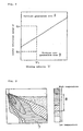
- Fig. 2 shows a vortices generation area A and a vortices non-generation area B in the case where a blowing velocity (wind velocity) of air flow ⁇ and a louver rotational speed ⁇ are changed.
- a blowing velocity wind velocity
- ⁇ 1 if the louver rotational speed is ⁇ 1 , large vortices are generated, and while the temperature diffusion in the louver rotational direction ⁇ increases, the reachability to the blowing direction R decreases.
- the rotational speed is set to a speed within the vortices non-generation area (area B in Fig. 2) relative to the wind velocity of blowing air flow, hence the downward reachability in the room can be secured enough.
- the louver rotational speed is set to a speed within the vortices generation area (area A in Fig. 2) relative to the wind velocity of blowing air flow, hence large vortices are generated backward of the louver rotational direction and the temperature diffusion in the louver rotational direction ⁇ is enhanced.
- an air conditioner which is able to form a room air state of higher comfortability, as compared with the prior art, in which, at the time of heating, both the downward reachability in the room and the uniformity of temperature stand together can be provided.
- another feature of the present invention is to employ following means; that is, the blowing velocity of air flow while the louver is moved rotationally below a predetermined blowing angle is set to a velocity within a vortices non-generation area relative to the louver rotational speed and the blowing velocity of air flow while the louver is moved rotationally above the predetermined blowing angle is set to a velocity within a vortices generation area relative to the louver rotational speed.
- the predetermined blowing angle can be set to an angle of 40° to 50° inclined downwardly from the horizontal direction.
- Fig. 7 shows a vortices generation area A and a vortices non-generation area B in the case where the blowing velocity (wind velocity) of air flow ⁇ and the louver rotational speed ⁇ are changed.
- the louver rotational speed is ⁇ 1
- the blowing velocity is ⁇ 1
- large vortices are generated, and while the temperature diffusion in the louver rotational direction ⁇ increases, the reachability to the blowing direction R decreases.
- the blowing velocity is ⁇ 2
- large vortices are not generated, and while the temperature diffusion in the louver rotational direction ⁇ becomes smaller, the reachability to the blowing direction R becomes larger.
- the blowing velocity of air flow ⁇ is set to a velocity within the vortices non-generation area (area B in Fig. 7) relative to the louver rotational speed ⁇ , hence the downward reachability in the room can be secured enough.
- the blowing velocity of air flow ⁇ is set to a velocity within the vortices generation area (area A in Fig. 7) relative to the louver rotational speed ⁇ , hence large vortices are generated backward of the louver rotational direction and the temperature diffusion in the louver rotational direction ⁇ is enhanced, and as a result thereof, a temperature field of broad comfort temperature area and good temperature uniformity is formed.
- an air conditioner which is able to form a room air state of higher comfortability, as compared with the prior art, in which, at the time of heating, both the downward reachability in the room and the uniformity of temperature stand together can be provided.
- a further feature of the present invention is to employ following means; that is, at the time of cooling, the rotational speed of louver while it is moved rotationally above a predetermined blowing angle is set to a speed within a vortices non-generation area relative to the wind velocity of blowing air flow or to a stationary state or to a state wherein said both cases of state are used by switching.
- the rotational speed of louver while it is moved rotationally below the predetermined blowing angle is set to a speed within a vortices generation area relative to the wind velocity of blowing air flow.
- Said predetermined blowing angle can be set to an angle of 25° to 40° inclined downwardly from the horizontal direction.
- FIG. 2 showing the vortices generation area A and the vortices non-generation area B in the case where the blowing velocity (wind velocity) of air flow ⁇ and the louver rotational speed w are changed, where the blowing velocity is ⁇ 1 , if the louver rotational speed is ⁇ 1 , large vortices are generated, and while the temperature diffusion in the louver rotational direction ⁇ increases, the reachability to the blowing direction R decreases.
- the louver rotational speed is set to a speed within the vortices non-generation area (area B in Fig. 2) relative to the wind velocity of blowing air flow, hence the reachability to the blowing direction R can be secured enough.
- the louver rotational speed is set to a speed within the vortices generation area (area A in Fig. 2) relative to the wind velocity of blowing air flow, hence large vortices are generated backward of the louver rotational direction and the temperature diffusion in the louver rotational direction ⁇ is enhanced.
- an air conditioner which is able to form a room air state of higher comfortability, as compared with the prior art, in which, at the time of cooling, both the horizontal frontward reachability in the room and the uniformity of temperature stand together can be provided.
- still another feature of the present invention is to employ following means; that is, at the time of cooling, the blowing velocity of air flow while the louver is moved rotationally above a predetermined blowing angle is set to a velocity within a vortices non-generation area relative to the louver rotational speed and the blowing velocity of air flow while the louver is moved rotationally below the predetermined blowing angle is set to a velocity within a vortices generation area relative to the louver rotational speed.
- Fig. 7 showing the vortices generation area A and the vortices non-generation area B in the case where the blowing velocity (wind velocity) of air flow ⁇ and the louver rotational speed ⁇ are changed, where the louver rotational speed is ⁇ 1 , if the blowing velocity is ⁇ 1 , large vortices are generated, and while the temperature diffusion in the louver rotational direction ⁇ increases, the reachability to the blowing direction R decreases. If the blowing velocity is ⁇ 2 , large vortices are not generated, and while the temperature diffusion in the louver rotational direction ⁇ becomes smaller, the reachability to the blowing direction R becomes larger.
- the blowing velocity of air flow ⁇ is set to a velocity within the vortices non-generation area (area B in Fig. 7) relative to the louver rotational speed ⁇ , hence the reachability to the horizontal frontward direction in the room can be secured enough.
- the blowing velocity of air flow ⁇ is set to a velocity within the vortices generation area (area A in Fig. 7) relative to the louver rotational speed ⁇ , hence large vortices are generated backward of the louver rotational direction and the temperature diffusion in the louver rotational direction ⁇ is enhanced, and as a result thereof, a temperature field of broad comfort temperature area and good temperature uniformity is formed.
- an air conditioner which is able to form a room air state of higher comfortability, as compared with the prior art, in which, at the time of cooling, both the horizontal frontward reachability in the room and the uniformity of temperature stand together can be provided.
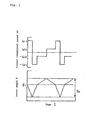
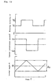
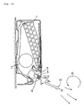
- an indoor unit of air conditioner of the construction shown in Fig. 14 comprises a stepping motor 4 for driving a louver 5 so as to make control shown in Fig. 1.
- a stepping motor 4 for driving a louver 5 so as to make control shown in Fig. 1.
- each portion of Fig. 14 is same as that described in the item "Description of the Prior Art" and repeated description is omitted.
- the rotational speed ⁇ of the louver 5 is set to a louver rotational speed ⁇ 2 within the vortices non-generation area B in Fig. 2 and while the louver 5 is moved rotationally above the predetermined blowing angle, that is, while the louver angle ⁇ in Fig. 1 is smaller than ⁇ 1 , the rotational speed ⁇ of the louver 5 is set to a louver rotational speed ⁇ 1 within the vortices generation area A in Fig. 2.
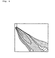
- Fig. 3 shows a room temperature distribution in said preferred embodiment according to the present invention
- Fig. 4 shows a room temperature distribution in an air conditioner in the prior art.
- the downward reachability 7 of blowing air flow in the room is good and the comfort temperature area 8 also is broad, as compared with the prior art.
- Fig. 5 shows a standard deviation of temperature non-uniformity at the position 60 cm above the room floor of this preferred embodiment and of an air conditioner in the prior art.
- a temperature distribution in which the standard deviation of temperature non-uniformity is small and the uniformity is good, as compared with the prior art, can be formed.
- the louver angle ⁇ 1 for changing the louver rotational speed to an angle of 40° to 50°, but in a case where one of them is to be given a preference or according to an installation position etc., the angle ⁇ 1 may be made changeable for adjustment corresponding thereto.
- an indoor unit of air conditioner of the construction shown in Fig. 14 comprises a variable speed motor 9 for driving a fan 2 so as to make control of the blowing velocity of air flow as shown in Fig. 6 at the time of heating.
- a damper 11 to be driven by a stepping motor 10, for adjusting the height of blowing passage, as shown in Fig. 8, may be used.
- each portion of Fig. 8 is same as that described in the item "Description of the Prior Art" and repeated description is omitted.
- the blowing velocity of air flow ⁇ is set to a velocity ⁇ 2 within the vortices non-generation area B in Fig. 7 and while the louver 5 is moved rotationally above the predetermined blowing angle, that is, while the louver angle ⁇ in Fig. 6 is smaller than ⁇ 1 , the blowing velocity of air flow ⁇ is set to a velocity ⁇ 1 within the vortices generation area A in Fig. 7.
- an indoor unit of air conditioner of the construction shown in Fig. 14 comprises a stepping motor 4 for driving a louver 5 so as to make control shown in Fig. 9 at the time of cooling.
- the rotational speed ⁇ of the louver 5 is set to a louver rotational speed ⁇ 2 within the vortices non-generation area B in Fig. 2 and to a stationary state during a certain time period, and while the louver 5 is moved rotationally below the predetermined blowing angle, that is, while the louver angle ⁇ in Fig. 9 is larger than ⁇ 1 , the rotational speed ⁇ of the louver 5 is set to a louver rotational speed ⁇ 1 within the vortices generation area A in Fig. 2.
- Fig. 10 shows a room temperature distribution in this preferred embodiment according to the present invention
- Fig. 11 shows a room temperature distribution in an air conditioner in the prior art.
- the frontward reachability 7 of the blowing air flow in the room is good and the comfort temperature area 8 also is broad, as compared with the prior art.
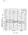
- Fig. 12 shows a standard deviation of temperature non-uniformity at the position 60 cm above the room floor of this preferred embodiment and of an air conditioner in the prior art.
- a temperature distribution in which the standard deviation of temperature non-uniformity is small and the uniformity is good, as compared with the prior art, can be formed.
- the louver angle ⁇ 1 for changing the louver rotational speed to an angle of 25° to 40°, but in a case where one of them is to be given a preference or according to an installation position etc., the angle ⁇ 1 may be made changeable for adjustment corresponding thereto.
- an indoor unit of air conditioner of the construction shown in Fig. 14 comprises a variable speed motor 9 for driving a fan 2 so as to make control of the blowing velocity of air flow as shown in Fig. 13 at the time of cooling.
- a damper 11 to be driven by a stepping motor 10, for adjusting the height of blowing passage, as shown in Fig. 8, may be used.
- the blowing velocity of air flow ⁇ is set to a velocity ⁇ 2 within the vortices non-generation area B in Fig. 7 and while the louver 5 is moved rotationally below the predetermined blowing angle, that is, while the louver angle ⁇ in Fig. 13 is larger than ⁇ 1 , the blowing velocity of air flow ⁇ is set to a velocity ⁇ 1 within the vortices generation area A in Fig. 7.
- An air conditioner according to the present invention having effect as follows; that is, at the time of heating, while the louver is moved rotationally below the predetermined blowing angle, the downward reachability in the room is good and especially the problem of cold feeling around feet is dissolved.
- the louver is moved rotationally above the predetermined blowing angle, the horizontal frontward reachability in the room is good. And at the time of cooling, while the louver is moved rotationally below the predetermined blowing angle, an air conditioning of high comfortableness in which the temperature diffusion is large, the comfort temperature area is broad and the temperature uniformity in the room space is good can be provided.
Landscapes
- Engineering & Computer Science (AREA)
- Chemical & Material Sciences (AREA)
- Combustion & Propulsion (AREA)
- Mechanical Engineering (AREA)
- General Engineering & Computer Science (AREA)
- Physics & Mathematics (AREA)
- Fluid Mechanics (AREA)
- Air Conditioning Control Device (AREA)
- Air-Flow Control Members (AREA)
Claims (4)
- Verfahren zum Steuern einer Klimaanlage, bei der eine Leitklappe (5) an einer Blasöffnung vorgesehen ist und die Leitklappe (5) durch einen Geschwindigkeitsregelmechanismus mittels Drehung von oben nach unten oder von unten nach oben bewegt werden kann,
wobei der Geschwindigkeitsregelmechanismus beim Heizen eine Drehgeschwindigkeit (ω) der Leitklappe (5), während die Leitklappe (5) unter einem ersten vorbestimmten Blaswinkel (1) durch Drehen bewegt wird, auf eine Geschwindigkeit (±ω2) innerhalb eines Nicht-Wirbelstromerzeugungsbereichs (B) relativ zu einer Geschwindigkeit (v) eines Blasluftstroms und, während die Leitklappe (5) über dem ersten vorbestimmten Blaswinkel (1) durch Drehen bewegt wird, auf eine Geschwindigkeit (±w1) innerhalb eines Wirbelstromerzeugungsbereichs (A) relativ zu der Geschwindigkeit (ν) des Luftblasstroms einstellt,
wobei der Geschwindigkeitsregelmechanismus die Drehgeschwindigkeit (w) der Leitklappe beim Kühlen, während die Leitklappe (5) über einem zweiten vorbestimmten Blaswinkel (2) durch Drehen bewegt wird, auf eine Geschwindigkeit (±ω2) innerhalb des Nicht-Wirbelstromerzeugungsbereichs (B) relativ zu einer Geschwindigkeit (ν) des Blasluftstroms oder auf einen stationären Zustand oder auf einen Zustand, bei dem beide Fälle von Zuständen eingesetzt werden, und, während die Leitklappe (5) unter dem zweiten vorbestimmten Blaswinkel (2) durch Drehen bewegt wird, auf eine Geschwindigkeit (±ω1) innerhalb des Wirbelstromerzeugungsbereichs (A) relativ zu der Strömungsgeschwindigkeit (ν), des Blasluftstroms einstellt, und
wobei |±ω2| < |±ω1| ist. - Verfahren zum Steuern einer Klimaanlage, bei der eine Leitklappe (5) an einer Blasöffnung vorgesehen ist und die Leitklappe (5) durch einen Geschwindigkeitsregelmechanismus mittels Drehung von oben nach unten oder von unten nach oben bewegt werden kann,
wobei eine Blasgeschwindigkeit (ν) von aus der Blasöffnung ausströmender Luft beim Heizen, während die Leitklappe (5) unter einem ersten vorbestimmten Blaswinkel (1) durch Drehen bewegt wird, auf eine Geschwindigkeit (ν2) innerhalb eines Nicht-Wirbelstromerzeugungsbereichs (B) relativ zu einer Drehgeschwindigkeit (ω) der Leitklappe (5) und, während die Leitklappe (5) über dem ersten vorbestimmten Blaswinkel (1) durch Drehen bewegt wird, auf eine Geschwindigkeit (ν1) innerhalb eines Wirbelstromerzeugungsbereichs (A) relativ zu der Drehgeschwindigkeit (ω) der Leitklappe (5) eingestellt wird,
wobei eine Blasgeschwindigkeit (ν) einer aus der Blasöffnung ausströmenden Luft beim Kühlen, während die Leitklappe (5) über einem zweiten vorbestimmten Blaswinkel (2) auf eine Geschwindigkeit (ν2) innerhalb des Nicht-Wirbelstromerzeugungsbereichs (B) relativ zu einer Drehgeschwindigkeit (ω) der Leitklappe (5) durch Drehen bewegt wird und, während die Leitklappe (5) unter dem zweiten vorbestimmten Blaswinkel (2) durch Drehen bewegt wird, auf eine Geschwindigkeit (ν1) innerhalb des Wirbelstromerzeugungsbereichs (A) relativ zu der Drehgeschwindigkeit (ω) der Leitklappe (5) eingestellt wird, und
wobei ν1 < ν2 ist. - Verfahren zum Steuern einer Klimaanlage nach Anspruch 1 oder 2, wobei der erste vorbestimmte Blaswinkel (1) auf einen Winkel von 40° bis 50° von der Horizontalrichtung nach unten geneigt eingestellt wird.
- Verfahren zum Steuern einer Klimaanlage nach Anspruch 1, 2 oder 3, wobei der zweite vorbestimmte Blaswinkel (2) auf einen Winkel von 25° bis 40° von der Horizontalrichtung nach unten geneigt eingestellt wird.
Applications Claiming Priority (3)
| Application Number | Priority Date | Filing Date | Title |
|---|---|---|---|
| JP7274140A JPH08233306A (ja) | 1994-12-27 | 1995-10-23 | 空気調和機 |
| JP274140/95 | 1995-10-23 | ||
| JP27414095 | 1995-10-23 |
Publications (3)
| Publication Number | Publication Date |
|---|---|
| EP0770829A2 EP0770829A2 (de) | 1997-05-02 |
| EP0770829A3 EP0770829A3 (de) | 2001-02-21 |
| EP0770829B1 true EP0770829B1 (de) | 2005-01-05 |
Family
ID=17537587
Family Applications (1)
| Application Number | Title | Priority Date | Filing Date |
|---|---|---|---|
| EP96115841A Expired - Lifetime EP0770829B1 (de) | 1995-10-23 | 1996-10-02 | Klimaanlage |
Country Status (4)
| Country | Link |
|---|---|
| US (1) | US5743103A (de) |
| EP (1) | EP0770829B1 (de) |
| CN (4) | CN1099555C (de) |
| DE (1) | DE69634148D1 (de) |
Families Citing this family (5)
| Publication number | Priority date | Publication date | Assignee | Title |
|---|---|---|---|---|
| US7294052B2 (en) * | 2004-08-02 | 2007-11-13 | Carrier Corporation | Control for dual stepper motors |
| KR100640801B1 (ko) * | 2005-05-10 | 2006-11-02 | 엘지전자 주식회사 | 천장형 에어컨의 베인 제어방법 |
| EP3086048B1 (de) * | 2013-12-19 | 2019-08-28 | Mitsubishi Electric Corporation | Klimaanlagenvorrichtung |
| CN105066334B (zh) * | 2015-07-23 | 2018-06-05 | 合肥美的暖通设备有限公司 | 空调器及其控制方法、控制装置 |
| CN111412607B (zh) * | 2020-03-31 | 2021-09-28 | 广东美的制冷设备有限公司 | 具有尾迹的涡环生成方法、装置、空调器及存储介质 |
Family Cites Families (11)
| Publication number | Priority date | Publication date | Assignee | Title |
|---|---|---|---|---|
| JPS6091152A (ja) * | 1983-10-26 | 1985-05-22 | Hitachi Ltd | ヒ−トポンプ式空気調和機 |
| JPS62276353A (ja) * | 1986-05-23 | 1987-12-01 | Toshiba Corp | 空気調和機のグリルスイング角制御装置 |
| JPH0792257B2 (ja) * | 1988-08-09 | 1995-10-09 | 株式会社東芝 | 空気調和装置 |
| JPH02287042A (ja) * | 1989-04-28 | 1990-11-27 | Mitsubishi Heavy Ind Ltd | 空気調和機の吹出ルーバの制御方法 |
| JP2516684B2 (ja) * | 1989-06-26 | 1996-07-24 | 三菱重工業株式会社 | 空気調和機のル―バ制御方法 |
| US5072878A (en) * | 1989-07-31 | 1991-12-17 | Mitsubishi Denki Kabushiki Kaisha | Air conditioning apparatus |
| JP2597012B2 (ja) * | 1989-09-11 | 1997-04-02 | 三菱重工業株式会社 | 空気調和機の風向変更装置 |
| JPH04230411A (ja) * | 1990-12-28 | 1992-08-19 | Mazda Motor Corp | 車両用空調装置 |
| JP3085737B2 (ja) * | 1991-07-17 | 2000-09-11 | ダイキン工業株式会社 | 空気調和機 |
| GB2260831B (en) * | 1991-10-18 | 1995-02-15 | Toshiba Kk | Air conditioning apparatus having louver for changing the direction of air into room |
| JPH05332606A (ja) * | 1992-06-02 | 1993-12-14 | Mitsubishi Heavy Ind Ltd | 空気調和機 |
-
1996
- 1996-09-27 US US08/722,832 patent/US5743103A/en not_active Expired - Lifetime
- 1996-10-02 EP EP96115841A patent/EP0770829B1/de not_active Expired - Lifetime
- 1996-10-02 DE DE69634148T patent/DE69634148D1/de not_active Expired - Lifetime
- 1996-10-21 CN CN96122847A patent/CN1099555C/zh not_active Expired - Lifetime
-
2002
- 2002-01-31 CN CNB021034052A patent/CN1172132C/zh not_active Expired - Fee Related
- 2002-01-31 CN CNB021034060A patent/CN1172133C/zh not_active Expired - Fee Related
- 2002-01-31 CN CNB021034044A patent/CN1172131C/zh not_active Expired - Fee Related
Also Published As
| Publication number | Publication date |
|---|---|
| DE69634148D1 (de) | 2005-02-10 |
| CN1099555C (zh) | 2003-01-22 |
| EP0770829A2 (de) | 1997-05-02 |
| CN1374488A (zh) | 2002-10-16 |
| CN1172131C (zh) | 2004-10-20 |
| CN1156234A (zh) | 1997-08-06 |
| US5743103A (en) | 1998-04-28 |
| CN1172133C (zh) | 2004-10-20 |
| CN1375666A (zh) | 2002-10-23 |
| CN1367350A (zh) | 2002-09-04 |
| CN1172132C (zh) | 2004-10-20 |
| EP0770829A3 (de) | 2001-02-21 |
Similar Documents
| Publication | Publication Date | Title |
|---|---|---|
| US5924923A (en) | Air conditioner indoor unit | |
| US4795089A (en) | Room air conditioner | |
| JP2011226727A (ja) | 空気調和機 | |
| JPH0792257B2 (ja) | 空気調和装置 | |
| JP3432022B2 (ja) | 空気調和機 | |
| EP0770829B1 (de) | Klimaanlage | |
| US4848214A (en) | Supply and return air plenum unit for duct air-conditioning systems | |
| US4890545A (en) | Air conditioner | |
| JP2001116327A (ja) | 空気調和機の風向制御方法 | |
| JP3358802B2 (ja) | 空気調節機 | |
| JP3300964B2 (ja) | Vav制御システム | |
| JP2003014287A (ja) | 空気調和装置の風向調整装置 | |
| JP2644837B2 (ja) | 天井埋込型空気調和機 | |
| JPH11245644A (ja) | 自動車用空調装置 | |
| JPH06123481A (ja) | 空気調和機の制御装置 | |
| JP2001153433A (ja) | 空気調和機の風向制御方法 | |
| JPH0532119A (ja) | 自動車用空調装置 | |
| JP2757734B2 (ja) | 空気調和機の制御方法 | |
| JPH08233306A (ja) | 空気調和機 | |
| KR19990004452A (ko) | 상하송풍방식의 히트펌프형 에어콘과 그 제어방법 | |
| JPH10110967A (ja) | 空気調和システム | |
| JPS61285339A (ja) | 空気調和機制御装置 | |
| JPH03160263A (ja) | 空気調和機の制御方法 | |
| JPH0434353Y2 (de) | ||
| JPH05215394A (ja) | 空気調和機 |
Legal Events
| Date | Code | Title | Description |
|---|---|---|---|
| PUAI | Public reference made under article 153(3) epc to a published international application that has entered the european phase |
Free format text: ORIGINAL CODE: 0009012 |
|
| 17P | Request for examination filed |
Effective date: 19961030 |
|
| AK | Designated contracting states |
Kind code of ref document: A2 Designated state(s): DE FR GB IT |
|
| PUAL | Search report despatched |
Free format text: ORIGINAL CODE: 0009013 |
|
| AK | Designated contracting states |
Kind code of ref document: A3 Designated state(s): DE FR GB IT |
|
| RIC1 | Information provided on ipc code assigned before grant |
Free format text: 7F 24F 11/00 A, 7F 24F 1/00 B |
|
| 17Q | First examination report despatched |
Effective date: 20030513 |
|
| GRAP | Despatch of communication of intention to grant a patent |
Free format text: ORIGINAL CODE: EPIDOSNIGR1 |
|
| GRAS | Grant fee paid |
Free format text: ORIGINAL CODE: EPIDOSNIGR3 |
|
| GRAA | (expected) grant |
Free format text: ORIGINAL CODE: 0009210 |
|
| AK | Designated contracting states |
Kind code of ref document: B1 Designated state(s): DE FR GB IT |
|
| PG25 | Lapsed in a contracting state [announced via postgrant information from national office to epo] |
Ref country code: FR Free format text: LAPSE BECAUSE OF NON-PAYMENT OF DUE FEES Effective date: 20050105 |
|
| REG | Reference to a national code |
Ref country code: GB Ref legal event code: FG4D |
|
| REF | Corresponds to: |
Ref document number: 69634148 Country of ref document: DE Date of ref document: 20050210 Kind code of ref document: P |
|
| PG25 | Lapsed in a contracting state [announced via postgrant information from national office to epo] |
Ref country code: DE Free format text: LAPSE BECAUSE OF FAILURE TO SUBMIT A TRANSLATION OF THE DESCRIPTION OR TO PAY THE FEE WITHIN THE PRESCRIBED TIME-LIMIT Effective date: 20050406 |
|
| PG25 | Lapsed in a contracting state [announced via postgrant information from national office to epo] |
Ref country code: IT Free format text: LAPSE BECAUSE OF NON-PAYMENT OF DUE FEES Effective date: 20051002 Ref country code: GB Free format text: LAPSE BECAUSE OF NON-PAYMENT OF DUE FEES Effective date: 20051002 |
|
| PLBE | No opposition filed within time limit |
Free format text: ORIGINAL CODE: 0009261 |
|
| STAA | Information on the status of an ep patent application or granted ep patent |
Free format text: STATUS: NO OPPOSITION FILED WITHIN TIME LIMIT |
|
| 26N | No opposition filed |
Effective date: 20051006 |
|
| REG | Reference to a national code |
Ref country code: GB Ref legal event code: FG4D |
|
| EN | Fr: translation not filed | ||
| GBPC | Gb: european patent ceased through non-payment of renewal fee |
Effective date: 20051002 |