EP0770948A1 - Dispositif de conditionnement d'air - Google Patents
Dispositif de conditionnement d'air Download PDFInfo
- Publication number
- EP0770948A1 EP0770948A1 EP96116948A EP96116948A EP0770948A1 EP 0770948 A1 EP0770948 A1 EP 0770948A1 EP 96116948 A EP96116948 A EP 96116948A EP 96116948 A EP96116948 A EP 96116948A EP 0770948 A1 EP0770948 A1 EP 0770948A1
- Authority
- EP
- European Patent Office
- Prior art keywords
- compressor
- air conditioner
- reference numeral
- temperature
- temperature sensor
- Prior art date
- Legal status (The legal status is an assumption and is not a legal conclusion. Google has not performed a legal analysis and makes no representation as to the accuracy of the status listed.)
- Granted
Links
- 238000004378 air conditioning Methods 0.000 claims description 8
- 238000001816 cooling Methods 0.000 description 16
- 239000003507 refrigerant Substances 0.000 description 10
- 238000010586 diagram Methods 0.000 description 6
- 238000010438 heat treatment Methods 0.000 description 4
- 239000003990 capacitor Substances 0.000 description 3
- 238000005192 partition Methods 0.000 description 2
- 230000000694 effects Effects 0.000 description 1
- 239000012535 impurity Substances 0.000 description 1
- 239000004065 semiconductor Substances 0.000 description 1
- 238000000638 solvent extraction Methods 0.000 description 1
- 238000010257 thawing Methods 0.000 description 1
Images


Classifications
-
- F—MECHANICAL ENGINEERING; LIGHTING; HEATING; WEAPONS; BLASTING
- F24—HEATING; RANGES; VENTILATING
- F24F—AIR-CONDITIONING; AIR-HUMIDIFICATION; VENTILATION; USE OF AIR CURRENTS FOR SCREENING
- F24F11/00—Control or safety arrangements
- F24F11/30—Control or safety arrangements for purposes related to the operation of the system, e.g. for safety or monitoring
-
- F—MECHANICAL ENGINEERING; LIGHTING; HEATING; WEAPONS; BLASTING
- F24—HEATING; RANGES; VENTILATING
- F24F—AIR-CONDITIONING; AIR-HUMIDIFICATION; VENTILATION; USE OF AIR CURRENTS FOR SCREENING
- F24F11/00—Control or safety arrangements
- F24F11/50—Control or safety arrangements characterised by user interfaces or communication
- F24F11/52—Indication arrangements, e.g. displays
-
- F—MECHANICAL ENGINEERING; LIGHTING; HEATING; WEAPONS; BLASTING
- F24—HEATING; RANGES; VENTILATING
- F24F—AIR-CONDITIONING; AIR-HUMIDIFICATION; VENTILATION; USE OF AIR CURRENTS FOR SCREENING
- F24F11/00—Control or safety arrangements
- F24F11/50—Control or safety arrangements characterised by user interfaces or communication
- F24F11/56—Remote control
-
- F—MECHANICAL ENGINEERING; LIGHTING; HEATING; WEAPONS; BLASTING
- F24—HEATING; RANGES; VENTILATING
- F24F—AIR-CONDITIONING; AIR-HUMIDIFICATION; VENTILATION; USE OF AIR CURRENTS FOR SCREENING
- F24F11/00—Control or safety arrangements
- F24F11/62—Control or safety arrangements characterised by the type of control or by internal processing, e.g. using fuzzy logic, adaptive control or estimation of values
- F24F11/63—Electronic processing
-
- F—MECHANICAL ENGINEERING; LIGHTING; HEATING; WEAPONS; BLASTING
- F24—HEATING; RANGES; VENTILATING
- F24F—AIR-CONDITIONING; AIR-HUMIDIFICATION; VENTILATION; USE OF AIR CURRENTS FOR SCREENING
- F24F11/00—Control or safety arrangements
- F24F11/70—Control systems characterised by their outputs; Constructional details thereof
- F24F11/72—Control systems characterised by their outputs; Constructional details thereof for controlling the supply of treated air, e.g. its pressure
- F24F11/74—Control systems characterised by their outputs; Constructional details thereof for controlling the supply of treated air, e.g. its pressure for controlling air flow rate or air velocity
-
- F—MECHANICAL ENGINEERING; LIGHTING; HEATING; WEAPONS; BLASTING
- F24—HEATING; RANGES; VENTILATING
- F24F—AIR-CONDITIONING; AIR-HUMIDIFICATION; VENTILATION; USE OF AIR CURRENTS FOR SCREENING
- F24F11/00—Control or safety arrangements
- F24F11/70—Control systems characterised by their outputs; Constructional details thereof
- F24F11/80—Control systems characterised by their outputs; Constructional details thereof for controlling the temperature of the supplied air
- F24F11/86—Control systems characterised by their outputs; Constructional details thereof for controlling the temperature of the supplied air by controlling compressors within refrigeration or heat pump circuits
-
- F—MECHANICAL ENGINEERING; LIGHTING; HEATING; WEAPONS; BLASTING
- F24—HEATING; RANGES; VENTILATING
- F24F—AIR-CONDITIONING; AIR-HUMIDIFICATION; VENTILATION; USE OF AIR CURRENTS FOR SCREENING
- F24F11/00—Control or safety arrangements
- F24F11/88—Electrical aspects, e.g. circuits
-
- F—MECHANICAL ENGINEERING; LIGHTING; HEATING; WEAPONS; BLASTING
- F04—POSITIVE - DISPLACEMENT MACHINES FOR LIQUIDS; PUMPS FOR LIQUIDS OR ELASTIC FLUIDS
- F04B—POSITIVE-DISPLACEMENT MACHINES FOR LIQUIDS; PUMPS
- F04B2203/00—Motor parameters
- F04B2203/02—Motor parameters of rotating electric motors
- F04B2203/0205—Temperature
-
- F—MECHANICAL ENGINEERING; LIGHTING; HEATING; WEAPONS; BLASTING
- F04—POSITIVE - DISPLACEMENT MACHINES FOR LIQUIDS; PUMPS FOR LIQUIDS OR ELASTIC FLUIDS
- F04C—ROTARY-PISTON, OR OSCILLATING-PISTON, POSITIVE-DISPLACEMENT MACHINES FOR LIQUIDS; ROTARY-PISTON, OR OSCILLATING-PISTON, POSITIVE-DISPLACEMENT PUMPS
- F04C2270/00—Control; Monitoring or safety arrangements
- F04C2270/90—Remote control, e.g. wireless, via LAN, by radio, or by a wired connection from a central computer
-
- F—MECHANICAL ENGINEERING; LIGHTING; HEATING; WEAPONS; BLASTING
- F24—HEATING; RANGES; VENTILATING
- F24F—AIR-CONDITIONING; AIR-HUMIDIFICATION; VENTILATION; USE OF AIR CURRENTS FOR SCREENING
- F24F2110/00—Control inputs relating to air properties
- F24F2110/10—Temperature
-
- F—MECHANICAL ENGINEERING; LIGHTING; HEATING; WEAPONS; BLASTING
- F25—REFRIGERATION OR COOLING; COMBINED HEATING AND REFRIGERATION SYSTEMS; HEAT PUMP SYSTEMS; MANUFACTURE OR STORAGE OF ICE; LIQUEFACTION SOLIDIFICATION OF GASES
- F25B—REFRIGERATION MACHINES, PLANTS OR SYSTEMS; COMBINED HEATING AND REFRIGERATION SYSTEMS; HEAT PUMP SYSTEMS
- F25B2500/00—Problems to be solved
- F25B2500/29—High ambient temperatures
Definitions
- the present invention relates to an air conditioner having controller equipped with electrical parts such as a power transistor, etc., the controller controlling a driving current of a compressor, etc.
- a controller used in this type of air conditioner is generally equipped with a power transistor as an electrical part for control.
- the upper-limit value of the driving current of the compressor is suddenly reduced to a predetermined fixed value or less on the basis of the detected temperature of a detector for detecting the outside air temperature to protect the electrical parts such as the power transistor, etc., from heat.
- a thermostat is mounted on a heat sink for cooling the power transistor, and the driving of the compressor is stopped when the thermostat detects a predetermined temperature. having the outside temperature detector, the control mode for the protection of the electrical parts is greatly varied between a situation where an outdoor unit having an outside air temperature detector is located under a sunny condition and a situation where it is located under an unsunny or shady condition.
- an indoor unit is often located in a room having a sunny aspect.
- the cooling operation trends to be more frequently carried out as compared with such a situation that the indoor unit is located in a room with an unsunny aspect. Therefore, for example, in such a severely hot condition that the outside air temperature is very high, the reduction of the driving current of the compressor by the protection control and the stop control of the driving operation are more frequently performed. Therefore, it is very difficult to protect the power relay in accordance with the outside air temperature.
- the stop control of the driving of the compressor trends to be more frequently performed by the protection control. This situation occurs in a case where the cooling operation is particularly required by a user. Therefore, the control of stopping the driving of the compressor greatly disturbs the user, who is prevented from enjoying a comfortable air-conditioning atmosphere, and it would be preferable to continue the driving of the compressor although the driving power of the compressor is a little lowered.
- An object of the present invention is to provide an air conditioner which is enabled to be continuously operated even when the driving operation thereof is carried out under an overload.
- an air conditioner which has a controller equipped with heat-producing electrical parts and in which the driving current of a compressor, etc., is controlled by the controller, which includes a temperature sensor which is provided to or in the vicinity of at least one heat-sensitive electrical part of the electrical parts and adapted to detect the temperature of the heat-sensitive electrical part, and means for gradually reducing the upper-limit value of the driving current of the compressor when the temperature detected by the temperature sensor is higher than a predetermined value.
- the controller is equipped with a power transistor, and a temperature sensor is provided to the transistor or in the vicinity of the transistor.
- the means reduces the upper-limit value of the driving current of the compressor.
- the means reduces the upper-limit value of the driving current of the compressor stepwise or linearly in accordance with an increase of the temperature detected by the temperature sensor.
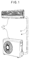
- Fig. 1 is a diagram showing the outlook of the air conditioner 1, and the outline of Fig. 1 is different from the actual arrangement of the air conditioner because both the front face sides of the outdoor and indoor units of the air conditioner are illustrated as being faced to the same direction.
- the air conditioner 1 shown in Fig. 1 is mainly constructed of an indoor unit 2 and an outdoor unit 3, and both the units are connected to each other through an interunit pipe 4 and an interunit cable 5.
- reference numeral 10 represents a refrigerant circuit of the air conditioner 1
- reference numeral 11 represents a compressor for compressing the refrigerant
- reference numeral 12 represents a muffler
- reference numeral 13 represents a four-way valve for changing the direction of the refrigerant flow
- reference numeral 14 represents an outdoor heat exchanger
- reference numeral 15 represents an expansion device (pressure-reducing device) using capillary tubes
- reference numeral 16 represents a strainer for removing impurities from the refrigerant
- reference numeral 17 represents a service valve
- reference numeral 4A represents an interunit pipe
- reference numeral 18 represents an auxiliary pipe
- reference numeral 19 represents an indoor heat exchanger
- reference numeral 20 represents an auxiliary pipe
- reference numeral 4B represents an interunit pipe
- reference 21 represents a service valve
- reference numeral 22 represents a muffler
- reference numeral 23 represents an accumulator
- reference numerals 24A to 24G represent refrigerant pipes for connecting the respective equipments as
- an arrow indicated by a solid line represents the refrigerant flow in cooling operation (under defrosting operation) and an arrow indicated by a dotted line represents the refrigerant flow in heating operation.
- the cooling and heating operation of the air conditioner is substantially similar to that of the conventional air conditioner, and thus the detailed description thereof is omitted from the specification.
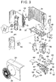
- Fig. 3 is an exploded view showing an outdoor unit of the air conditioner shown in Fig. 1.
- reference numeral 30 represents a panel comprising a top plate and a front plate which are integrally formed with each other
- reference numeral 31 represents a panel comprising both side plates and a back plate which are integrally formed with each other
- reference numeral 32 represents a bottom plate.
- the panel 30, the panel 31 and the bottom plate 32 constitute an outer case 33.
- Reference numeral 34 represents a drain pipe
- reference numeral 35 represents a fan guard.
- Reference numeral 36 represents a propeller fan
- reference numeral 37 represents a fan motor for driving the fan 36
- reference numeral 38 represents a motor stand for supporting the motor 37
- reference numeral 39 represents an outside air temperature detector (sensor) for detecting the outside air temperature
- reference numeral 40 represents an outdoor heat exchanger detector (sensor) for detecting the temperature of the outdoor heat exchanger
- reference numeral 41 represents a vibration preventing rubber member for suppressing the vibration of the compressor
- reference numeral 42 represents a cover for covering a terminal stand and wires
- reference numeral 43 represents a valve cover
- reference numeral 44 represents a partition plate for partitioning a heat exchanger chamber and a mechanical chamber from each other
- reference numeral 45 represents a reactor mounted to the partition plate 44
- reference numeral 13A represents an electromagnetic coil for driving a needle of the four-way valve 13
- reference numeral 46 represents a detector for detecting the temperature of the refrigerant
- reference numeral 47 represents an electrical equipment box
- reference numeral 48 represents a cover for the
- Fig. 4 shows an electrical circuit diagram 1A of the air conditioner, and it mainly comprises an electrical circuit 2A at the indoor unit side and an electrical circuit 3A at the outdoor unit side.
- Reference numeral 61 represents a plug for supplying power to the controller of the indoor unit
- reference numeral 62 represents a switch for the power source
- reference numeral 63 represents a power relay
- reference numeral 64 represents a power relay board.
- a power relay 65 and a fuse 66 are provided on the power relay board 64.
- Reference numeral 67 represents a power source board
- reference numeral 68 represents a power source for the motor
- reference numeral 69 represents a serial power source
- reference numeral 70 represents a power source for a control circuit
- reference numeral 71 represents a driving circuit
- reference numeral 72 represents a fuse
- reference numeral 73 represents a fan motor
- reference numeral 74 represents a control board
- reference numeral 75 represents a serial circuit
- reference numeral 76 represents a driving circuit
- reference numeral 77 represents a microcomputer (which is abbreviated as "micron")
- reference numeral 78 represents a service LED (light emitting diode) used for service
- reference numeral 79 represents a driving change-over switch
- reference numeral 80 represents an up-and-down flap motor for driving an up-and-down flap (an air blow direction changing plate which is located to extend in a lateral direction and adapted to change the direction of the air flow (upward and downward directions)
- reference numeral 81 represents
- Reference numeral 84 represents a room temperature sensor for detecting the temperature of the room air
- reference numeral 85 represents a heat exchange temperature sensor for detecting the temperature of the indoor heat exchanger
- reference numeral 86 represents a 3-pin terminal board at the indoor unit side
- reference numerals 5A,5B,and 5C represent interunit cables.
- Reference numeral 87 represents a control board
- reference numeral 88 represents a noise filter
- reference numeral 89 represents a serial circuit
- reference numeral 90 represents a noise filter
- reference numeral 91 represents a fuse
- reference numeral 92 represents a fuse
- reference numeral 93 represents a noise filter
- reference numeral 94 represents a switching power source
- reference numeral 95 represents a microcomputer.
- Reference numeral 96 represents a diode
- reference numeral 56A represents a power transistor which is provided in the HIC. The power transistor is connected to a drive circuit (not shown) for driving the transistor.
- Reference numeral 97 represents a temperature sensing element (temperature sensor) which is provided to the power transistor to detect the temperature of the power transistor.
- the temperature sensing element (temperature sensor) 97 is formed of a thermistor and serves to output a signal representing the detected temperature to the microcomputer 95.
- Reference numeral 37A represents a capacitor for the fan motor.
- the driving current of the compressor can be controlled by adjusting the driving frequency of the compressor under control of the control board. Accordingly, not only the driving power of the compressor can be varied, but also the driving current of the compressor can be varied under control of the control board (controller).
- the microcomputer receives signals from various sensors, and controls the driving frequency of the compressor to control the driving (rotational speed) of the compressor.
- the driving of the compressor is carried out at a driving level which is relatively near to the maximum level.
- the temperature of the HIC is liable to rises up to a relatively-high temperature.
- the temperature of the HIC is required to be set to 70°C or less.
- the driving of the air conditioner is controlled to be carried out as continuously as possible even if the driving power (cooling power) thereof is lowered.
- the driving of the compressor under such a situation is carried out as follows. It is assumed that the upper limit value of the driving current of the compressor is normally set to 15A. In this case, if the temperature detected by the temperature sensor is equal to a predetermined value (for example, :80°C), the driving frequency is controlled so that the upper limit value of the driving current of the compressor is reduced by 0.5A and thus it is set to 14.5A, for example. Therefore, the maximum value (upper limit value) of the cooling power is reduced, Nonetheless, the cooling operation continues, and the cooling operation avoids being suddenly stopped. Furthermore, when the detected temperature rises to 81°C, the upper limit value is further reduced by 0.5A, and thus the driving current is set to 14.0A, for example.
- a predetermined value for example, :80°C
- the upper limit value of the cooling operation is further successively reduced by every 0.5A and set to 13.5A, 13.0A, 12.5A, 12.0A,11.5A, 11.0A,10.5A, 10.0A respectively.
- the driving of the air conditioner is finally stopped to prevent the power transistor from being damaged (see Fig. 5).
- the predetermined value is set in the range of 80°C to 89°C, and it is varied every one degree.
- the value may be set in a broader range, and be varied by smaller or larger increments.
- the driving current of the compressor is varied by every 0.5A, however, it may be varied by every smaller or larger value.
- the temperature sensor is provided to (mounted on or built in) the power transistor or in the vicinity of the power transistor, and the upper limit value of the driving current of the compressor is reduced (particularly, gradually) when the temperature of the power transistor is higher than a predetermined value.
- the upper limit value of the driving current of the compressor is reduced in accordance with the increase of the temperature detected by the detector. Therefore, although the driving power of the compressor is lowered, excessive heating of the power transistor and other electrical parts in the vicinity of the power transistor can be prevented by the reduction of the driving power, so that stopping of the driving operation of the compressor due to the protection control can be reduced as much as possible. Therefore, unlike the conventional air conditioner in which the compressor is suddenly stopped, the present compressor is prevented from being suddenly stopped, and thus the present invention can provide a relatively comfortable air-conditioning atmosphere to the user.
- the upper limit value of the driving current of the compressor is gradually reduced in accordance with the temperature of the temperature sensor. Accordingly, when the temperature detected by the temperature sensor is relatively low, the reduction level of the upper limit value of the driving current is set to a small level. On the other hand, when the temperature detected by the temperature sensor is relatively high, the reduction level of the upper limit value of the driving current is set to a large level. That is, the upper limit value of the driving current of the compressor can be controlled so that the driving operation of the air conditioner is carried out as continuously as possible without being ceased. Therefore, the user hardly feels uncomfortable because the driving operation of the air conditioner is carried out continuously although the driving power is somewhat reduced (the cooling effect is less, as compared with a case where the air conditioning operation is completely ceased due to the stop of the driving operation.
- Fig. 6 is a graph showing a different control characteristic of the above-described controller.
- the difference between the control characteristics of Figs. 5 and 6 resides in that the control operation of Fig. 6 is carried out linearly, whereas the control operation of Fig. 5 is performed stepwise.
- the slope of the current value where the temperature of the power transistor is equal to 80° to 90°C, is equal to -0.5A/°C
- the driving power of the compressor can be reduced more smoothly when it is driven at the maximum power.
- the comfortable air conditioning level is suddenly lowered due to rapid reduction in cooling power.
- the power transistor is provided with the temperature sensor.
- the temperature sensor may be provided to another electrical part which is sensitive to heat (for example, the semiconductor parts, the ICs 53, 54, the electrolytic transistor 50, etc. on the board 49) to reduce the upper limit value of the driving current of the compressor.
- the temperature sensor may be disposed in the vicinity of the power transistor, or in a cooler to indirectly detect the temperature of the power transistor. In this case, the correlation between the temperature of the cooler and the temperature of the power transistor must be examined in advance to preset a predetermined value of the cooler.
- a power transistor in which a temperature sensor is beforehand built may be manufactured and used.
- a temperature sensor is provided to or in the vicinity of a heat-sensitive electrical part such as a power transistor or the like, and when the temperature detected by the temperature sensor is high, the upper limit value of the driving current of the compressor is reduced. Therefore, although the driving power of the air conditioner is lowered, the heating of the electrical parts such as the power transistor, etc., can be reduced due to the reduction of the driving power, so that sudden stopping of the driving operation of the air conditioner by the protection control is avoided as much as possible. Accordingly, as compared with the conventional air conditioner in which the driving of the compressor is relatively often stopped by the protection control, the present invention can provide an air condition which make users less uncomfortable.
- the present invention can provide an air conditioner which can prevent the heat-sensitive electrical parts such as the power transistor, etc., from being damaged and make users less uncomfortable as compared with the conventional air conditioner in which the driving of the compressor is relatively often stopped by the protection control.
- the upper limit value of the driving current of the compressor is reduced in accordance with the temperature detected by the temperature sensor. Therefore, when the temperature detected by the temperature sensor is relatively low, the reduction level of the upper limit value of the driving current is set to a smaller value. On the other hand, when the temperature detected by the temperature sensor is relatively high, the reduction level of the upper limit value of the driving current is set to a larger value. That is, the upper limit value of the driving current of the compressor is gradually controlled so that the driving of the compressor is carried out as continuously as possible without being ceased. Therefore, there is provided an air conditioner which prevents reduction in cooling power from occurring suddenly and thus makes users uncomfortable as little as possible.
Landscapes
- Engineering & Computer Science (AREA)
- General Engineering & Computer Science (AREA)
- Chemical & Material Sciences (AREA)
- Combustion & Propulsion (AREA)
- Mechanical Engineering (AREA)
- Physics & Mathematics (AREA)
- Signal Processing (AREA)
- Human Computer Interaction (AREA)
- Fluid Mechanics (AREA)
- Thermal Sciences (AREA)
- Fuzzy Systems (AREA)
- Mathematical Physics (AREA)
- Air Conditioning Control Device (AREA)
Applications Claiming Priority (3)
| Application Number | Priority Date | Filing Date | Title |
|---|---|---|---|
| JP7274223A JPH09113003A (ja) | 1995-10-23 | 1995-10-23 | 空気調和機 |
| JP274223/95 | 1995-10-23 | ||
| JP27422395 | 1995-10-23 |
Publications (2)
| Publication Number | Publication Date |
|---|---|
| EP0770948A1 true EP0770948A1 (fr) | 1997-05-02 |
| EP0770948B1 EP0770948B1 (fr) | 2001-09-05 |
Family
ID=17538745
Family Applications (1)
| Application Number | Title | Priority Date | Filing Date |
|---|---|---|---|
| EP96116948A Expired - Lifetime EP0770948B1 (fr) | 1995-10-23 | 1996-10-22 | Dispositif de conditionnement d'air |
Country Status (8)
| Country | Link |
|---|---|
| US (1) | US5764011A (fr) |
| EP (1) | EP0770948B1 (fr) |
| JP (1) | JPH09113003A (fr) |
| BR (1) | BR9605211A (fr) |
| CA (1) | CA2188523C (fr) |
| DE (1) | DE69614962T2 (fr) |
| MY (1) | MY112342A (fr) |
| SG (1) | SG55238A1 (fr) |
Cited By (1)
| Publication number | Priority date | Publication date | Assignee | Title |
|---|---|---|---|---|
| EP1482257A3 (fr) * | 2003-05-30 | 2005-02-16 | Sanyo Electric Co., Ltd. | Dispositif de refroidissement |
Families Citing this family (15)
| Publication number | Priority date | Publication date | Assignee | Title |
|---|---|---|---|---|
| JP4782941B2 (ja) * | 2001-05-16 | 2011-09-28 | サンデン株式会社 | 車両用空気調和装置 |
| JP4286064B2 (ja) * | 2003-05-30 | 2009-06-24 | 三洋電機株式会社 | 冷却装置 |
| KR100688169B1 (ko) * | 2004-12-28 | 2007-03-02 | 엘지전자 주식회사 | 에어컨의 냉방 과부하 운전 제어 방법 |
| US20080041081A1 (en) * | 2006-08-15 | 2008-02-21 | Bristol Compressors, Inc. | System and method for compressor capacity modulation in a heat pump |
| US8904814B2 (en) * | 2008-06-29 | 2014-12-09 | Bristol Compressors, International Inc. | System and method for detecting a fault condition in a compressor |
| US8601828B2 (en) * | 2009-04-29 | 2013-12-10 | Bristol Compressors International, Inc. | Capacity control systems and methods for a compressor |
| WO2013001829A1 (fr) * | 2011-06-29 | 2013-01-03 | パナソニック株式会社 | Dispositif de refroidissement et climatiseur comprenant celui-ci |
| US8845301B2 (en) * | 2011-06-29 | 2014-09-30 | Ford Global Technologies, Llc | Compressor control method |
| KR101481314B1 (ko) | 2013-09-04 | 2015-01-09 | 현대자동차주식회사 | 전동식 에어컨 컴프레서 제어기의 온도 제어방법 |
| CN103954022A (zh) * | 2014-04-09 | 2014-07-30 | 美的集团股份有限公司 | 温度检测保护装置和空调器 |
| JP6323221B2 (ja) * | 2014-07-08 | 2018-05-16 | 株式会社豊田自動織機 | モータ制御装置 |
| US11607928B2 (en) | 2017-03-10 | 2023-03-21 | Mobile Climate Control, Corp. | Method and apparatus for cooling an air conditioning system controller |
| US11037376B2 (en) * | 2017-03-28 | 2021-06-15 | Uop Llc | Sensor location for rotating equipment in a petrochemical plant or refinery |
| JP7112027B2 (ja) * | 2018-11-16 | 2022-08-03 | 三菱電機株式会社 | 空気調和機の室外機 |
| CN112197408B (zh) * | 2020-10-13 | 2022-04-01 | 广东美的制冷设备有限公司 | 压缩机绕组的加热控制方法、空调控制方法、系统和设备 |
Citations (9)
| Publication number | Priority date | Publication date | Assignee | Title |
|---|---|---|---|---|
| US4408244A (en) * | 1978-06-08 | 1983-10-04 | Suddeutsche Kuhlerfabrik Julius Fr. Behr Gmbh & Co. Kg | Circuit safe against overload for varying the amount of power to an electric blower motor |
| US4831836A (en) * | 1987-04-22 | 1989-05-23 | Mitsubishi Denki Kabushiki Kaisha | Frequency control apparatus of a multi-refrigeration cycle system |
| JPH025981A (ja) | 1988-06-27 | 1990-01-10 | Satoshi Takigawa | ゴルフ用テイ |
| US5095715A (en) * | 1990-09-20 | 1992-03-17 | Electric Power Research Institute, Inc. | Electric power demand limit for variable speed heat pumps and integrated water heating heat pumps |
| JPH0515185A (ja) * | 1991-07-02 | 1993-01-22 | Hitachi Ltd | 電動機の駆動装置 |
| JPH05203234A (ja) * | 1992-01-24 | 1993-08-10 | Matsushita Electric Ind Co Ltd | 空気調和機のパワートランジスタ保護装置 |
| EP0588633A1 (fr) * | 1992-09-18 | 1994-03-23 | Sanyo Electric Co., Ltd. | Appareil pour contrôler la température |
| JPH06233589A (ja) * | 1993-01-29 | 1994-08-19 | Hitachi Ltd | 回転数制御式空気調和機 |
| JPH07266852A (ja) * | 1994-03-31 | 1995-10-17 | Nippon Climate Syst:Kk | 電気自動車用空調装置 |
Family Cites Families (13)
| Publication number | Priority date | Publication date | Assignee | Title |
|---|---|---|---|---|
| JPS6025981A (ja) * | 1983-07-22 | 1985-02-08 | Tanabe Seiyaku Co Ltd | ベンゾチアゼピン誘導体及びその製法 |
| JPH0683590B2 (ja) * | 1984-07-04 | 1994-10-19 | 株式会社東芝 | 空気調和機 |
| JPS62178832A (ja) * | 1986-02-03 | 1987-08-05 | Hitachi Ltd | インバ−タ付空気調和機の制御回路 |
| US4667480A (en) * | 1986-09-22 | 1987-05-26 | General Electric Company | Method and apparatus for controlling an electrically driven automotive air conditioner |
| US5123080A (en) * | 1987-03-20 | 1992-06-16 | Ranco Incorporated Of Delaware | Compressor drive system |
| US5372015A (en) * | 1991-07-05 | 1994-12-13 | Kabushiki Kaisha Toshiba | Air conditioner controller |
| JPH0599484A (ja) * | 1991-07-12 | 1993-04-20 | Mitsubishi Electric Corp | 空気調和機の運転制御装置 |
| TW200560B (en) * | 1992-03-13 | 1993-02-21 | Sanyo Electric Machinery Co Ltd | Air conditioner controlling device |
| JPH06337153A (ja) * | 1993-05-28 | 1994-12-06 | Toshiba Corp | 空気調和機 |
| EP0652634B1 (fr) * | 1993-11-09 | 1999-01-07 | Sanyo Electric Co., Ltd. | Appareil de conditionnement utilisable pour une source de tension à large gamme |
| JP3404150B2 (ja) * | 1994-09-28 | 2003-05-06 | 東芝キヤリア株式会社 | 空気調和機及びその制御方法 |
| JPH08105644A (ja) * | 1994-10-05 | 1996-04-23 | Sanyo Electric Co Ltd | 空気調和機 |
| US5628201A (en) * | 1995-04-03 | 1997-05-13 | Copeland Corporation | Heating and cooling system with variable capacity compressor |
-
1995
- 1995-10-23 JP JP7274223A patent/JPH09113003A/ja active Pending
-
1996
- 1996-10-19 MY MYPI96004356A patent/MY112342A/en unknown
- 1996-10-22 US US08/735,087 patent/US5764011A/en not_active Expired - Fee Related
- 1996-10-22 SG SG1996010892A patent/SG55238A1/en unknown
- 1996-10-22 CA CA002188523A patent/CA2188523C/fr not_active Expired - Fee Related
- 1996-10-22 EP EP96116948A patent/EP0770948B1/fr not_active Expired - Lifetime
- 1996-10-22 DE DE69614962T patent/DE69614962T2/de not_active Expired - Fee Related
- 1996-10-23 BR BR9605211A patent/BR9605211A/pt not_active Application Discontinuation
Patent Citations (9)
| Publication number | Priority date | Publication date | Assignee | Title |
|---|---|---|---|---|
| US4408244A (en) * | 1978-06-08 | 1983-10-04 | Suddeutsche Kuhlerfabrik Julius Fr. Behr Gmbh & Co. Kg | Circuit safe against overload for varying the amount of power to an electric blower motor |
| US4831836A (en) * | 1987-04-22 | 1989-05-23 | Mitsubishi Denki Kabushiki Kaisha | Frequency control apparatus of a multi-refrigeration cycle system |
| JPH025981A (ja) | 1988-06-27 | 1990-01-10 | Satoshi Takigawa | ゴルフ用テイ |
| US5095715A (en) * | 1990-09-20 | 1992-03-17 | Electric Power Research Institute, Inc. | Electric power demand limit for variable speed heat pumps and integrated water heating heat pumps |
| JPH0515185A (ja) * | 1991-07-02 | 1993-01-22 | Hitachi Ltd | 電動機の駆動装置 |
| JPH05203234A (ja) * | 1992-01-24 | 1993-08-10 | Matsushita Electric Ind Co Ltd | 空気調和機のパワートランジスタ保護装置 |
| EP0588633A1 (fr) * | 1992-09-18 | 1994-03-23 | Sanyo Electric Co., Ltd. | Appareil pour contrôler la température |
| JPH06233589A (ja) * | 1993-01-29 | 1994-08-19 | Hitachi Ltd | 回転数制御式空気調和機 |
| JPH07266852A (ja) * | 1994-03-31 | 1995-10-17 | Nippon Climate Syst:Kk | 電気自動車用空調装置 |
Non-Patent Citations (4)
| Title |
|---|
| PATENT ABSTRACTS OF JAPAN vol. 017, no. 289 (E - 1375) 3 June 1993 (1993-06-03) * |
| PATENT ABSTRACTS OF JAPAN vol. 017, no. 645 (M - 1517) 30 November 1993 (1993-11-30) * |
| PATENT ABSTRACTS OF JAPAN vol. 018, no. 617 (E - 1634) 24 November 1994 (1994-11-24) * |
| PATENT ABSTRACTS OF JAPAN vol. 95, no. 010 * |
Cited By (3)
| Publication number | Priority date | Publication date | Assignee | Title |
|---|---|---|---|---|
| EP1482257A3 (fr) * | 2003-05-30 | 2005-02-16 | Sanyo Electric Co., Ltd. | Dispositif de refroidissement |
| US7201009B2 (en) | 2003-05-30 | 2007-04-10 | Sanyo Electric Co., Ltd. | Cooling apparatus |
| US7546746B2 (en) | 2003-05-30 | 2009-06-16 | Sanyo Electric Co., Ltd. | Cooling apparatus |
Also Published As
| Publication number | Publication date |
|---|---|
| JPH09113003A (ja) | 1997-05-02 |
| BR9605211A (pt) | 1998-07-21 |
| CA2188523A1 (fr) | 1997-04-24 |
| DE69614962T2 (de) | 2002-04-11 |
| EP0770948B1 (fr) | 2001-09-05 |
| SG55238A1 (en) | 1998-12-21 |
| CA2188523C (fr) | 2006-01-10 |
| DE69614962D1 (de) | 2001-10-11 |
| MY112342A (en) | 2001-05-31 |
| US5764011A (en) | 1998-06-09 |
Similar Documents
| Publication | Publication Date | Title |
|---|---|---|
| US5764011A (en) | Air conditioner | |
| EP0947784B1 (fr) | Commande pour dispositif de conditionnement d'air | |
| US7628028B2 (en) | System and method for compressor capacity modulation | |
| KR100534533B1 (ko) | 냉동장치 및 그것에 사용되는 인버터장치 | |
| EP2187056B1 (fr) | Compresseur électrique | |
| JP2539571B2 (ja) | 屋外ファン制御装置及びこれを用いた屋外ファン制御方法 | |
| KR920008505B1 (ko) | 공기조화기 | |
| US5823004A (en) | Outdoor fan control for part load efficiency | |
| CA2048261A1 (fr) | Commande de temperature pour compresseur a vitesse variable | |
| US5657640A (en) | Air conditioner | |
| EP0740118B1 (fr) | Contrôle d'un ventilateur d'une installation multiple des climatiseurs fractionnés | |
| JP3845769B2 (ja) | 冷凍装置及びそれに用いられるインバータ装置 | |
| JP3682550B2 (ja) | 冷凍装置及びそれに用いられるインバータ装置 | |
| US2959929A (en) | Refrigeration system having air flow varying means | |
| JP2760226B2 (ja) | 空気調和装置の運転制御装置 | |
| US5507155A (en) | Compressor control apparatus and method for an automobile air-conditioning system | |
| JP4265558B2 (ja) | 冷凍装置及びそれに用いられるインバータ装置 | |
| JPH05203235A (ja) | 空気調和機 | |
| US4912938A (en) | DC voltage bleeder for a variable speed air conditioner | |
| JP7309036B2 (ja) | 空気調和装置の室外機 | |
| JP4164554B2 (ja) | 冷凍装置及びそれに用いられるインバータ装置 | |
| JP7566186B1 (ja) | 制御装置および空気調和装置 | |
| KR19990032391A (ko) | 공기조화기 풍량조절 방법 | |
| JPH0141895B2 (fr) | ||
| JP2000346427A (ja) | 空気調和機の保護装置 |
Legal Events
| Date | Code | Title | Description |
|---|---|---|---|
| PUAI | Public reference made under article 153(3) epc to a published international application that has entered the european phase |
Free format text: ORIGINAL CODE: 0009012 |
|
| AK | Designated contracting states |
Kind code of ref document: A1 Designated state(s): DE FR GB IT |
|
| 17P | Request for examination filed |
Effective date: 19971002 |
|
| 17Q | First examination report despatched |
Effective date: 19981124 |
|
| GRAG | Despatch of communication of intention to grant |
Free format text: ORIGINAL CODE: EPIDOS AGRA |
|
| GRAG | Despatch of communication of intention to grant |
Free format text: ORIGINAL CODE: EPIDOS AGRA |
|
| GRAH | Despatch of communication of intention to grant a patent |
Free format text: ORIGINAL CODE: EPIDOS IGRA |
|
| GRAH | Despatch of communication of intention to grant a patent |
Free format text: ORIGINAL CODE: EPIDOS IGRA |
|
| GRAA | (expected) grant |
Free format text: ORIGINAL CODE: 0009210 |
|
| AK | Designated contracting states |
Kind code of ref document: B1 Designated state(s): DE FR GB IT |
|
| REF | Corresponds to: |
Ref document number: 69614962 Country of ref document: DE Date of ref document: 20011011 |
|
| ET | Fr: translation filed | ||
| REG | Reference to a national code |
Ref country code: GB Ref legal event code: IF02 |
|
| PLBE | No opposition filed within time limit |
Free format text: ORIGINAL CODE: 0009261 |
|
| STAA | Information on the status of an ep patent application or granted ep patent |
Free format text: STATUS: NO OPPOSITION FILED WITHIN TIME LIMIT |
|
| 26N | No opposition filed | ||
| PGFP | Annual fee paid to national office [announced via postgrant information from national office to epo] |
Ref country code: DE Payment date: 20081016 Year of fee payment: 13 |
|
| PGFP | Annual fee paid to national office [announced via postgrant information from national office to epo] |
Ref country code: IT Payment date: 20081028 Year of fee payment: 13 |
|
| PGFP | Annual fee paid to national office [announced via postgrant information from national office to epo] |
Ref country code: FR Payment date: 20081014 Year of fee payment: 13 |
|
| PGFP | Annual fee paid to national office [announced via postgrant information from national office to epo] |
Ref country code: GB Payment date: 20081022 Year of fee payment: 13 |
|
| REG | Reference to a national code |
Ref country code: FR Ref legal event code: ST Effective date: 20100630 |
|
| PG25 | Lapsed in a contracting state [announced via postgrant information from national office to epo] |
Ref country code: FR Free format text: LAPSE BECAUSE OF NON-PAYMENT OF DUE FEES Effective date: 20091102 Ref country code: DE Free format text: LAPSE BECAUSE OF NON-PAYMENT OF DUE FEES Effective date: 20100501 |
|
| PG25 | Lapsed in a contracting state [announced via postgrant information from national office to epo] |
Ref country code: GB Free format text: LAPSE BECAUSE OF NON-PAYMENT OF DUE FEES Effective date: 20091022 |
|
| PG25 | Lapsed in a contracting state [announced via postgrant information from national office to epo] |
Ref country code: IT Free format text: LAPSE BECAUSE OF NON-PAYMENT OF DUE FEES Effective date: 20091022 |