EP0771896B1 - Dispositif non commandé de tension de la chaíne d'un métier à tisser - Google Patents
Dispositif non commandé de tension de la chaíne d'un métier à tisser Download PDFInfo
- Publication number
- EP0771896B1 EP0771896B1 EP96113973A EP96113973A EP0771896B1 EP 0771896 B1 EP0771896 B1 EP 0771896B1 EP 96113973 A EP96113973 A EP 96113973A EP 96113973 A EP96113973 A EP 96113973A EP 0771896 B1 EP0771896 B1 EP 0771896B1
- Authority
- EP
- European Patent Office
- Prior art keywords
- roll
- shaft
- lever
- warp
- journal
- Prior art date
- Legal status (The legal status is an assumption and is not a legal conclusion. Google has not performed a legal analysis and makes no representation as to the accuracy of the status listed.)
- Expired - Lifetime
Links
- 239000003381 stabilizer Substances 0.000 claims description 6
- 239000004744 fabric Substances 0.000 claims description 3
- 239000011248 coating agent Substances 0.000 description 10
- 238000000576 coating method Methods 0.000 description 10
- 238000009941 weaving Methods 0.000 description 8
- 238000010276 construction Methods 0.000 description 1
- 238000003384 imaging method Methods 0.000 description 1
- 230000007257 malfunction Effects 0.000 description 1
- 210000000056 organ Anatomy 0.000 description 1
Images

Classifications
-
- D—TEXTILES; PAPER
- D03—WEAVING
- D03D—WOVEN FABRICS; METHODS OF WEAVING; LOOMS
- D03D49/00—Details or constructional features not specially adapted for looms of a particular type
- D03D49/04—Control of the tension in warp or cloth
- D03D49/12—Controlling warp tension by means other than let-off mechanisms
Definitions
- the invention relates to an uncontrolled tensioning unit of a weaving machine, for a warp consisting of tear-sensitive warp threads.
- a weaving machine with a smooth-running tensioning device for the warp is known from EP application 0 396 501.
- the task of the tensioning device here is to create a smoothly driven tensioning system for a warp that is also suitable for heavy fabrics and is sensitive to tension fluctuations in the warp or changes in position in the drive of the system.
- the object is achieved in that an adjusting mechanism, consisting of a length-adjustable push rod, which is connected to a drive derived from the main drive of the loom and the adjusting mechanism acts on a spring connected to a drive shaft, which is designed as a torsion bar.
- the drive shaft which is operatively connected to the torsion bar, carries a rotationally symmetrical coating or tensioning roller in bearing points distributed over the weaving width.
- EP 0 231 726 A1 also known from EP 0 231 726 A1, which is considered to be the closest prior art, is a tensioning unit for the warp, which is received by a carrying and adjusting device and the carrying and adjusting device on a parallel to the coating or tensioning roller Support element is mounted, which is rotatable and fixable relative to the weaving machine frame, and wherein several support arms are attached to the support element, which carry the tensioning unit.
- EP 0 231 726 A1 does not disclose how, for example in the case of eccentric weaving, ie in the case of an asymmetrical loading of the coating or tensioning roller, a torque compensation takes place within the tensioning unit in order to achieve a largely constant warp tension over the weaving width.
- Such a constant warp tension is particularly important in the case of tear-sensitive warps in order to keep the frequency of warp thread breaks at a low level.
- the object of the invention is an uncontrolled clamping unit for to create tear-sensitive warp threads of a warp with the simple Way the warp can be tensioned in which the coating and deflection roller Is low-mass, which is based on a conventional support tree on which the coating roller supports, dispenses, in which the coating roller and the deflection roller are loose which is worn in terms of weaving conditions in the vertical and horizontal plane is positionable and a torque compensation in the clamping unit with possibly different loading of the coating roller enables.
- the task is characterized by the characteristic features of Claim 1 solved.
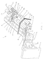
- the clamping unit 1 consists, among other things, of a cross member 2 which is firmly connected to a first left and a first right component 3.
- the components 3 are slidably carried in a further left and a further right component 4.
- the component 4 is pivotally connected to the respective side wall 5 and can be locked on the side wall 5 by connecting elements (not shown) via the elongated holes 5a and, for example, threaded holes not visible here.
- Each component 4 forms a longitudinal groove 4a and elongated holes 4b for connection to the respective component 3, by means of which and by means of connecting elements (not shown) the component 3 can be positioned on the component 4 at a desired distance from the technical and tissue imaging organs (not shown).
- end shields 6 On the cross member 2 are at least several end shields 6 over its length however, a first outer and a second outer bearing plate 6 are arranged. All end shields 6 lie in a common arrangement level.
- the individual end shields 6 receive at their free end a lever 8 arranged pivotably about an axis of rotation 7 and parallel to it a lever 9 arranged in a rotationally fixed manner. Both levers form a roller bearing 8a, 9a.
- the roller roller 10 is loosely carried in the roller bearing 8a of the pivotably arranged lever 8 and the deflection roller 11 is loosely carried in the roller bearing 9a of the non-rotatable lever 9.
- All end shields 6 are transverse in the area of their connection to the cross member 2 penetrated by a shaft 12 adjustable about its longitudinal axis 12a or the Shaft 12 is received in corresponding bearings and e.g. with little sens one of the end shields 6 can be locked.
- the tensioning unit 1 also has a torque compensation in order to rule out any asymmetrical loading on the warp 15.
- a roller bearing carrying a roll neck 10a is inserted into the two free ends of the coating roller 10.
- a roller bearing 17 is also integrated, which rotatably receives a so-called stabilizer shaft 18, which passes through the deflection roller without contact, on its shaft journal 18a.
- a tab 19 establishes an operative connection between the rotatably mounted stabilizer shaft 18 and the respective roll neck 10a.
- connection between the roll neck 10a and the tab 19 is carried out in such a way that the tab 19 has a longitudinal guide 19a into which the roll neck 10a, which has corresponding guide surfaces 10b, engages.
- a positive connection for example a screw connection 20, between the respective shaft journal 18a and the tab 19.
Landscapes
- Engineering & Computer Science (AREA)
- Textile Engineering (AREA)
- Looms (AREA)
Claims (4)
- Dispositif non commandé de tension de la chaíne d'un métier à tisser, constitué deun rouleau étendeur (10) situé du côté de l'ensouple, soutenu dans des paliers-flasques (6), s'étendant sur toute la largeur de tissage du métier à tisser et soumis à l'action d'éléments élastiques (14),un rouleau de changement de direction (11) disposé avec son axe parallèle à celui du rouleau étendeur (10) et soutenu dans des paliers-flasques (6),un premier composant (4) dispose sur chaque montant latéral (5) du métier à tisser, avec liberté de pivoter et d'être bloqué,un second composant (3) qui peut coulisser, sensiblement horizontalement, sur le premier composant en question (4) et y être bloqué, dans lequel les seconds composants (3) sont solidarisés par une traverse (2) s'étendant sur toute la largeur de tissage et dans lequel en outre les paliers-flasques (6) sont disposés sur la traverse (2), à une certaine distance l'un de l'autre sur la longueur de la traverse, caractérisé par le fait quechaque palier-flasque présente, dans la zone de son extrémité libre, un premier levier (8) porté avec liberté de rotation et un second levier (9) relié, sans liberté de rotation, au palier-flasque (6), et chaque levier (8,9) forme un palier (8a,9a) pour porter, sans aucune fixation, le rouleau étendeur et le rouleau de changement de direction (10, 11),il y a un arbre (12) qui traverse les paliers-flasques (6), qui peut pivoter autour de son axe longitudinal (12a), qui peut se bloquer dans un composant fixe par rapport au métier à tisser et qui possède les éléments d'articulation (13) pour les éléments élastiques (14), éléments élastiques qui réalisent une liaison positive avec l'arbre (12) et avec chaque levier (8) etil y a des éléments de compensation (16,17,18,18a,19,19a,20) qui, en présence d'une contrainte dissymétrique du rouleau étendeur (10), opèrent une compensation des mouvements de rotation à l'intérieur du dispositif de tension.
- Dispositif de tension selon la revendication 1, caractérisé par le fait que les paliers (8a,9a) sont au choix conçus comme paliers lisses ou paliers à rouleaux.
- Dispositif de tension selon la revendication 1, caractérisé par le fait que les éléments de compensation sont constitués d'un tourillon (10a) porté dans les extrémités du rouleau étendeur (10), d'un tourillon (18a), porté dans les extrémités du rouleau de changement de direction (11), d'un arbre stabilisaleur (18) et d'une barrette (19) reliant les tourillons respectifs (10a, 18a).
- Dispositif de tension selon la revendication 3, caractérisé par le fait que l'extrémité libre de chaque tourillon (10a) vient en prise dans un guidage longitudinal (19a) prévu dans la zone d'extrémité de la barrette (19) et que l'autre zone d'extrémité de chaque barrette est reliée, par complémentarité de forme, avec le tourillon (18a) de l'arbre stabilisateur (18).
Applications Claiming Priority (2)
| Application Number | Priority Date | Filing Date | Title |
|---|---|---|---|
| DE19538121 | 1995-10-13 | ||
| DE19538121A DE19538121C1 (de) | 1995-10-13 | 1995-10-13 | Ungesteuerte Spanneinheit für die Webkette einer Webmaschine |
Publications (2)
| Publication Number | Publication Date |
|---|---|
| EP0771896A1 EP0771896A1 (fr) | 1997-05-07 |
| EP0771896B1 true EP0771896B1 (fr) | 1999-12-22 |
Family
ID=7774742
Family Applications (1)
| Application Number | Title | Priority Date | Filing Date |
|---|---|---|---|
| EP96113973A Expired - Lifetime EP0771896B1 (fr) | 1995-10-13 | 1996-08-31 | Dispositif non commandé de tension de la chaíne d'un métier à tisser |
Country Status (4)
| Country | Link |
|---|---|
| US (1) | US5755268A (fr) |
| EP (1) | EP0771896B1 (fr) |
| JP (1) | JP2983473B2 (fr) |
| DE (2) | DE19538121C1 (fr) |
Families Citing this family (5)
| Publication number | Priority date | Publication date | Assignee | Title |
|---|---|---|---|---|
| BE1011184A3 (nl) * | 1997-05-28 | 1999-06-01 | Picanol Nv | Inrichting voor het bepalen van de kettingspanning. |
| DE19740309A1 (de) * | 1997-09-13 | 1999-06-10 | Dornier Gmbh Lindauer | Verfahren und Vorrichtung zum Einstellen eines Streichbaums und Kettwächters einer Webmaschine zur Erzeugung einer bestimmten Fachgeometrie |
| IT1304112B1 (it) * | 1998-12-17 | 2001-03-07 | Vamatex Nuova Spa | Portafili a sospensione progressiva per telaio di tessitura |
| RU2404303C2 (ru) * | 2008-08-07 | 2010-11-20 | Государственное образовательное учреждение высшего профессионального образования "Ивановская государственная текстильная академия" (ИГТА) | Способ регулирования натяжения основных нитей и устройство для его осуществления |
| CN112030327B (zh) * | 2020-09-14 | 2021-11-16 | 丹阳市益讯机械有限公司 | 一种织布机的纱线张力调控装置 |
Family Cites Families (11)
| Publication number | Priority date | Publication date | Assignee | Title |
|---|---|---|---|---|
| US3395736A (en) * | 1966-06-22 | 1968-08-06 | Toyoda Automatic Loom Works | Apparatus for preventing warp yarn breakage in a loom |
| CH623873A5 (fr) * | 1977-12-02 | 1981-06-30 | Sulzer Ag | |
| DE3273224D1 (en) * | 1982-10-26 | 1986-10-16 | Sulzer Ag | Warp tensioning device on a weaving loom |
| EP0231726B1 (fr) * | 1986-01-13 | 1989-10-11 | GebràDer Sulzer Aktiengesellschaft | Métier à tisser |
| CH681156A5 (fr) * | 1989-05-02 | 1993-01-29 | Sulzer Ag | |
| BE1004624A3 (nl) * | 1990-11-22 | 1992-12-22 | Picanol Nv | Steuninrichting voor de sleep bij een weefmachine. |
| JP2534202Y2 (ja) * | 1991-12-13 | 1997-04-30 | 株式会社豊田自動織機製作所 | 織機における経糸張力検出装置 |
| DE9312957U1 (de) * | 1993-08-30 | 1993-10-14 | Gebra GmbH & Co Gebr. Raderschad KG, 53773 Hennef | Schraubendreher |
| DE4424712A1 (de) * | 1994-07-13 | 1996-01-18 | Basf Ag | Verwendung von Benzaldehyden zum Markieren von Kohlenwasserstoffen |
| DE4427126C2 (de) * | 1994-07-30 | 1998-09-17 | Dornier Gmbh Lindauer | Spanneinheit für die Webkette in einer Webmaschine |
| DE4427129C2 (de) * | 1994-07-30 | 1998-07-30 | Dornier Gmbh Lindauer | Spanneinheit für die Webkette einer Webmaschine |
-
1995
- 1995-10-13 DE DE19538121A patent/DE19538121C1/de not_active Expired - Fee Related
-
1996
- 1996-08-28 JP JP8226560A patent/JP2983473B2/ja not_active Expired - Fee Related
- 1996-08-31 EP EP96113973A patent/EP0771896B1/fr not_active Expired - Lifetime
- 1996-08-31 DE DE59603973T patent/DE59603973D1/de not_active Expired - Fee Related
- 1996-09-30 US US08/723,532 patent/US5755268A/en not_active Expired - Fee Related
Also Published As
| Publication number | Publication date |
|---|---|
| JPH09111599A (ja) | 1997-04-28 |
| EP0771896A1 (fr) | 1997-05-07 |
| DE19538121C1 (de) | 1997-02-27 |
| JP2983473B2 (ja) | 1999-11-29 |
| US5755268A (en) | 1998-05-26 |
| DE59603973D1 (de) | 2000-01-27 |
Similar Documents
| Publication | Publication Date | Title |
|---|---|---|
| EP0109472B1 (fr) | Dispositif pour tendre la chaîne à une machine à tisser | |
| EP1008683B1 (fr) | Procédé pour compenser le changement de la longueur et de la tension de la chaíne et métier à tisser pour la mise en oeuvre du procédé | |
| EP0396501B1 (fr) | Machine à tisser avec dispositif de tension flexible pour chaîne | |
| DE3933503A1 (de) | Kettfaden-spannvorrichtung fuer einen webstuhl | |
| DE4427129C2 (de) | Spanneinheit für die Webkette einer Webmaschine | |
| EP0771896B1 (fr) | Dispositif non commandé de tension de la chaíne d'un métier à tisser | |
| EP0707103B1 (fr) | Dispositif de tension de la chaíne pour metier à tisser | |
| EP1678359A1 (fr) | Mecanisme de retenue pour un dispositif de surveillance de qualite d'un metier a tisser | |
| DE3533336A1 (de) | Einrichtung zum bewirken der schaftbewegung in einer webmaschine | |
| EP0789097B1 (fr) | Procédé et dispositif pour mesurer la tension de la chaíne dans un métier à tisser | |
| DE3216903C2 (de) | Vorrichtung zur Einstellung der Spannung eines Spannbaumes an einer Webmaschine | |
| DE3029793A1 (de) | Vorrichtung zur spannungsregulierung an einer kettfaedenschicht in einer webmaschine | |
| DE19856308B4 (de) | Verfahren zur Kompensation der Längungs- oder Spannungsänderung in einer Webkette und Webmaschine zur Durchführung des Verfahrens | |
| DE69623383T2 (de) | Fadenwahlvorrichtung | |
| DE602004012004T2 (de) | Anordnung des Streichbaums in einer Webmaschine | |
| DE60030609T2 (de) | Verstellbare Gewebestütze für Webmaschinen | |
| EP0572753A1 (fr) | Métier à tisser avec ensouples sectionnelles | |
| EP3529404B1 (fr) | Dispositif de mesure de la tension de chaîne dans une machine à tisser et machine à tisser équipée d'un tel dispositif | |
| DE19626417A1 (de) | Frottierwebmaschine mit Florkettspannungskompensation | |
| DE69707352T2 (de) | Kettfadenführungsrolle aus Verbundmaterial für Webmaschinen | |
| DE1953470A1 (de) | Einrichtung zum Verlagern der Grundkette bei Frottierwebstuehlen | |
| EP4516646A1 (fr) | Suspension de cabine | |
| DE2418084A1 (de) | Vorrichtung zum steuern der spannung eines laufenden fadens | |
| DE2908297A1 (de) | Sitz mit federndem lehnenteil und/oder aufsitzteil sowie drehfederung | |
| DE8909911U1 (de) | Vorrichtung zum Glätten von Kleidungsstücken |
Legal Events
| Date | Code | Title | Description |
|---|---|---|---|
| PUAI | Public reference made under article 153(3) epc to a published international application that has entered the european phase |
Free format text: ORIGINAL CODE: 0009012 |
|
| AK | Designated contracting states |
Kind code of ref document: A1 Designated state(s): BE CH DE FR GB IT LI |
|
| 17P | Request for examination filed |
Effective date: 19971014 |
|
| 17Q | First examination report despatched |
Effective date: 19971127 |
|
| GRAG | Despatch of communication of intention to grant |
Free format text: ORIGINAL CODE: EPIDOS AGRA |
|
| GRAG | Despatch of communication of intention to grant |
Free format text: ORIGINAL CODE: EPIDOS AGRA |
|
| GRAH | Despatch of communication of intention to grant a patent |
Free format text: ORIGINAL CODE: EPIDOS IGRA |
|
| GRAH | Despatch of communication of intention to grant a patent |
Free format text: ORIGINAL CODE: EPIDOS IGRA |
|
| GRAA | (expected) grant |
Free format text: ORIGINAL CODE: 0009210 |
|
| AK | Designated contracting states |
Kind code of ref document: B1 Designated state(s): BE CH DE FR GB IT LI |
|
| REG | Reference to a national code |
Ref country code: CH Ref legal event code: EP |
|
| REF | Corresponds to: |
Ref document number: 59603973 Country of ref document: DE Date of ref document: 20000127 |
|
| REG | Reference to a national code |
Ref country code: CH Ref legal event code: NV Representative=s name: DIPL.-ING. ETH H. R. WERFFELI PATENTANWALT |
|
| ITF | It: translation for a ep patent filed | ||
| ET | Fr: translation filed | ||
| GBT | Gb: translation of ep patent filed (gb section 77(6)(a)/1977) |
Effective date: 20000323 |
|
| PLBE | No opposition filed within time limit |
Free format text: ORIGINAL CODE: 0009261 |
|
| STAA | Information on the status of an ep patent application or granted ep patent |
Free format text: STATUS: NO OPPOSITION FILED WITHIN TIME LIMIT |
|
| 26N | No opposition filed | ||
| REG | Reference to a national code |
Ref country code: GB Ref legal event code: IF02 |
|
| PGFP | Annual fee paid to national office [announced via postgrant information from national office to epo] |
Ref country code: FR Payment date: 20040623 Year of fee payment: 9 |
|
| PGFP | Annual fee paid to national office [announced via postgrant information from national office to epo] |
Ref country code: GB Payment date: 20040625 Year of fee payment: 9 |
|
| PGFP | Annual fee paid to national office [announced via postgrant information from national office to epo] |
Ref country code: DE Payment date: 20040628 Year of fee payment: 9 |
|
| PGFP | Annual fee paid to national office [announced via postgrant information from national office to epo] |
Ref country code: BE Payment date: 20040713 Year of fee payment: 9 |
|
| PGFP | Annual fee paid to national office [announced via postgrant information from national office to epo] |
Ref country code: CH Payment date: 20041130 Year of fee payment: 9 |
|
| PG25 | Lapsed in a contracting state [announced via postgrant information from national office to epo] |
Ref country code: LI Free format text: LAPSE BECAUSE OF NON-PAYMENT OF DUE FEES Effective date: 20050831 Ref country code: IT Free format text: LAPSE BECAUSE OF NON-PAYMENT OF DUE FEES;WARNING: LAPSES OF ITALIAN PATENTS WITH EFFECTIVE DATE BEFORE 2007 MAY HAVE OCCURRED AT ANY TIME BEFORE 2007. THE CORRECT EFFECTIVE DATE MAY BE DIFFERENT FROM THE ONE RECORDED. Effective date: 20050831 Ref country code: GB Free format text: LAPSE BECAUSE OF NON-PAYMENT OF DUE FEES Effective date: 20050831 Ref country code: CH Free format text: LAPSE BECAUSE OF NON-PAYMENT OF DUE FEES Effective date: 20050831 Ref country code: BE Free format text: LAPSE BECAUSE OF NON-PAYMENT OF DUE FEES Effective date: 20050831 |
|
| PG25 | Lapsed in a contracting state [announced via postgrant information from national office to epo] |
Ref country code: DE Free format text: LAPSE BECAUSE OF NON-PAYMENT OF DUE FEES Effective date: 20060301 |
|
| REG | Reference to a national code |
Ref country code: CH Ref legal event code: PL |
|
| GBPC | Gb: european patent ceased through non-payment of renewal fee |
Effective date: 20050831 |
|
| PG25 | Lapsed in a contracting state [announced via postgrant information from national office to epo] |
Ref country code: FR Free format text: LAPSE BECAUSE OF NON-PAYMENT OF DUE FEES Effective date: 20060428 |
|
| REG | Reference to a national code |
Ref country code: FR Ref legal event code: ST Effective date: 20060428 |
|
| BERE | Be: lapsed |
Owner name: *LINDAUER DORNIER G.M.B.H. Effective date: 20050831 |