EP0771896B1 - Ungesteuerte Spanneinheit für die Webkette einer Webmaschine - Google Patents
Ungesteuerte Spanneinheit für die Webkette einer Webmaschine Download PDFInfo
- Publication number
- EP0771896B1 EP0771896B1 EP96113973A EP96113973A EP0771896B1 EP 0771896 B1 EP0771896 B1 EP 0771896B1 EP 96113973 A EP96113973 A EP 96113973A EP 96113973 A EP96113973 A EP 96113973A EP 0771896 B1 EP0771896 B1 EP 0771896B1
- Authority
- EP
- European Patent Office
- Prior art keywords
- roll
- shaft
- lever
- warp
- journal
- Prior art date
- Legal status (The legal status is an assumption and is not a legal conclusion. Google has not performed a legal analysis and makes no representation as to the accuracy of the status listed.)
- Expired - Lifetime
Links
- 239000003381 stabilizer Substances 0.000 claims description 6
- 239000004744 fabric Substances 0.000 claims description 3
- 239000011248 coating agent Substances 0.000 description 10
- 238000000576 coating method Methods 0.000 description 10
- 238000009941 weaving Methods 0.000 description 8
- 238000010276 construction Methods 0.000 description 1
- 238000003384 imaging method Methods 0.000 description 1
- 230000007257 malfunction Effects 0.000 description 1
- 210000000056 organ Anatomy 0.000 description 1
Images

Classifications
-
- D—TEXTILES; PAPER
- D03—WEAVING
- D03D—WOVEN FABRICS; METHODS OF WEAVING; LOOMS
- D03D49/00—Details or constructional features not specially adapted for looms of a particular type
- D03D49/04—Control of the tension in warp or cloth
- D03D49/12—Controlling warp tension by means other than let-off mechanisms
Definitions
- the invention relates to an uncontrolled tensioning unit of a weaving machine, for a warp consisting of tear-sensitive warp threads.
- a weaving machine with a smooth-running tensioning device for the warp is known from EP application 0 396 501.
- the task of the tensioning device here is to create a smoothly driven tensioning system for a warp that is also suitable for heavy fabrics and is sensitive to tension fluctuations in the warp or changes in position in the drive of the system.
- the object is achieved in that an adjusting mechanism, consisting of a length-adjustable push rod, which is connected to a drive derived from the main drive of the loom and the adjusting mechanism acts on a spring connected to a drive shaft, which is designed as a torsion bar.
- the drive shaft which is operatively connected to the torsion bar, carries a rotationally symmetrical coating or tensioning roller in bearing points distributed over the weaving width.
- EP 0 231 726 A1 also known from EP 0 231 726 A1, which is considered to be the closest prior art, is a tensioning unit for the warp, which is received by a carrying and adjusting device and the carrying and adjusting device on a parallel to the coating or tensioning roller Support element is mounted, which is rotatable and fixable relative to the weaving machine frame, and wherein several support arms are attached to the support element, which carry the tensioning unit.
- EP 0 231 726 A1 does not disclose how, for example in the case of eccentric weaving, ie in the case of an asymmetrical loading of the coating or tensioning roller, a torque compensation takes place within the tensioning unit in order to achieve a largely constant warp tension over the weaving width.
- Such a constant warp tension is particularly important in the case of tear-sensitive warps in order to keep the frequency of warp thread breaks at a low level.
- the object of the invention is an uncontrolled clamping unit for to create tear-sensitive warp threads of a warp with the simple Way the warp can be tensioned in which the coating and deflection roller Is low-mass, which is based on a conventional support tree on which the coating roller supports, dispenses, in which the coating roller and the deflection roller are loose which is worn in terms of weaving conditions in the vertical and horizontal plane is positionable and a torque compensation in the clamping unit with possibly different loading of the coating roller enables.
- the task is characterized by the characteristic features of Claim 1 solved.
- the clamping unit 1 consists, among other things, of a cross member 2 which is firmly connected to a first left and a first right component 3.
- the components 3 are slidably carried in a further left and a further right component 4.
- the component 4 is pivotally connected to the respective side wall 5 and can be locked on the side wall 5 by connecting elements (not shown) via the elongated holes 5a and, for example, threaded holes not visible here.
- Each component 4 forms a longitudinal groove 4a and elongated holes 4b for connection to the respective component 3, by means of which and by means of connecting elements (not shown) the component 3 can be positioned on the component 4 at a desired distance from the technical and tissue imaging organs (not shown).
- end shields 6 On the cross member 2 are at least several end shields 6 over its length however, a first outer and a second outer bearing plate 6 are arranged. All end shields 6 lie in a common arrangement level.
- the individual end shields 6 receive at their free end a lever 8 arranged pivotably about an axis of rotation 7 and parallel to it a lever 9 arranged in a rotationally fixed manner. Both levers form a roller bearing 8a, 9a.
- the roller roller 10 is loosely carried in the roller bearing 8a of the pivotably arranged lever 8 and the deflection roller 11 is loosely carried in the roller bearing 9a of the non-rotatable lever 9.
- All end shields 6 are transverse in the area of their connection to the cross member 2 penetrated by a shaft 12 adjustable about its longitudinal axis 12a or the Shaft 12 is received in corresponding bearings and e.g. with little sens one of the end shields 6 can be locked.
- the tensioning unit 1 also has a torque compensation in order to rule out any asymmetrical loading on the warp 15.
- a roller bearing carrying a roll neck 10a is inserted into the two free ends of the coating roller 10.
- a roller bearing 17 is also integrated, which rotatably receives a so-called stabilizer shaft 18, which passes through the deflection roller without contact, on its shaft journal 18a.
- a tab 19 establishes an operative connection between the rotatably mounted stabilizer shaft 18 and the respective roll neck 10a.
- connection between the roll neck 10a and the tab 19 is carried out in such a way that the tab 19 has a longitudinal guide 19a into which the roll neck 10a, which has corresponding guide surfaces 10b, engages.
- a positive connection for example a screw connection 20, between the respective shaft journal 18a and the tab 19.
Landscapes
- Engineering & Computer Science (AREA)
- Textile Engineering (AREA)
- Looms (AREA)
Description
Die Aufgabe der Spannvorrichtung besteht hier darin, ein leichtgängig angetriebenes Spannsystem für eine Webkette zu schaffen, das auch für schweres Gewebe geeignet ist und sensibel auf Spannungsschwankungen in der Kette bzw. auf Positionsänderungen im Antrieb des Systems reagiert.
Gelöst wird die Aufgabe dadurch, daß ein Verstellmechanismus, bestehend aus einer längeneinstellbaren Schubstange, die mit einem vom Hauptantrieb der Webmaschine abgeleiteten Antrieb in Verbindung steht und der Verstellmechanismus auf eine mit einer Antriebswelle in Verbindung stehenden Feder wirkt, die als Torsionsstab ausgebildet ist.
Die mit dem Torsionsstab wirkverbundene Antriebswelle trägt in über die Webbreite verteilten Lagerstellen eine rotationssymmetrisch ausgebildete Streich- oder Spannwalze.
In der EP 0 231 726 A1 wird nicht offenbart, wie z.B. bei außermittigem Weben, d.h. bei einer asymmetrischen Belastung der Streich- oder Spannwalze, ein Drehmomentenausgleich innerhalb der Spanneinheit erfolgt, um eine weitgehend konstante Kettspannung über die Webbreite zu erreichen.
Eine solche konstante Kettspannung ist insbesondere bei reißempfindlichen Webketten von Bedeutung, um die Häufigkeit von Kettfadenbrüchen auf niedrigem Niveau zu halten.
Es zeigen:
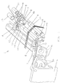
- Figur 1:
- die Anordnung der Spanneinheit an der einen Seitenwange der Webmaschine in perspektivischer Darstellung,
- Figur 2:
- in schematischer Darstellung die Vorkehrungen zum Drehmomenten ausgleich innerhalb der Spanneinheit.
Das Bauteil 4 ist schwenkbeweglich mit der jeweiligen Seitenwand 5 verbunden und durch nicht dargestellte Verbindungselemente über die Langlöcher 5a und z.B. hier nicht sichtbare Gewindelöcher an der Seitenwand 5 arretierbar.
Jedes Bauteil 4 bildet zur Verbindung mit dem jeweiligen Bauteil 3 eine Längsnut 4a und Langlöcher 4b aus, vermittels derer und mittels durch nicht dargestellte Verbindungselemente das Bauteil 3 am Bauteil 4 in einem gewünschten Abstand zu den nicht gezeigten Fach- und Gewebebildeorganen positioniert werden kann.
Beide Hebel bilden ein Rollenlager 8a, 9a aus.
In dem Rollenlager 8a der schwenkbar angeordneten Hebel 8 ist lose die Streichwalze 10 und in dem Rollenlager 9a des drehfesten Hebels 9 ist lose die Umlenkwalze 11 getragen.
Zwischen der verstellbaren Welle 12 und dem jeweiligen Hebel 8 besteht dabei über das jeweilige Federelement 14 eine kraftschlüssige Verbindung.
Dazu ist erfindungsgemäß vorgesehen, wie Figur 2 im Detail zeigt, daß in die beiden freien Enden der Streichwalze 10 ein einen Walzenzapfen 10a tragendes Rollenlager eingesetzt ist.
In den freien Enden der Umlenkwalze 11 ist ebenfalls ein Rollenlager 17 integriert, welches eine sogenannte, die Umlenkwalze berührungslos durchgreifende Stabilisatorwelle 18 an ihren Wellenzapfen 18a drehbeweglich aufnimmt.
Eine Lasche 19 stellt zwischen der drehbeweglich gelagerten Stabilisatorwelle 18 und dem jeweiligen Walzenzapfen 10a eine Wirkverbindung her.
Die Verbindung zwischen den Walzenzapfen 10a und der Lasche 19 ist dabei so ausgeführt, daß die Lasche 19 eine Längsführung 19a aufweist, in die der Walzenzapfen 10a, welcher entsprechende Führungsflächen 10b besitzt, eingreift.
Andererseits besteht zwischen dem jeweiligen Wellenzapfen 18a und der Lasche 19 eine formschlüssige Verbindung, z.B. eine Schraubverbindung 20.
Durch eine solche Ausbildung wird bei asymmetrischer Belastung der Spanneinheit 1 über die Stabilisatorwelle 18 ein Drehmomentenausgleich in der Spanneinheit 1 erreicht.
- 01
- Spanneinheit
- 02
- Querträger
- 03
- Bauteil
- 04
- Bauteil
- 04a
- Längsnut
- 04b
- Langloch
- 05
- Seitenwand
- 05a
- Langloch
- 06
- Lagerschild
- 07
- Drehachse
- 08
- Hebel
- 08a
- Rollenlager
- 09
- Hebel
- 09a
- Rollenlager
- 10
- Streichwalze
- 10a
- Walzenzapfen
- 10b
- Führungsfläche
- 11
- Umlenkwalze
- 12
- Welle
- 12a
- Längsachse
- 13
- Anlenkelement
- 14
- Federelement
- 15
- Webkette
- 16
- Rollenlager
- 17
- Rollenlager
- 18
- Stabilisatorwelle
- 18a
- Wellenzapfen
- 19
- Lasche
- 19a
- Längsführung
- 20
- Schraubverbindung
Claims (4)
- Ungesteuerte Spanneinheit für die Webkette einer Webmaschine, bestehend auseiner in Lagerschilden (6) abgestützten, über die Webbreite der Webmaschine reichenden und unter der Wirkung von Federelementen (14) stehenden kettbaumseitigen Streichwalze (10),einer achsparallel zu der Streichwalze (10) angeordneten und in den Lagerschilden (6) abgestützten Umlenkwalze (11),einem an jeder Seitenwand (5) der Webmaschine schwenkbeweglich und arretierbar angeordneten ersten Bauteil (4),einem zweiten Bauteil (3), das an dem betreffenden ersten Bauteil (4) im wesentlichen horizontal verschiebbar und arretierbar ist, wobei die zweiten Bauteile (3) mit einem über die Webbreite reichenden Querträger (2) fest erbunden sind, und wobei ferner die Lagerschilde (6) beabstandet voneinander über die Querträger-Länge am Querträger (2) angeordnet sind, dadurch gekennzeichnet, daßjedes Lagerschild (6) im Bereich seines freien Endes einen drehbeweglich gelagerten ersten Hebel (8) und einen drehfest mit dem Lagerschild (6) verbundenen zweiten Hebel (9) aufweist, und jeder Hebel (8,9) ein Lager (8a,9a) ausbildet zum losen Tragen der Streich- und der Umlenkwalze (10,11),eine die Lagerschilde (6) quer durchgreifende, um ihre Längsachse (12a) verstellbare und in einem maschinenfesten Bauteil arretierbare Welle (12) vorhanden ist, die Anlenkelemente (13) für die Federelemente (14) besitzt, welche Federelemente mit der Welle (12) und jedem Hebel (8) eine Wirkverbindung herstellen, undAusgleichsglieder (16,17,18,18a,19,19a,20) vorhanden sind, die bei asymmetrischer Belastung der Streichwalze (10) einen Drehmomentenausgleich innerhalb der Spanneinheit bewirken.
- Spanneinheit nach Anspruch 1, dadurch gekennzeichnet, daß die Lager (8a,9a) wahlweise als Gleit- oder Rollenlager ausgebildet sind.
- Spanneinheit nach Anspruch 1, dadurch gekennzeichnet, daß die Ausgleichsglieder aus einem in den Enden der Streichwalze (10) gelagerten Walzenzapfen (10a), aus einem in den Enden der Umlenkwalze (11) gelagerten Wellenzapfen (18a) einer Stabilisatorwelle (18) und aus einer die jeweiligen Zapfen (10a,18a) verbindenden Lasche (19) bestehen.
- Spanneinheit nach Anspruch 3, dadurch gekennzeichnet, daß das freie Ende jedes Walzenzapfens (10a) in eine im Endbereich der Lasche (19) vorhandenen Längsführung (19a) eingreift und der andere Endbereich jeder Lasche mit dem Wellenzapfen (18a) der Stabilisatorwelle (18) formschlüssig verbunden ist.
Applications Claiming Priority (2)
| Application Number | Priority Date | Filing Date | Title |
|---|---|---|---|
| DE19538121 | 1995-10-13 | ||
| DE19538121A DE19538121C1 (de) | 1995-10-13 | 1995-10-13 | Ungesteuerte Spanneinheit für die Webkette einer Webmaschine |
Publications (2)
| Publication Number | Publication Date |
|---|---|
| EP0771896A1 EP0771896A1 (de) | 1997-05-07 |
| EP0771896B1 true EP0771896B1 (de) | 1999-12-22 |
Family
ID=7774742
Family Applications (1)
| Application Number | Title | Priority Date | Filing Date |
|---|---|---|---|
| EP96113973A Expired - Lifetime EP0771896B1 (de) | 1995-10-13 | 1996-08-31 | Ungesteuerte Spanneinheit für die Webkette einer Webmaschine |
Country Status (4)
| Country | Link |
|---|---|
| US (1) | US5755268A (de) |
| EP (1) | EP0771896B1 (de) |
| JP (1) | JP2983473B2 (de) |
| DE (2) | DE19538121C1 (de) |
Families Citing this family (5)
| Publication number | Priority date | Publication date | Assignee | Title |
|---|---|---|---|---|
| BE1011184A3 (nl) * | 1997-05-28 | 1999-06-01 | Picanol Nv | Inrichting voor het bepalen van de kettingspanning. |
| DE19740309A1 (de) * | 1997-09-13 | 1999-06-10 | Dornier Gmbh Lindauer | Verfahren und Vorrichtung zum Einstellen eines Streichbaums und Kettwächters einer Webmaschine zur Erzeugung einer bestimmten Fachgeometrie |
| IT1304112B1 (it) * | 1998-12-17 | 2001-03-07 | Vamatex Nuova Spa | Portafili a sospensione progressiva per telaio di tessitura |
| RU2404303C2 (ru) * | 2008-08-07 | 2010-11-20 | Государственное образовательное учреждение высшего профессионального образования "Ивановская государственная текстильная академия" (ИГТА) | Способ регулирования натяжения основных нитей и устройство для его осуществления |
| CN112030327B (zh) * | 2020-09-14 | 2021-11-16 | 丹阳市益讯机械有限公司 | 一种织布机的纱线张力调控装置 |
Family Cites Families (11)
| Publication number | Priority date | Publication date | Assignee | Title |
|---|---|---|---|---|
| US3395736A (en) * | 1966-06-22 | 1968-08-06 | Toyoda Automatic Loom Works | Apparatus for preventing warp yarn breakage in a loom |
| CH623873A5 (de) * | 1977-12-02 | 1981-06-30 | Sulzer Ag | |
| DE3273224D1 (en) * | 1982-10-26 | 1986-10-16 | Sulzer Ag | Warp tensioning device on a weaving loom |
| EP0231726B1 (de) * | 1986-01-13 | 1989-10-11 | GebràDer Sulzer Aktiengesellschaft | Webmaschine |
| CH681156A5 (de) * | 1989-05-02 | 1993-01-29 | Sulzer Ag | |
| BE1004624A3 (nl) * | 1990-11-22 | 1992-12-22 | Picanol Nv | Steuninrichting voor de sleep bij een weefmachine. |
| JP2534202Y2 (ja) * | 1991-12-13 | 1997-04-30 | 株式会社豊田自動織機製作所 | 織機における経糸張力検出装置 |
| DE9312957U1 (de) * | 1993-08-30 | 1993-10-14 | Gebra GmbH & Co Gebr. Raderschad KG, 53773 Hennef | Schraubendreher |
| DE4424712A1 (de) * | 1994-07-13 | 1996-01-18 | Basf Ag | Verwendung von Benzaldehyden zum Markieren von Kohlenwasserstoffen |
| DE4427126C2 (de) * | 1994-07-30 | 1998-09-17 | Dornier Gmbh Lindauer | Spanneinheit für die Webkette in einer Webmaschine |
| DE4427129C2 (de) * | 1994-07-30 | 1998-07-30 | Dornier Gmbh Lindauer | Spanneinheit für die Webkette einer Webmaschine |
-
1995
- 1995-10-13 DE DE19538121A patent/DE19538121C1/de not_active Expired - Fee Related
-
1996
- 1996-08-28 JP JP8226560A patent/JP2983473B2/ja not_active Expired - Fee Related
- 1996-08-31 EP EP96113973A patent/EP0771896B1/de not_active Expired - Lifetime
- 1996-08-31 DE DE59603973T patent/DE59603973D1/de not_active Expired - Fee Related
- 1996-09-30 US US08/723,532 patent/US5755268A/en not_active Expired - Fee Related
Also Published As
| Publication number | Publication date |
|---|---|
| JPH09111599A (ja) | 1997-04-28 |
| EP0771896A1 (de) | 1997-05-07 |
| DE19538121C1 (de) | 1997-02-27 |
| JP2983473B2 (ja) | 1999-11-29 |
| US5755268A (en) | 1998-05-26 |
| DE59603973D1 (de) | 2000-01-27 |
Similar Documents
| Publication | Publication Date | Title |
|---|---|---|
| EP0109472B1 (de) | Einrichtung zum Spannen einer Webkette an einer Webmaschine | |
| EP1008683B1 (de) | Verfahren zur Kompensation der Längungs- oder Spannungsänderung in einer Webkette und Webmaschine zur Durchführung des Verfahrens | |
| EP0396501B1 (de) | Webmaschine mit leichtgängiger Spannvorrichtung für Webkette | |
| DE3933503A1 (de) | Kettfaden-spannvorrichtung fuer einen webstuhl | |
| DE4427129C2 (de) | Spanneinheit für die Webkette einer Webmaschine | |
| EP0771896B1 (de) | Ungesteuerte Spanneinheit für die Webkette einer Webmaschine | |
| EP0707103B1 (de) | Spanneinheit für die Webkette in einer Webmaschine | |
| EP1678359A1 (de) | Halterung f r eine vorrichtung zur qualit ts berwa chung an einer webmaschine | |
| DE3533336A1 (de) | Einrichtung zum bewirken der schaftbewegung in einer webmaschine | |
| EP0789097B1 (de) | Verfahren und Vorrichtung zum Messen der Spannung der Webkette in einer Webmaschine | |
| DE3216903C2 (de) | Vorrichtung zur Einstellung der Spannung eines Spannbaumes an einer Webmaschine | |
| DE3029793A1 (de) | Vorrichtung zur spannungsregulierung an einer kettfaedenschicht in einer webmaschine | |
| DE19856308B4 (de) | Verfahren zur Kompensation der Längungs- oder Spannungsänderung in einer Webkette und Webmaschine zur Durchführung des Verfahrens | |
| DE69623383T2 (de) | Fadenwahlvorrichtung | |
| DE602004012004T2 (de) | Anordnung des Streichbaums in einer Webmaschine | |
| DE60030609T2 (de) | Verstellbare Gewebestütze für Webmaschinen | |
| EP0572753A1 (de) | Webmaschine mit Teilkettbäumen | |
| EP3529404B1 (de) | Vorrichtung zur messung der kettspannung in einer webmaschine sowie webmaschine mit einer derartigen vorrichtung | |
| DE19626417A1 (de) | Frottierwebmaschine mit Florkettspannungskompensation | |
| DE69707352T2 (de) | Kettfadenführungsrolle aus Verbundmaterial für Webmaschinen | |
| DE1953470A1 (de) | Einrichtung zum Verlagern der Grundkette bei Frottierwebstuehlen | |
| EP4516646A1 (de) | Kabinenlagerung | |
| DE2418084A1 (de) | Vorrichtung zum steuern der spannung eines laufenden fadens | |
| DE2908297A1 (de) | Sitz mit federndem lehnenteil und/oder aufsitzteil sowie drehfederung | |
| DE8909911U1 (de) | Vorrichtung zum Glätten von Kleidungsstücken |
Legal Events
| Date | Code | Title | Description |
|---|---|---|---|
| PUAI | Public reference made under article 153(3) epc to a published international application that has entered the european phase |
Free format text: ORIGINAL CODE: 0009012 |
|
| AK | Designated contracting states |
Kind code of ref document: A1 Designated state(s): BE CH DE FR GB IT LI |
|
| 17P | Request for examination filed |
Effective date: 19971014 |
|
| 17Q | First examination report despatched |
Effective date: 19971127 |
|
| GRAG | Despatch of communication of intention to grant |
Free format text: ORIGINAL CODE: EPIDOS AGRA |
|
| GRAG | Despatch of communication of intention to grant |
Free format text: ORIGINAL CODE: EPIDOS AGRA |
|
| GRAH | Despatch of communication of intention to grant a patent |
Free format text: ORIGINAL CODE: EPIDOS IGRA |
|
| GRAH | Despatch of communication of intention to grant a patent |
Free format text: ORIGINAL CODE: EPIDOS IGRA |
|
| GRAA | (expected) grant |
Free format text: ORIGINAL CODE: 0009210 |
|
| AK | Designated contracting states |
Kind code of ref document: B1 Designated state(s): BE CH DE FR GB IT LI |
|
| REG | Reference to a national code |
Ref country code: CH Ref legal event code: EP |
|
| REF | Corresponds to: |
Ref document number: 59603973 Country of ref document: DE Date of ref document: 20000127 |
|
| REG | Reference to a national code |
Ref country code: CH Ref legal event code: NV Representative=s name: DIPL.-ING. ETH H. R. WERFFELI PATENTANWALT |
|
| ITF | It: translation for a ep patent filed | ||
| ET | Fr: translation filed | ||
| GBT | Gb: translation of ep patent filed (gb section 77(6)(a)/1977) |
Effective date: 20000323 |
|
| PLBE | No opposition filed within time limit |
Free format text: ORIGINAL CODE: 0009261 |
|
| STAA | Information on the status of an ep patent application or granted ep patent |
Free format text: STATUS: NO OPPOSITION FILED WITHIN TIME LIMIT |
|
| 26N | No opposition filed | ||
| REG | Reference to a national code |
Ref country code: GB Ref legal event code: IF02 |
|
| PGFP | Annual fee paid to national office [announced via postgrant information from national office to epo] |
Ref country code: FR Payment date: 20040623 Year of fee payment: 9 |
|
| PGFP | Annual fee paid to national office [announced via postgrant information from national office to epo] |
Ref country code: GB Payment date: 20040625 Year of fee payment: 9 |
|
| PGFP | Annual fee paid to national office [announced via postgrant information from national office to epo] |
Ref country code: DE Payment date: 20040628 Year of fee payment: 9 |
|
| PGFP | Annual fee paid to national office [announced via postgrant information from national office to epo] |
Ref country code: BE Payment date: 20040713 Year of fee payment: 9 |
|
| PGFP | Annual fee paid to national office [announced via postgrant information from national office to epo] |
Ref country code: CH Payment date: 20041130 Year of fee payment: 9 |
|
| PG25 | Lapsed in a contracting state [announced via postgrant information from national office to epo] |
Ref country code: LI Free format text: LAPSE BECAUSE OF NON-PAYMENT OF DUE FEES Effective date: 20050831 Ref country code: IT Free format text: LAPSE BECAUSE OF NON-PAYMENT OF DUE FEES;WARNING: LAPSES OF ITALIAN PATENTS WITH EFFECTIVE DATE BEFORE 2007 MAY HAVE OCCURRED AT ANY TIME BEFORE 2007. THE CORRECT EFFECTIVE DATE MAY BE DIFFERENT FROM THE ONE RECORDED. Effective date: 20050831 Ref country code: GB Free format text: LAPSE BECAUSE OF NON-PAYMENT OF DUE FEES Effective date: 20050831 Ref country code: CH Free format text: LAPSE BECAUSE OF NON-PAYMENT OF DUE FEES Effective date: 20050831 Ref country code: BE Free format text: LAPSE BECAUSE OF NON-PAYMENT OF DUE FEES Effective date: 20050831 |
|
| PG25 | Lapsed in a contracting state [announced via postgrant information from national office to epo] |
Ref country code: DE Free format text: LAPSE BECAUSE OF NON-PAYMENT OF DUE FEES Effective date: 20060301 |
|
| REG | Reference to a national code |
Ref country code: CH Ref legal event code: PL |
|
| GBPC | Gb: european patent ceased through non-payment of renewal fee |
Effective date: 20050831 |
|
| PG25 | Lapsed in a contracting state [announced via postgrant information from national office to epo] |
Ref country code: FR Free format text: LAPSE BECAUSE OF NON-PAYMENT OF DUE FEES Effective date: 20060428 |
|
| REG | Reference to a national code |
Ref country code: FR Ref legal event code: ST Effective date: 20060428 |
|
| BERE | Be: lapsed |
Owner name: *LINDAUER DORNIER G.M.B.H. Effective date: 20050831 |