EP0772989B1 - Dispositif de basculement par une balançoire d'enfant - Google Patents
Dispositif de basculement par une balançoire d'enfant Download PDFInfo
- Publication number
- EP0772989B1 EP0772989B1 EP96116830A EP96116830A EP0772989B1 EP 0772989 B1 EP0772989 B1 EP 0772989B1 EP 96116830 A EP96116830 A EP 96116830A EP 96116830 A EP96116830 A EP 96116830A EP 0772989 B1 EP0772989 B1 EP 0772989B1
- Authority
- EP
- European Patent Office
- Prior art keywords
- drive mechanism
- lifting drive
- rocking
- cradle
- rocking device
- Prior art date
- Legal status (The legal status is an assumption and is not a legal conclusion. Google has not performed a legal analysis and makes no representation as to the accuracy of the status listed.)
- Expired - Lifetime
Links
- 230000033001 locomotion Effects 0.000 claims description 44
- 230000008878 coupling Effects 0.000 claims description 29
- 238000010168 coupling process Methods 0.000 claims description 29
- 238000005859 coupling reaction Methods 0.000 claims description 29
- 230000007246 mechanism Effects 0.000 claims description 17
- 241001465754 Metazoa Species 0.000 claims description 2
- 230000008901 benefit Effects 0.000 description 8
- 208000027418 Wounds and injury Diseases 0.000 description 2
- 230000005540 biological transmission Effects 0.000 description 2
- 230000008859 change Effects 0.000 description 2
- 230000006378 damage Effects 0.000 description 2
- 208000014674 injury Diseases 0.000 description 2
- 239000000725 suspension Substances 0.000 description 2
- 206010038743 Restlessness Diseases 0.000 description 1
- 230000001914 calming effect Effects 0.000 description 1
- 239000011248 coating agent Substances 0.000 description 1
- 238000000576 coating method Methods 0.000 description 1
- 238000010276 construction Methods 0.000 description 1
- 238000006073 displacement reaction Methods 0.000 description 1
- 230000005611 electricity Effects 0.000 description 1
- 238000005516 engineering process Methods 0.000 description 1
- 230000002349 favourable effect Effects 0.000 description 1
- 230000016507 interphase Effects 0.000 description 1
- 238000010030 laminating Methods 0.000 description 1
- 238000013507 mapping Methods 0.000 description 1
- OCDRLZFZBHZTKQ-NMUBGGKPSA-N onetine Chemical compound C[C@@H](O)[C@@]1(O)C[C@@H](C)[C@@](C)(O)C(=O)OC\C2=C\CN(C)CC[C@@H](OC1=O)C2=O OCDRLZFZBHZTKQ-NMUBGGKPSA-N 0.000 description 1
- 239000011435 rock Substances 0.000 description 1
- 230000005612 types of electricity Effects 0.000 description 1
Images



Classifications
-
- A—HUMAN NECESSITIES
- A47—FURNITURE; DOMESTIC ARTICLES OR APPLIANCES; COFFEE MILLS; SPICE MILLS; SUCTION CLEANERS IN GENERAL
- A47D—FURNITURE SPECIALLY ADAPTED FOR CHILDREN
- A47D9/00—Cradles ; Bassinets
- A47D9/02—Cradles ; Bassinets with rocking mechanisms
- A47D9/04—Cradles ; Bassinets with rocking mechanisms with disconnectable rockers
-
- A—HUMAN NECESSITIES
- A47—FURNITURE; DOMESTIC ARTICLES OR APPLIANCES; COFFEE MILLS; SPICE MILLS; SUCTION CLEANERS IN GENERAL
- A47D—FURNITURE SPECIALLY ADAPTED FOR CHILDREN
- A47D13/00—Other nursery furniture
- A47D13/02—Baby-carriers; Carry-cots
- A47D13/027—Baby-carriers with rigid frames
-
- A—HUMAN NECESSITIES
- A47—FURNITURE; DOMESTIC ARTICLES OR APPLIANCES; COFFEE MILLS; SPICE MILLS; SUCTION CLEANERS IN GENERAL
- A47D—FURNITURE SPECIALLY ADAPTED FOR CHILDREN
- A47D13/00—Other nursery furniture
- A47D13/10—Rocking-chairs; Indoor Swings ; Baby bouncers
- A47D13/102—Rocking-chairs; Indoor Swings ; Baby bouncers with curved rocking members resting on the ground
-
- A—HUMAN NECESSITIES
- A47—FURNITURE; DOMESTIC ARTICLES OR APPLIANCES; COFFEE MILLS; SPICE MILLS; SUCTION CLEANERS IN GENERAL
- A47D—FURNITURE SPECIALLY ADAPTED FOR CHILDREN
- A47D9/00—Cradles ; Bassinets
- A47D9/02—Cradles ; Bassinets with rocking mechanisms
- A47D9/053—Cradles ; Bassinets with rocking mechanisms with curved rocking member
-
- A—HUMAN NECESSITIES
- A47—FURNITURE; DOMESTIC ARTICLES OR APPLIANCES; COFFEE MILLS; SPICE MILLS; SUCTION CLEANERS IN GENERAL
- A47D—FURNITURE SPECIALLY ADAPTED FOR CHILDREN
- A47D9/00—Cradles ; Bassinets
- A47D9/02—Cradles ; Bassinets with rocking mechanisms
- A47D9/057—Cradles ; Bassinets with rocking mechanisms driven by electric motors
-
- A—HUMAN NECESSITIES
- A63—SPORTS; GAMES; AMUSEMENTS
- A63G—MERRY-GO-ROUNDS; SWINGS; ROCKING-HORSES; CHUTES; SWITCHBACKS; SIMILAR DEVICES FOR PUBLIC AMUSEMENT
- A63G13/00—Cradle swings; Rocking-horses; Like devices resting on the ground
-
- B—PERFORMING OPERATIONS; TRANSPORTING
- B62—LAND VEHICLES FOR TRAVELLING OTHERWISE THAN ON RAILS
- B62B—HAND-PROPELLED VEHICLES, e.g. HAND CARTS OR PERAMBULATORS; SLEDGES
- B62B9/00—Accessories or details specially adapted for children's carriages or perambulators
- B62B9/22—Devices for rocking or oscillating
Definitions
- the present invention relates to a device for generating a Rocking movement in seesaws and the like according to the generic term of claim 1. With the help of such devices, it is possible Strollers and the like in a smooth rocking motion to move so as to calm the child without the supervisor must act itself.
- Such an automatic rocking device is, for example, from from US-A-4 985 949:
- the rocking device is expediently to the same level as the seesaw - from the example below, but is not meant to be exclusive - so that the Stroke movement of the coupling member directly to a change in height of the Part of the rocker leads, which is fixed to the coupling member, from which the desired rocking movement results.
- Attaching the rocking device on the seesaw is as simple as removing it: Man simply place the rocking device under one of the rocker runners or under a crossbar between the two runners, so that the coupling member comes into engagement with the rocker.
- a wind-up music box is provided, to further calm the child in addition to a rocking motion by playing music.
- Disadvantage of this wind-up Music box is the very limited playing time, so the one you want Calming effect due to an early and abrupt end to the Music is picked up again.
- rocking device known from DE-A-25 41 935 the The disadvantage of the limited playing time of a music box avoided that the music box is coupled directly to the swing drive and thereby always runs when the swing drive is working.
- This rocking device is otherwise constructed as follows: the rocking device is attached via special inelastic fastening lines between the axis a stroller and the push handle mounted and braced.
- the Rocking device itself consists of an eccentric drive that over a linkage generates a lifting movement and with the help of the fastening lines the distance between the axis and push handle changes continuously, which results in a rocking movement of the stroller.
- the main disadvantage of this braced between the axis and push handle Rocking device is that the suspension of the Stroller is lost, which is necessary to uneven floors intercept opposite the stroller basket. Accordingly, the Pushing the stroller has the advantage of being forced evenly Rocking with the disadvantage of lost suspension and thus bought a more restless driving behavior, which leads to that the pushing device pushing the stroller over longer distances together with the fastening lines must be removed under simultaneous preloading of the distance between push handle and axle.
- the present invention is based on the object the known rocking devices with music box in terms of their functionality continue to improve.
- This object is achieved according to the invention by the features of the characterizing part of claim 1.
- a Such swing drive has the great advantage that the music box can also be deactivated due to their solvability, i.e. a Rocking without noise is possible.
- the swing drive can also be used for the music box play different melodies, which significantly increases the Acceptance and use of the rocking device contributes.
- the present invention not only takes advantage of the prior art Technology bypassing the associated disadvantages, but it enables in addition, the user also has the choice of how long and with which melody the music box should run.
- the fork is not driven along a pure vertical stroke, but to be rotatably displaced by an eccentric they move their position with the one above the other during their rotation Can maintain tines. In both cases, such a positive Coupling ensure that the rocker is in every position of the lifting movement the rocking device follows.
- the detachable connection is particularly favorable between coupling member and rocker by the following, with respect the construction effort even simpler definition variant to realize:
- Position of the rocking device below the rocker can the weight of the rocker to plant between Coupling link and rocker can be used. This must the point of contact of the seesaw by its weight are always pressed in the direction of the coupling element, a constant connection and thus a continuous transmission of the lifting movement to the Ensure seesaw.
- the coupling member can in this case be designed as a simple lever that attacks from below on the seesaw, because only one more Pressure or support force needs to be generated.
- the solution according to the invention not only ensures that easy attachment and removal of the rocking device from the seesaw, but also allows also versatile use with seesaw or swing elements such as B. in a stroller where the rocking device in a simple way under one of the two wheel axles can be positioned, whereupon the lifting movement of the rocking device is a rocking movement of the entire stroller.
- the Swing movement can even be on unsprung strollers be transmitted.
- Carrying bags and the like can be the invention Rocking device applied in a simple manner , but always the size of the Rocking device in proportion to the Size of the rocking element to be lifted must be.
- the lifting drive advantageously comprises a Eccentric with eccentrically mounted coupling element in Shape of an approximately horizontally protruding bolt.
- This Bolts can be provided with a low-friction coating be so that it does not make any disturbing noises when circulating through its attachment to the corresponding Causes rocking or the pin carries a ball bearing, whose outer ring engages with the rocker part stands.
- a (small) electric motor is used to design the linear actuator considered by gears, a Worm drive or the like is reduced. Instead can also use a finished geared motor become.
- rocking device itself is adjustable in height, whereby adapted to the respective areas of application and also quickly converted for another application can be.
- This height adjustment can, for example in a screwing device or in plug inserts consist.
- An essential advantage of the present invention is given when the drive parts of the linear actuator are surrounded by a housing to avoid any risk of injury by intervening in the moving To prevent parts. Especially when using a This ensures that the eccentric drive the large driving forces exerted by the drive member be safely shielded from the environment.
- connection of the coupling member with the rocker is shielded by, for example, the rocker during the stroke movement dips into the housing.
- a rocking device next to a linear actuator has a music box, which is convenient at least indirectly coupled to the linear actuator and can be actuated by the movement of the linear actuator.
- the coupling can take place mechanically in a mechanically actuated music box, so that the Music box with a drive link assigned to it a gear member of the linear actuator is engaged and only runs when the linear actuator is running is operated.
- this coupling can also done electronically, including the music box can consist of a microchip.
- the mechanically operated music box uses the mechanical coupling already existing components of the Hubantriebes and does not offer the lifting movement greater resistance.
- the noise level is also guaranteed here with the linear actuator connected music box that a noise through the music box only during the swing phase, So while the child is to be calmed down, while the music box is not in the resting phase is working.
- the Music box is designed to be detachable and replaceable, whereby on the one hand for a silent lifting movement from the Engagement with the linear actuator can be brought and exchanged for another music box and so different with the same rocking device Melodies can be played.
- this is advantageously a human or animal head modeled on the one hand to emphasize the essential functions and their enable easier mapping, and to differentiate yourself the environment, which is usually child-friendly to adapt to a seesaw.
- the rocking device with a switch for switching the linear actuator on / off provided, this can be part of the head-shaped rocking device can be integrated, for example in the nose.
- This part of the head can also serve to hold the music box, in this case, the entire switch together can be replaced with the music box.
- the switch can be switched on / off furthermore used to actuate the Control music box and its coupling with the linear actuator.
- the rocking device is designed or may be equipped, in any case it is advisable this to adapt the point of attack of the linear actuator height adjustable on the rocker.
- This can be done vertically against each other, for example displaceable housing parts take place, whereby for mutual determination in different height positions corresponding to each other on both housing parts Latching means can be provided.
- Simple Locking means can, for example, in particular resilient toothed rack and an in the rack engaging stop, where the payment bar is best from the outside of the housing is accessible.
- the height can be adjusted, for example, in the housing Neck area can be arranged.
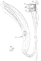
- FIG. 1 a children's seesaw 1 is shown on the free rocker end 2 a rocking device 3 is provided is engaged with a cross bar 2 a stands.
- This rocking device 3 the exact structure can be seen more clearly from FIGS. 2-6, is on the same level 4 as the rocker.
- the rocking device with an appropriate pad to position it a little higher so that the desired one System between the cross bar 2 a of the rocker and the Rocking device is guaranteed.
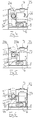
- FIG. 2 shows a rocking device according to the invention 13, which consists of a cylindrical housing 14.
- This housing is for the free rocker runner end 2 a inserted a slot 15 from above, along which the skid according to the lifting movement of the rocking device can move.
- the lifting movement itself is from a linear actuator 16 generated from a small motor 17, from a worm 18, a spur gear 19 and one eccentrically arranged on the spur gear, approximately horizontally protruding bolt 20 is made.
- transmits the small motor rotates on the screw 18, which in turn is a rotational movement around a perpendicular to it Transmits axis to the spur gear 19, whereby the Bolt 20 is moved on a circular path.
- the seesaw end 2 which is in contact with the pin 20, is thereby according to the changes in altitude, which the bolt traverses on its circular motion, raised or lowered.
- FIG. 3 shows the rocking device 13 from FIG. 2 with the corresponding components in cut Front view.
- FIG. 4 shows an alternative design of a rocking device 23, which shows a lifting drive 26 having.
- This stroke drive 26 consists of a Small gear motor 27, the eccentric 30th drives. While in Figure 2 the bolt 20 is eccentric is arranged on the spur gear 19, but with the central axis the drive shaft coincides with its axis of rotation, is now the central axis of the eccentric disc 30 offset relative to its axis of rotation. Broadcasts here too the small gear motor 27 has a rotary motion the eccentric disc, which is a corresponding change in height the rocker end 2 a and a rocking motion the rocker 1 causes.
- Figure 5 shows another alternative. Doing so the drive motor 27 via an eccentric 27 a thereon rotatably mounted fork 34 with two horizontally protruding and stacked bolts 20 a and 20 b, the rocker end 2 a between them or pick up another part of the rocker.
- the distance between the bolts is appropriate 20 a and 20 b adjustable, for example by a snap or Snap connection or the like to different him Dimensions of the corresponding rocker part 2 a to adapt.
- the Fork 34 in turn rotatable on the eccentric 27 a is mounted so that their rotary movements are a lifting movement generate the fork 34, in the course of which Bolts 20 a and 20 b largely in the vertical direction stay on top of each other.
- FIG. 6 shows a design in which the Small gear motor 27 the rotary movements on the eccentric stored bolt 20 transmits, but in in this case not via a turntable 34, but rather, two crank arms 44 and 45 on both of them Ends is stored.
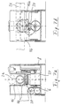
- the design in Figure 7 is characterized in that the coupling member 20 in a movable plunger 46 is stored.
- This stamp is dimensioned so that he the horizontal cross section of the slot 15, in where the lifting movement takes place.
- This Stamp takes part in the lifting movement of the coupling member, however without its lateral movements. He points to this an approximately horizontal slot 46 a, in which the Bolt of the coupling member is mounted and its Length of the horizontal movement of the bolt 20 corresponds. This is how the rotating bolt is touched and thus the risk of a child's finger becoming trapped excluded between the housing and the coupling member.
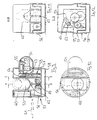
- FIG. 8 shows a further embodiment of a rocking device 51 for a seesaw 52, the Child seesaw with the rocking device over one Handle 53 is engaged.
- the rocking device 51 a shape and an appearance that suits you is modeled on the human head. This leaves the technical character of the rocking device conceal something, but also on the other an illustration of the individual functional parts achieve: Because not only in space highlighted nose 54 of the rocking device both the switch for switching the on / off Linear actuator as well as one - from the following Figures visible - music box 55 arranged.
- a height adjustment device 56 integrated, through which the rocking device in their Basic position to the optimal engagement position of the Children's seesaw is customizable. How clearer from the the following figures can be seen by the Height adjustment device 56 two housing parts 57 and 58 telescopically shifted against or into each other.
- FIG. 9 shows the rocking device 51 in section Representation and clarifies in particular the drive mechanism to generate the lifting movement and Operate the music box.
- An eccentric drive is used for this 59 via a battery 60 or a (dashed line in FIG. 9 shown) low-voltage connector 61 with electricity supplies and transmits the rotary movement of the eccentric drive 59 on an eccentrically mounted one Lifting stamp 62, on which the handle 53 of the rocker 52 rests.
- This jack 62 is by the Eccentric drive 59 moves up and down and generates an Pivoting of the rocker 52 over its underside, causing it to rock.
- a drive member 64 can be mechanically coupled, which the rotational movement on the music box 55 in the coupled Condition transmits.
- the mechanical coupling is special can be seen in Figure 12, the section along the line C-D from Figure 9: Here is in upper area, the drive member 64 on the one hand, dashed and shown with a solid line.
- Drive slide 64 does not engage the transmission link 63 of the eccentric drive 59 while turning the nose 54, also shown in dashed lines a pivot indicated by the arrow in Figure 12 of the drive member 64 leads, at the end the drive member engages the gear member. In this state becomes the drive movement of the eccentric drive 59 on the drive member 64 and thereby transferred to the music box 55.
- Figure 10 shows the rocking device 51 in plan view and in particular together with FIG. 9 the shape of the Recognize reciprocating piston 62, which is also shown in FIG 11 is shown along a sectional view the line A-B from FIG. 9.
- FIGS. 13 to 15 illustrate those in FIG. 8 already indicated and likewise in FIGS. 9 to 11 height adjustment device 56 to be recognized, the from a snap connection between the two arranged housing parts 57 and 58.
- the upper housing half 57 knows a vertical toothed rack 66 with detents arranged one above the other, while lower housing half 58 engages therein appropriately trained stops 67 includes.
- One of the two locking devices must be slightly horizontal be flexible, so that a relative displacement of both housing halves is possible by disengaging each other. is possible.
- the principle used here is in Figure 15 illustrates schematically.
- FIG. 16 and 17 finally show again the pivoting of the already indicated in FIG Nose, whereby the drive member 64 of the music box with the Gear member 63 of the eccentric drive in engagement is feasible.
- the eccentric drive makes a lifting movement on the lifting piston 62 or the rocker 52 transmitted without this noise caused by the music box 55 would.
- the advantages of the present are Invention in that on the one hand a risk of injury by laminating the lifting drive components, largely it is excluded that for the lifting movement anyway required movement of the eccentric drive also used at the same time to drive a music box that runs only when the linear actuator is activated, and finally that the switch to This highlights the switch on / off of the linear actuator or is emphasized that it is in shape and appearance a human head model as well formed in the form of part of this head is. This part can also be used for recording serve the music box, which is conveniently light disassembled and exchanged for another music box can be.
Landscapes
- Engineering & Computer Science (AREA)
- Health & Medical Sciences (AREA)
- Public Health (AREA)
- Chemical & Material Sciences (AREA)
- Combustion & Propulsion (AREA)
- Transportation (AREA)
- Mechanical Engineering (AREA)
- Toys (AREA)
- Chairs For Special Purposes, Such As Reclining Chairs (AREA)
- Tumbler Switches (AREA)
Claims (17)
- Dispositif pour la création d'un mouvement à bascule dans le cas de balançoires pour enfants ou articles similaires, composé d'un entraínement de levage avec élément de couplage, l'élément de couplage (20, 30, 34) de l'entraínement de levage (16, 26) pouvant être engagé directement avec la balançoire (1) de manière amovible sans élément intermédiaire ni travaux de montage, le dispositif à bascule (51) présentant une boíte à musique (55), et la boíte à musique (55) pouvant être actionnée mécaniquement, caractérisé en ce que la boíte à musique (55) est couplée au moins indirectement à l'entraínement de levage (59) et peut être actionnée par le mouvement de l'entraínement de levage, en ce que le couplage est réalisé de façon mécanique, en ce que la boíte à musique présente un élément d'entraínement (64), au moyen duquel elle est en prise avec un organe d'engrenage (63) de l'entraínement de levage (59), et en ce que la boíte à musique (55) est exécutée de façon amovible et est interchangeable.
- Dispositif selon la revendication 1, caractérisé en ce que la forme et l'aspect du dispositif à bascule (51) ressemble à une tête humaine ou une tête d'animal et présente un interrupteur (54), pour la mise en marche et l'arrêt de l'entraínement de levage (59), intégré dans une partie de la tête, notamment dans le nez.
- Dispositif selon la revendication 1 et la revendication 2, caractérisé en ce que la boíte à musique (55) est intégrée dans la partie de la tête présentant l'interrupteur (54).
- Dispositif selon la revendication 2 et la revendication 1, caractérisé en ce que l'interrupteur (54) pour la mise en marche et l'arrêt de l'entraínement de levage (59) commande l'actionnement de la boíte à musique (55).
- Dispositif selon la revendication 1, caractérisé en ce que la prise de l'élément de couplage (20, 30, 34) est réalisée sur la balançoire (1) à l'aide d'une connexion enfichable amovible.
- Dispositif selon la revendication 5, caractérisé en ce que l'élément de couplage est formé comme boulon (20), comme fourche (34) ou comme montant de levage (46).
- Dispositif selon la revendication 1, caractérisé en ce que la prise de l'élément de couplage (20, 30, 46) sur la balançoire (1) est réalisée à l'aide du poids de la balançoire.
- Dispositif selon la revendication 1, caractérisé en ce que l'entraínement de levage (16, 26) présente un excentrique comme élément de couplage (20, 30).
- Dispositif selon la revendication 8, caractérisé en ce que l'excentricité de l'élément de couplage (20, 30) est réglable.
- Dispositif selon la revendication 1, caractérisé en ce que l'entraínement de levage comprend un engrenage à vis sans fin (16).
- Dispositif selon la revendication 1, caractérisé en ce que l'entraínement de levage (26) présente un moteur-réducteur (27).
- Dispositif selon la revendication 1, caractérisé en ce que l'entraínement de levage présente un circuit intermittent.
- Dispositif selon la revendication 1, caractérisé en ce que l'entraínement de levage présente une commande pour le redémarrage automatique, la commande réagissant à un niveau de bruit prédéfini.
- Dispositif selon la revendication 1, caractérisé en ce que l'entraínement de levage (16, 26) est entouré d'un boítier.
- Dispositif selon la revendication 1, caractérisé en ce que le dispositif à bascule (51) est exécuté de façon à être réglable en hauteur pour l'adaptation du point de prise de l'entraínement de levage (59) sur la balançoire pour enfants (52).
- Dispositif selon la revendication 15, caractérisé en ce que le réglage en hauteur est réalisé à l'aide de deux pièces de boítier (57), déplaçables verticalement l'une contre l'autre, qui entourent l'entraínement de levage (59), et en ce que des organes à crans (66, 67) correspondants l'un par rapport à l'autre sont prévus sur les deux pièces de boítier pour la fixation mutuelle à différentes hauteurs.
- Dispositif selon la revendication 16, caractérisé en ce que les organes à crans (66, 67) sont composés d'une crémaillère, notamment d'exécution élastique, et d'une butée ayant prise dans la crémaillère.
Applications Claiming Priority (2)
| Application Number | Priority Date | Filing Date | Title |
|---|---|---|---|
| DE29517900U | 1995-11-11 | ||
| DE29517900U DE29517900U1 (de) | 1995-11-11 | 1995-11-11 | Schaukelantrieb für Kinderwippen |
Publications (2)
| Publication Number | Publication Date |
|---|---|
| EP0772989A1 EP0772989A1 (fr) | 1997-05-14 |
| EP0772989B1 true EP0772989B1 (fr) | 2000-01-26 |
Family
ID=8015313
Family Applications (1)
| Application Number | Title | Priority Date | Filing Date |
|---|---|---|---|
| EP96116830A Expired - Lifetime EP0772989B1 (fr) | 1995-11-11 | 1996-10-19 | Dispositif de basculement par une balançoire d'enfant |
Country Status (3)
| Country | Link |
|---|---|
| US (1) | US5860698A (fr) |
| EP (1) | EP0772989B1 (fr) |
| DE (2) | DE29517900U1 (fr) |
Families Citing this family (31)
| Publication number | Priority date | Publication date | Assignee | Title |
|---|---|---|---|---|
| DE29619352U1 (de) * | 1996-11-07 | 1997-06-12 | Nawrath, Harald, 59075 Hamm | Schaukelwiege mit Motorpendelmechanismus |
| US6378940B1 (en) | 1999-11-08 | 2002-04-30 | Summer Infant Products, Inc. | Bouncer seat and drive mechanism therefor |
| US6412867B2 (en) * | 2000-02-29 | 2002-07-02 | Odessa Robinson | Automatic two speed musical rocking chair |
| US6811217B2 (en) * | 2002-08-15 | 2004-11-02 | Mattel, Inc. | Rocker device |
| USD480884S1 (en) | 2002-08-15 | 2003-10-21 | Mattel, Inc. | Rocker device |
| US20050151401A1 (en) * | 2004-01-13 | 2005-07-14 | Fonda Evans | Child car seat |
| US20050264063A1 (en) * | 2004-05-12 | 2005-12-01 | Diane Babcock | Rocking infant carrier |
| US7037205B1 (en) | 2004-09-01 | 2006-05-02 | Jeffrey Alan Bowman | Baby carrier having an integral swinging mechanism |
| US20070007804A1 (en) * | 2005-03-24 | 2007-01-11 | Cosco Management, Inc. | Juvenile relaxation apparatus with motion system |
| US7845722B1 (en) * | 2005-04-07 | 2010-12-07 | Christopher Manenti | Infant seat base with vehicle travel simulation means for mounting a vehicle infant seat |
| US7537285B2 (en) * | 2005-09-08 | 2009-05-26 | Stewart Laverne L | Device that automatically rocks a rocking a chair and similar articles |
| US7485086B2 (en) * | 2005-12-01 | 2009-02-03 | 3699013 Canada Inc. | Rocking mechanism for children with associated sounds |
| US7546652B1 (en) | 2008-01-23 | 2009-06-16 | Michelle Maloof | Colic swing |
| US20090200846A1 (en) * | 2008-02-13 | 2009-08-13 | Aviezer Yehuda | Infant seat rocker device |
| US20100001566A1 (en) * | 2008-02-13 | 2010-01-07 | Aviezer Yehuda | Rocker device for infant seat |
| AT10668U1 (de) | 2008-08-29 | 2009-08-15 | Blum Gmbh Julius | Gehäuse zur wenigstens teilweisen aufnahme eines möbelbeschlages |
| USD660053S1 (en) | 2010-09-15 | 2012-05-22 | Kids Ii, Inc. | Children's rocker |
| US8795097B2 (en) | 2010-10-07 | 2014-08-05 | Mattel, Inc. | Combination infant rocker and swing |
| US8820834B2 (en) | 2012-02-17 | 2014-09-02 | Brian Stephen Harding | Device and method for imparting a rocking motion to an infant car seat |
| GB2503453A (en) * | 2012-06-25 | 2014-01-01 | Innovative Baby Products Ltd | Baby rocking and multifunctional device |
| US9332847B2 (en) | 2013-01-10 | 2016-05-10 | Arthur Oscar McLellen | Powered rocker system assemble |
| US9119482B2 (en) * | 2013-08-02 | 2015-09-01 | Steve M. Cornmesser | Automatic baby carrier rocking device |
| USD772625S1 (en) | 2014-11-26 | 2016-11-29 | Mattel, Inc. | Infant support structure with a rocking device |
| ES2636807T3 (es) * | 2015-07-13 | 2017-10-09 | Ekide, S.L. | Aparato para mecer coches de bebé u otros dispositivos para bebés que comprenden ruedas |
| US9993081B1 (en) | 2016-04-28 | 2018-06-12 | Arthur Oscar McLellen | Universal powered rocking system |
| USD826592S1 (en) | 2017-06-16 | 2018-08-28 | Kids Ii, Inc. | Child support device |
| USD826590S1 (en) | 2017-06-16 | 2018-08-28 | Kids Ii, Inc. | Child support device |
| USD826591S1 (en) | 2017-06-16 | 2018-08-28 | Kids Ii, Inc. | Child support device |
| US10494009B2 (en) * | 2018-03-06 | 2019-12-03 | Rawan F. H. M. Othman | Stroller rocking device |
| US10448740B1 (en) * | 2018-04-11 | 2019-10-22 | Zenithen USA, LLC | Spring-loaded leg rocking chair |
| US11000128B2 (en) * | 2019-07-26 | 2021-05-11 | Zenithen USA, LLC | Horizontal-moving and rocking appliance and rocking chair |
Family Cites Families (36)
| Publication number | Priority date | Publication date | Assignee | Title |
|---|---|---|---|---|
| US42745A (en) * | 1864-05-17 | Improved baby-tender | ||
| US2689355A (en) * | 1953-05-21 | 1954-09-21 | Frank Russell Frank De | Electric crib rocker |
| US2916745A (en) * | 1954-09-17 | 1959-12-15 | Lesk Norman | Power actuated rhythmical movement accessories for children's cribs |
| US2830815A (en) * | 1955-10-07 | 1958-04-15 | Hawes Alan Bruce | Motor-powered see-saw |
| FR1294774A (fr) * | 1961-03-24 | 1962-06-01 | Procédé permettant d'animer une voiture d'enfant, de mouvements divers | |
| US3139630A (en) * | 1961-06-15 | 1964-07-07 | Max L Hunt | Rhythm rocker |
| FR1323337A (fr) * | 1962-05-24 | 1963-04-05 | Appareil berceur | |
| FR1343876A (fr) * | 1962-11-05 | 1963-11-22 | Appareil à bercer les bébés | |
| US3225365A (en) * | 1964-01-30 | 1965-12-28 | Rock A Bye Company | Crib rocking device |
| FR1501951A (fr) * | 1966-09-30 | 1967-11-18 | Dispositif de bercement automatique pour landaux, berceaux et analogues | |
| US3371358A (en) * | 1967-02-03 | 1968-03-05 | Joseph T. Shackel | Rocking cradle |
| DE7031225U (de) * | 1970-08-20 | 1971-03-25 | Beyrow Wolfgang | Kinderwiege mit einem schaukelantrieb. |
| US3653080A (en) * | 1970-11-23 | 1972-04-04 | Raymond Lee Organization Inc | Rocking infant seat |
| US3818517A (en) * | 1972-10-30 | 1974-06-25 | M Casella | Rocking chair or cradle with rocking mechanism |
| US3851343A (en) * | 1973-08-09 | 1974-12-03 | W Kinslow | Infant seat rocker |
| DE2541935A1 (de) | 1975-09-19 | 1977-03-24 | Brehm | Automatische schaukelvorrichtung fuer kinderwagen |
| US4141095A (en) * | 1976-06-09 | 1979-02-27 | Kouji Adachi | Electronic cradle |
| FR2405674A1 (fr) * | 1977-10-14 | 1979-05-11 | Lepers Jean Gabriel | Dispositif pour bercer les bebes |
| US4501013A (en) * | 1979-09-18 | 1985-02-19 | Olympus Optical Co., Ltd. | Car stereo set |
| ES246723Y (es) * | 1979-11-12 | 1980-09-16 | Dispostivo de acunado | |
| US4634175A (en) * | 1983-11-08 | 1987-01-06 | Gerber Baby Products | Baby carrier |
| US4656680A (en) * | 1985-05-13 | 1987-04-14 | Wilson Roger F | Method and apparatus for oscillating a baby to sleep |
| DE8524462U1 (de) * | 1985-08-27 | 1985-12-19 | Boretius, Waldemar, 6760 Rockenhausen | Querschwingende Kinderwiege |
| IT206435Z2 (it) * | 1986-03-21 | 1987-08-10 | Perego Pines Gmbh | Dispositivo giocattolo, in particolare cavallo animato. |
| US4793010A (en) * | 1987-10-28 | 1988-12-27 | General Ideas & Products Ltd. | Baby rocker apparatus |
| US4987624A (en) * | 1988-03-02 | 1991-01-29 | Nafti David I | Device for imparting multi-directional rocking motion |
| FR2638343A1 (fr) * | 1988-11-02 | 1990-05-04 | Falkowski Richard | Dispositif pour balancer les voitures d'enfants, les berceaux, les balancoires etc. sans intervention manuelle |
| US4985949A (en) * | 1989-09-01 | 1991-01-22 | Jantz Robert F | Infant carrier seat rocker |
| DE9002557U1 (de) * | 1990-03-06 | 1990-08-02 | Polak, Jan, 4800 Bielefeld | Bewegungseinrichtung für Kinderwagen und Kinderwiegen |
| GB9124375D0 (en) * | 1991-11-15 | 1992-01-08 | Bulkan Franklin J | A rocking device |
| DE9202900U1 (de) * | 1992-03-05 | 1992-07-02 | Bill, Rainer, O-4603 Bad Schmiedeberg | Vorrichtung zur kontrollierten Bewegung von Schlafbehältnissen für Säuglinge und Kleinstkinder |
| GB2276539B (en) * | 1993-02-11 | 1996-07-03 | Gerald Albert Oliver | Rocking device |
| DE9313998U1 (de) * | 1993-09-16 | 1993-12-16 | Richter, Knut, Dipl.-Ing., 65933 Frankfurt | Bewegungsvorrichtung für einen Baby-Sitz oder einen anderen Sitz- oder Liegegegenstand mit Schaukelwippe |
| US5482352A (en) * | 1994-09-28 | 1996-01-09 | Leal; Horacio | Child seat with audio |
| US5542587A (en) * | 1994-10-17 | 1996-08-06 | Broz; Jayne I. | Infant carrier installable on a bicycle |
| US5624156A (en) * | 1996-03-25 | 1997-04-29 | Leal; Horacio | Child safety seat with entertainment system |
-
1995
- 1995-11-11 DE DE29517900U patent/DE29517900U1/de not_active Expired - Lifetime
-
1996
- 1996-10-19 EP EP96116830A patent/EP0772989B1/fr not_active Expired - Lifetime
- 1996-10-19 DE DE59604287T patent/DE59604287D1/de not_active Expired - Fee Related
- 1996-11-08 US US08/748,486 patent/US5860698A/en not_active Expired - Fee Related
Also Published As
| Publication number | Publication date |
|---|---|
| US5860698A (en) | 1999-01-19 |
| DE59604287D1 (de) | 2000-03-02 |
| DE29517900U1 (de) | 1996-01-04 |
| EP0772989A1 (fr) | 1997-05-14 |
Similar Documents
| Publication | Publication Date | Title |
|---|---|---|
| EP0772989B1 (fr) | Dispositif de basculement par une balançoire d'enfant | |
| DE2231234C3 (de) | Fußsteuervorrichtung, insbesondere für zahnärztliche Geräte | |
| DE60106085T2 (de) | Tragbare schere mit motorantrieb | |
| DE2231120C3 (de) | Fußsteuervorrichtung, insbesondere für zahnärztliche Geräte | |
| DE8531939U1 (de) | Spielfahrzeug | |
| DE2539423A1 (de) | Bewegliche puppe | |
| DE3228097A1 (de) | In alle richtungen fahrbarer rollstuhl | |
| DE2231266B2 (de) | Fussteuervorrichtung fuer antriebe, insbesondere fuer zahnaerztliche bohrantriebe | |
| DE2521542A1 (de) | Saugmaehgeraet mit vom fahrersitz aus bedienbaren verschwenkeinrichtungen | |
| EP2733262B1 (fr) | Appareil de balayage pour un véhicule d'enfant, notamment pour un trotteur | |
| EP0959972B1 (fr) | Modele mecanique d'un animal | |
| EP0355365B1 (fr) | Tondeuse à gazon | |
| DE2252445A1 (de) | Spielpuppe | |
| EP0726045A2 (fr) | Chaise | |
| EP1878415B1 (fr) | Dispositif d'actionnement supplémentaire pour fauteuils roulants manuels | |
| DE102004019040A1 (de) | Treppensteiger zum Selbststeigen, adaptierbar an Handrollstühlen | |
| DE3436836A1 (de) | Rollschuhe mit eigenantrieb | |
| DE10254030A1 (de) | Deichsel für Handgabelhubwagen | |
| DE3328807C2 (fr) | ||
| DE69207890T2 (de) | Fabrikationsverfahren eines Rollbretts mit körperlichen Antrieb | |
| DD300506A5 (de) | Bett | |
| DE3400221C2 (fr) | ||
| DE2924821C2 (de) | Ein Umsteuergetriebe aufweisendes Fahrspielzeug | |
| WO2002034614A1 (fr) | Vehicule a planchette pose-pied et tige de blocage rabattable | |
| WO1993007782A1 (fr) | Chaise, notamment chaise de bureau |
Legal Events
| Date | Code | Title | Description |
|---|---|---|---|
| PUAI | Public reference made under article 153(3) epc to a published international application that has entered the european phase |
Free format text: ORIGINAL CODE: 0009012 |
|
| AK | Designated contracting states |
Kind code of ref document: A1 Designated state(s): DE ES FR GB IT |
|
| 17P | Request for examination filed |
Effective date: 19970707 |
|
| 17Q | First examination report despatched |
Effective date: 19980421 |
|
| GRAG | Despatch of communication of intention to grant |
Free format text: ORIGINAL CODE: EPIDOS AGRA |
|
| RTI1 | Title (correction) |
Free format text: SWINGING DRIVE FOR A CRADLE FOR CHILDREN |
|
| GRAG | Despatch of communication of intention to grant |
Free format text: ORIGINAL CODE: EPIDOS AGRA |
|
| GRAH | Despatch of communication of intention to grant a patent |
Free format text: ORIGINAL CODE: EPIDOS IGRA |
|
| GRAH | Despatch of communication of intention to grant a patent |
Free format text: ORIGINAL CODE: EPIDOS IGRA |
|
| GRAA | (expected) grant |
Free format text: ORIGINAL CODE: 0009210 |
|
| AK | Designated contracting states |
Kind code of ref document: B1 Designated state(s): DE ES FR GB IT |
|
| PG25 | Lapsed in a contracting state [announced via postgrant information from national office to epo] |
Ref country code: IT Free format text: LAPSE BECAUSE OF FAILURE TO SUBMIT A TRANSLATION OF THE DESCRIPTION OR TO PAY THE FEE WITHIN THE PRESCRIBED TIME-LIMIT;WARNING: LAPSES OF ITALIAN PATENTS WITH EFFECTIVE DATE BEFORE 2007 MAY HAVE OCCURRED AT ANY TIME BEFORE 2007. THE CORRECT EFFECTIVE DATE MAY BE DIFFERENT FROM THE ONE RECORDED. Effective date: 20000126 Ref country code: GB Free format text: LAPSE BECAUSE OF FAILURE TO SUBMIT A TRANSLATION OF THE DESCRIPTION OR TO PAY THE FEE WITHIN THE PRESCRIBED TIME-LIMIT Effective date: 20000126 Ref country code: FR Free format text: LAPSE BECAUSE OF FAILURE TO SUBMIT A TRANSLATION OF THE DESCRIPTION OR TO PAY THE FEE WITHIN THE PRESCRIBED TIME-LIMIT Effective date: 20000126 Ref country code: ES Free format text: THE PATENT HAS BEEN ANNULLED BY A DECISION OF A NATIONAL AUTHORITY Effective date: 20000126 |
|
| REF | Corresponds to: |
Ref document number: 59604287 Country of ref document: DE Date of ref document: 20000302 |
|
| EN | Fr: translation not filed | ||
| GBV | Gb: ep patent (uk) treated as always having been void in accordance with gb section 77(7)/1977 [no translation filed] |
Effective date: 20000126 |
|
| PGFP | Annual fee paid to national office [announced via postgrant information from national office to epo] |
Ref country code: DE Payment date: 20001106 Year of fee payment: 5 |
|
| PLBE | No opposition filed within time limit |
Free format text: ORIGINAL CODE: 0009261 |
|
| STAA | Information on the status of an ep patent application or granted ep patent |
Free format text: STATUS: NO OPPOSITION FILED WITHIN TIME LIMIT |
|
| 26N | No opposition filed | ||
| PG25 | Lapsed in a contracting state [announced via postgrant information from national office to epo] |
Ref country code: DE Free format text: LAPSE BECAUSE OF NON-PAYMENT OF DUE FEES Effective date: 20020702 |