EP0773568A2 - Commutateur avec modules de commutation montés sur la carte de circuit imprimé - Google Patents
Commutateur avec modules de commutation montés sur la carte de circuit imprimé Download PDFInfo
- Publication number
- EP0773568A2 EP0773568A2 EP96117607A EP96117607A EP0773568A2 EP 0773568 A2 EP0773568 A2 EP 0773568A2 EP 96117607 A EP96117607 A EP 96117607A EP 96117607 A EP96117607 A EP 96117607A EP 0773568 A2 EP0773568 A2 EP 0773568A2
- Authority
- EP
- European Patent Office
- Prior art keywords
- circuit board
- switch according
- switch
- housing
- printed circuit
- Prior art date
- Legal status (The legal status is an assumption and is not a legal conclusion. Google has not performed a legal analysis and makes no representation as to the accuracy of the status listed.)
- Granted
Links
Images




Classifications
-
- H—ELECTRICITY
- H01—ELECTRIC ELEMENTS
- H01H—ELECTRIC SWITCHES; RELAYS; SELECTORS; EMERGENCY PROTECTIVE DEVICES
- H01H23/00—Tumbler or rocker switches, i.e. switches characterised by being operated by rocking an operating member in the form of a rocker button
- H01H23/02—Details
- H01H23/04—Cases; Covers
- H01H23/06—Dustproof, splashproof, drip-proof, waterproof, or flameproof casings
-
- E—FIXED CONSTRUCTIONS
- E05—LOCKS; KEYS; WINDOW OR DOOR FITTINGS; SAFES
- E05F—DEVICES FOR MOVING WINGS INTO OPEN OR CLOSED POSITION; CHECKS FOR WINGS; WING FITTINGS NOT OTHERWISE PROVIDED FOR, CONCERNED WITH THE FUNCTIONING OF THE WING
- E05F15/00—Power-operated mechanisms for wings
- E05F15/40—Safety devices, e.g. detection of obstructions or end positions
-
- E—FIXED CONSTRUCTIONS
- E05—LOCKS; KEYS; WINDOW OR DOOR FITTINGS; SAFES
- E05F—DEVICES FOR MOVING WINGS INTO OPEN OR CLOSED POSITION; CHECKS FOR WINGS; WING FITTINGS NOT OTHERWISE PROVIDED FOR, CONCERNED WITH THE FUNCTIONING OF THE WING
- E05F15/00—Power-operated mechanisms for wings
- E05F15/60—Power-operated mechanisms for wings using electrical actuators
- E05F15/603—Power-operated mechanisms for wings using electrical actuators using rotary electromotors
- E05F15/665—Power-operated mechanisms for wings using electrical actuators using rotary electromotors for vertically-sliding wings
- E05F15/689—Power-operated mechanisms for wings using electrical actuators using rotary electromotors for vertically-sliding wings specially adapted for vehicle windows
- E05F15/695—Control circuits therefor
-
- H—ELECTRICITY
- H01—ELECTRIC ELEMENTS
- H01H—ELECTRIC SWITCHES; RELAYS; SELECTORS; EMERGENCY PROTECTIVE DEVICES
- H01H23/00—Tumbler or rocker switches, i.e. switches characterised by being operated by rocking an operating member in the form of a rocker button
- H01H23/006—Tumbler or rocker switches, i.e. switches characterised by being operated by rocking an operating member in the form of a rocker button adapted for connection with printed circuit boards
-
- H—ELECTRICITY
- H01—ELECTRIC ELEMENTS
- H01H—ELECTRIC SWITCHES; RELAYS; SELECTORS; EMERGENCY PROTECTIVE DEVICES
- H01H23/00—Tumbler or rocker switches, i.e. switches characterised by being operated by rocking an operating member in the form of a rocker button
- H01H23/02—Details
- H01H23/025—Light-emitting indicators
-
- E—FIXED CONSTRUCTIONS
- E05—LOCKS; KEYS; WINDOW OR DOOR FITTINGS; SAFES
- E05F—DEVICES FOR MOVING WINGS INTO OPEN OR CLOSED POSITION; CHECKS FOR WINGS; WING FITTINGS NOT OTHERWISE PROVIDED FOR, CONCERNED WITH THE FUNCTIONING OF THE WING
- E05F15/00—Power-operated mechanisms for wings
-
- E—FIXED CONSTRUCTIONS
- E05—LOCKS; KEYS; WINDOW OR DOOR FITTINGS; SAFES
- E05Y—INDEXING SCHEME ASSOCIATED WITH SUBCLASSES E05D AND E05F, RELATING TO CONSTRUCTION ELEMENTS, ELECTRIC CONTROL, POWER SUPPLY, POWER SIGNAL OR TRANSMISSION, USER INTERFACES, MOUNTING OR COUPLING, DETAILS, ACCESSORIES, AUXILIARY OPERATIONS NOT OTHERWISE PROVIDED FOR, APPLICATION THEREOF
- E05Y2400/00—Electronic control; Electrical power; Power supply; Power or signal transmission; User interfaces
- E05Y2400/80—User interfaces
- E05Y2400/85—User input means
- E05Y2400/852—Sensors
- E05Y2400/854—Switches
-
- E—FIXED CONSTRUCTIONS
- E05—LOCKS; KEYS; WINDOW OR DOOR FITTINGS; SAFES
- E05Y—INDEXING SCHEME ASSOCIATED WITH SUBCLASSES E05D AND E05F, RELATING TO CONSTRUCTION ELEMENTS, ELECTRIC CONTROL, POWER SUPPLY, POWER SIGNAL OR TRANSMISSION, USER INTERFACES, MOUNTING OR COUPLING, DETAILS, ACCESSORIES, AUXILIARY OPERATIONS NOT OTHERWISE PROVIDED FOR, APPLICATION THEREOF
- E05Y2400/00—Electronic control; Electrical power; Power supply; Power or signal transmission; User interfaces
- E05Y2400/80—User interfaces
- E05Y2400/85—User input means
- E05Y2400/856—Actuation thereof
- E05Y2400/858—Actuation thereof by body parts, e.g. by feet
- E05Y2400/86—Actuation thereof by body parts, e.g. by feet by hand
-
- E—FIXED CONSTRUCTIONS
- E05—LOCKS; KEYS; WINDOW OR DOOR FITTINGS; SAFES
- E05Y—INDEXING SCHEME ASSOCIATED WITH SUBCLASSES E05D AND E05F, RELATING TO CONSTRUCTION ELEMENTS, ELECTRIC CONTROL, POWER SUPPLY, POWER SIGNAL OR TRANSMISSION, USER INTERFACES, MOUNTING OR COUPLING, DETAILS, ACCESSORIES, AUXILIARY OPERATIONS NOT OTHERWISE PROVIDED FOR, APPLICATION THEREOF
- E05Y2800/00—Details, accessories and auxiliary operations not otherwise provided for
- E05Y2800/40—Physical or chemical protection
- E05Y2800/424—Physical or chemical protection against unintended use, e.g. protection against vandalism or sabotage
- E05Y2800/426—Physical or chemical protection against unintended use, e.g. protection against vandalism or sabotage against unauthorised use, e.g. keys
-
- E—FIXED CONSTRUCTIONS
- E05—LOCKS; KEYS; WINDOW OR DOOR FITTINGS; SAFES
- E05Y—INDEXING SCHEME ASSOCIATED WITH SUBCLASSES E05D AND E05F, RELATING TO CONSTRUCTION ELEMENTS, ELECTRIC CONTROL, POWER SUPPLY, POWER SIGNAL OR TRANSMISSION, USER INTERFACES, MOUNTING OR COUPLING, DETAILS, ACCESSORIES, AUXILIARY OPERATIONS NOT OTHERWISE PROVIDED FOR, APPLICATION THEREOF
- E05Y2900/00—Application of doors, windows, wings or fittings thereof
- E05Y2900/50—Application of doors, windows, wings or fittings thereof for vehicles
- E05Y2900/53—Type of wing
- E05Y2900/55—Windows
-
- H—ELECTRICITY
- H01—ELECTRIC ELEMENTS
- H01H—ELECTRIC SWITCHES; RELAYS; SELECTORS; EMERGENCY PROTECTIVE DEVICES
- H01H1/00—Contacts
- H01H1/58—Electric connections to or between contacts; Terminals
- H01H1/5805—Connections to printed circuits
-
- H—ELECTRICITY
- H01—ELECTRIC ELEMENTS
- H01H—ELECTRIC SWITCHES; RELAYS; SELECTORS; EMERGENCY PROTECTIVE DEVICES
- H01H13/00—Switches having rectilinearly-movable operating part or parts adapted for pushing or pulling in one direction only, e.g. push-button switch
- H01H13/02—Details
- H01H13/04—Cases; Covers
- H01H13/06—Dustproof, splashproof, drip-proof, waterproof or flameproof casings
-
- H—ELECTRICITY
- H01—ELECTRIC ELEMENTS
- H01H—ELECTRIC SWITCHES; RELAYS; SELECTORS; EMERGENCY PROTECTIVE DEVICES
- H01H21/00—Switches operated by an operating part in the form of a pivotable member acted upon directly by a solid body, e.g. by a hand
- H01H21/02—Details
- H01H21/18—Movable parts; Contacts mounted thereon
- H01H21/22—Operating parts, e.g. handle
- H01H2021/225—Operating parts, e.g. handle with push-pull operation, e.g. which can be pivoted in both directions by pushing or pulling on the same extremity of the operating member
-
- H—ELECTRICITY
- H01—ELECTRIC ELEMENTS
- H01H—ELECTRIC SWITCHES; RELAYS; SELECTORS; EMERGENCY PROTECTIVE DEVICES
- H01H2300/00—Orthogonal indexing scheme relating to electric switches, relays, selectors or emergency protective devices covered by H01H
- H01H2300/01—Application power window
Definitions
- Motor vehicles are increasingly being equipped with electrical aids such as window regulators, seat adjusters, mirror adjusters, display devices that can be switched on and off and the like. These tools must be switched on and off by switches. As a result, there is a growing need for reliably operating switches in motor vehicles, which can also be manufactured or assembled inexpensively. Another requirement is to be able to easily adapt the individual vehicles to the specifically desired number of switches without having to make major advance payments. For example, vehicles are optionally sold with two or four window regulators, so that only two or four switches are required to operate the individual window regulators.
- the switching modules were held regularly by a base plate.
- the stationary contacts to be actuated and the connecting plugs were often cast with the base plate.
- Another possibility consisted of inserting a circuit board into the base plate, which took over the fixed contacts and other suitable switching functions.
- the invention is therefore based on a switch of the type resulting from the preamble of claim 1.
- the object of the invention is to describe a switch that is inexpensive to produce, reliable and easily adaptable to the need for individual switches.
- the invention therefore consists in dissolving the switch in individual assemblies and snapping them directly onto the circuit board.
- the invention presupposes that the circuit board itself carries the fixed contacts and has sufficient stability to lock the assemblies.
- the particular advantage of the invention is that only those areas of the circuit board are populated in which a switch is actually needed later.
- Another object of the invention can be to equip the printed circuit board in its full use with easy assembly and to later divide the printed circuit board according to the number of switches required for a switch combination.
- the advantage here is that large circuit boards can be fully assembled and soldered, so that even then relatively low manufacturing costs result when single switches are manufactured.
- the combination of features resulting from claim 2 is recommended for the connecting plug.
- the snap-on connector itself is provided with a standard pin header that is snapped into the connector, so that the connector is obtained by snapping together an intermediate member with a pin header. This provides an inexpensive and small-sized assembly with which the circuit board can be automatically populated.
- the combination of features according to claim 3 is recommended in a further development of the invention.
- the pin header is held in the intermediate member by receiving the pins, so that later on the pins by a plug exerted forces are reliably absorbed by the intermediate member.
- the pin ends protrude so far from the outlets that they can still penetrate the circuit board and can be soldered to it.
- the pins of the pin header are each bent by 90 degrees, the kink in each case on the the receptacle facing side of the pin header is provided.
- the pin header can also be used in a rotated form, in which the non-bent pin ends protrude through the outlets and the circuit board. By soldering the short pin ends there is a further reduction in the installation depth of the switch.
- the feature combination according to claim 5 is recommended in a further development of the invention. This allows the torque possibly exerted on the connector pins of the connector to be intercepted via a connector and thus relieve the connector pins, which in turn relieves contributes to a better electrical connection of the pins on the circuit board.
- a further increase in the mechanical stability of the connector can be achieved by the measures according to claim 6.
- the base plate is accordingly designed in such a way that it forms with its walls and webs a support for the connector or the intermediate member and possibly the strip of the pin header.
- the measures according to claim 7 are particularly recommended.
- claim 9 describes a particularly important combination of features according to which the chamber for guiding the movable contacts in the form of an open frame is snapped directly onto the circuit board.
- the chamber for guiding the movable contacts in the form of an open frame is snapped directly onto the circuit board.
- the movable contact bridge can be mechanically inserted into the frame in the same mounting direction.
- the invention is also suitable for rotary switches and slide switches. A particularly important application of the invention results from the combination of features according to claim 10, in that the switch is designed as a toggle switch.
- a further simplification of the switch according to the invention results from the features according to claim 11, in that the contact rocker rests directly on a contacting area of the circuit board. Since the tilt position is changed in a toggle switch by a resilient pin pivoted out by a button in that the pin acts on the contact rocker in the tilting area, the combination of features according to claim 12 is recommended to improve the stability of the switch. Thereafter, the vertically directed forces of Switch pin received by the abutment located below the circuit board, so that the circuit board is relieved of pressure at this point.
- the combination of features according to claim 14 is recommended in a further development of the invention.
- the contact rocker can be permitted a certain movement in the circuit board level, for example for cleaning purposes.
- the feature combination according to claim 15 is recommended in a further development of the invention.
- the centering projection can pass through the circuit board opening protrude into a centering opening of another component, for example the base plate or the intermediate part of the connector.
- latching hooks of the chamber can reach through assigned openings in the circuit board and thus reach behind the circuit board from the other side. This not only results in additional securing of the position the chamber on the circuit board, but also a mechanical position lock in all three directions of movement. It is entirely possible in the context of the invention that the frame or a group of frames engages in lateral recesses in the circuit board, so that it is embraced on opposite sides by the latching hooks of the frame.
- a holder for a switch lamp in addition to the connector and the chamber, a holder for a switch lamp (light-emitting diode) can also be opened directly the circuit board can be snapped on.
- the combination of features according to claim 19 is recommended as a further simplification, according to which the holder is integrally united with the chamber and can be a single plastic part.
- the switch according to the invention is advisable to protect it against moisture penetrating into the interior of the housing, which can get into the interior of the vehicle doors through the open window.
- the combination of features according to claim 20 is recommended, in that the switch lamp visible from the surroundings of the switch is secured against moisture penetrating from outside by an annular sealing lip.
- the sealing lip is molded directly onto the holder for receiving the light-emitting diode. However, measures must then be taken to prevent liquid from entering the inside of the switch from the side of the holder.
- the housing then has a sealing lip in the area of the passage opening of the diode, which is applied when it is placed of the housing and passage of the luminous element of the diode is warped to the outside and thus forms a trailing edge.
- Another measure for protecting the switch against penetrating moisture can consist of the features of claim 23.
- the button then covers the opening areas in the housing like an umbrella.
- other measures can also be taken to remove the moisture that has already passed through the covering housing wall.
- the development according to claim 24 proposes to provide outlet channels for moisture which penetrate the side wall of the housing and through which moisture collected within the housing can be guided out of the housing. According to claim 24, this applies in particular to the side walls of the button which can be pushed into the housing, a collecting space being provided to the side of these walls, which is connected via the outlet channels to the space surrounding the housing.
- an outwardly inclined scraper edge which is spatially connected to the outlet channels, has proven particularly useful.
- claim 26 proposes that the edge itself is inclined in its course with respect to the circuit board level, so that the stripped moisture runs along the edge to the lower edge region and can be guided out of the housing there via the outlet channel.
- the switch buttons are regularly pretensioned, which conveys the button back from its operating position to the starting position. A stop is thus provided which limits the return path of the key from the housing.
- Fig. 1 shows a toggle switch 1, in which an upper housing part 2 is snapped onto a base plate 3.
- a printed circuit board 4 is held on the base plate 3, on which a plurality of switch assemblies are snapped on.
- One of these switch assemblies is a connector 5, which is formed in that a commercially available standard pin header 6 is snapped into an intermediate member 7.
- locking arms 8 of the intermediate member 7 engage on the bar 9 of the pin header 6.
- the pins 10 pass perpendicularly through them and are soldered to the printed conductors assigned to the pins on the side of the printed circuit board 4 facing away from the connector plug 5, which are not shown in FIG. 1.
- the pins 10 are assigned to the printed circuit board 4 End portion bent at an angle of 90 degrees, so that the free end portions 11 of the pins 10 go parallel to the circuit board.
- the connector lies with its side surfaces 12 or the strip 9 on side walls 13 or projections 14 of the base plate 3 and thereby receives a secure locking within the switch and thus a strain relief when the free end portions 11 are acted upon by a connector. Furthermore, the pins 10 are held in connector outlets 15 of the intermediate member 7. Of particular importance for the invention is an abutment 16, which extends from the intermediate member 7 as a cantilever and which supports the printed circuit board 4.
- FIG. 2 the connector 5 is shown in extracts and on a somewhat enlarged scale, which is locked to the printed circuit board 4 via locking projections 17.
- a centering recess 18 indicated in FIG. 2, into which a corresponding centering projection of the connector plug 5 projects, is particularly important for the invention. In this way, a secure locking of the connector against lateral displacement relative to the circuit board 4 is achieved and at the same time the connector 5 is centered in the desired position relative to the circuit board 4.
- Fig. 3 shows a plan view of the circuit board 4, which is bordered by the upper housing part 2 and the base plate 3. On the left side of the circuit board, openings can be seen through which the pins 10 pass, the visible ends being soldered to the contact points on the circuit board facing the viewer.
- Two frames 19 are snapped onto the printed circuit board 4, which are connected to one another in one piece and form chambers open to the viewer for receiving contact rockers 20.
- the contact rockers sit with their central area directly on the printed circuit board 4, as can also be seen in a sectional side view in FIG. 1.
- the frames 19 carry upwardly open side bays 22 into which the contact rockers with side wings 23 project, whereby the contact rockers 20 are secured against displacement on the printed circuit board 4, but can be pivoted about the wings 23 (see FIG.
- the frames are latched to the printed circuit board 4 by means of latching noses 24 indicated in FIG.
- the locking lugs 24 engage through lateral openings in the circuit board behind it, as a result of which the frame or frames 19 are securely held on the circuit board 4.
- the frame 19 is also provided with a centering projection 25 which projects through a corresponding opening in the printed circuit board 4 and thus secures the frame 19 against lateral displacement on the printed circuit board and at the same time centers it relative to the printed circuit board 4.
- An additional longitudinal fixation of the frame can be done by ribs in the housing. The exact Longitudinal fixation is particularly important to ensure that the button is in the exact center position. Fixing the housing has the advantage that the fixing takes place directly from the key positions and tolerance addition across several components.
- the circuit board 4 itself can be latched to the base plate 3 by means of locking lugs 26. It is also important for the invention that a holder 27 for receiving a switch lamp 28 is connected in one piece to the frame 19, so that the holder 27 is simultaneously held on the circuit board 4 by the frame 19.
- the connecting lines for the diode 28 designed as a switch lamp are guided in a slot-shaped recess 29 in the holder 27.
- the holder 27 can also be a switch assembly that can be snapped onto the circuit board 4.
- Connection lines 30 connect contact points on the circuit board to the diode 28.
- a resiliently biased actuating pin 31 acts on the central region 21 of the contact rocker 20 in such a way that it is pivoted about the central region 21 and can thus be brought into contact with stationary contact surfaces on the printed circuit board with its movable contact surfaces 32.
- the shape and position of the contact rocker 20 and the confirmation pin 31 are chosen so that after releasing the button 33 the actuating pin 31 brings the contact rocker back to its neutral position, in which none of the actuating surfaces 32 rests on the circuit board.
- the actuating pin 31 is pivoted together with a sleeve 35 which can be pivoted about a pivot axis 34 which is perpendicular to the viewing plane in FIG. 1 by a tilting movement of the button 33.
- the moisture-proof pivoting of the keys on the outer housing part is known per se and is shown in the drawing in a self-explanatory manner. For the movement of the contact rocker, it must also be added that this can also be carried out in such a way that the contact rocker with the actuating actuating pin remain in a stable switching position until a second switching state is reached by pivoting the switching pin 31 in the opposite direction, in which the switch remains stable until another switchover.
- the abutment 16 engages in an area on the printed circuit board 4 in which the central area 21 of the contact rocker is also located.
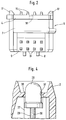
- a sealing lip 36 is injection molded in the area of the passage opening 37 of the diode 38 through the housing part 2 onto the housing part, as shown in more detail in FIG. 4. The sealing lip is moved upward when the upper housing part 2 is placed on the diode 28, so that it lies tightly against the lamp body of the diode 28.
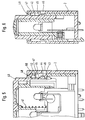
- FIGS. 5 and 6 Further measures for keeping away or removing moisture from the interior of the switch are shown in FIGS. 5 and 6 by means of a pressure switch, which can also be seated on the printed circuit board 4. However, the measures described here can also be used with other types of switches, such as the toggle switches described above or with rotary switches.
- the push button 40 can be pressed against the bias of the spring 41 in the housing.
- a housing side surface 43 slides on a key side surface 42.
- the housing wall 44 with the side surface 43 has a wiping edge 45 which is inclined outwards. The liquid wiped off the key side wall 42 thus flows off over the edge 45 and the outer surface of the side wall 44 and the outer side surface then passes into an outlet channel 46 through which the collected moisture is conducted out of the housing.
- a further improvement against the ingress of water can be achieved with the aid of the circumferential extension 60 attached to the obliquely running umbrella-like projection 48, which in connection with the projection 48 forms a channel which is open at the bottom.
- the screen In the pushed-out position of the button, the screen seals the inside of the switch against the ingress of moisture, in that it lies under a resilient pretension against an inward extension of the housing 2.
- the housing wall is shown consisting of two walls by an outer side wall of the housing part 2 being pushed over the inner side wall of the switch. However, this is not important for the present invention. Rather, the two housing walls pushed into one another can also be formed in one piece.
- the space 47 existing between the inner wall of the housing and the key side wall 42 is closed off by an umbrella-like projection 48 of the key, which also serves as a stop for the upward movement of the key in FIGS. 5 and 6 .
- the liquid which possibly penetrates from the top along the touch wall can be drained outward away from the button, so that, as can be seen from FIG. 6, it can run along the inner surface of the outer housing wall via the channel 46.
- measures taken to prevent the ingress of liquid into the interior of the housing but at the same time measures are also introduced which remove the moisture which may have penetrated from the interior of the housing.
- FIG. 7 and 8 show the inventive principle applied to a switch combination consisting of several switches.
- a single printed circuit board 4 is provided, on which the switches described above are applied as a switch combination.
- These are four switches 50, 51, 52, 53 in the form of toggle switches and a pressure switch 54.
- the toggle switches are used to open and close the four side windows of a vehicle, while the pressure switch 54 serves as a child lock and not only the rear door lock of secures inside, but at the same time prevents opening of the rear windows.
- Such use of a switch combination can serve as a console switch in a center console of a car.
- four of the four frames provided are equipped with contact rockers 20, one frame being provided for each switch.
- the frame 19 can also be equipped with two contact rockers, so that using a correspondingly small housing, double switches with small dimensions result, which can be installed below the windows in the door upholstery.
- the sealing measures described above are aimed in particular at this purpose.
Landscapes
- Push-Button Switches (AREA)
- Switch Cases, Indication, And Locking (AREA)
- Tumbler Switches (AREA)
Applications Claiming Priority (2)
| Application Number | Priority Date | Filing Date | Title |
|---|---|---|---|
| DE19541380 | 1995-11-07 | ||
| DE19541380A DE19541380A1 (de) | 1995-11-07 | 1995-11-07 | Schalter mit auf die Leiterplatte aufgerasteten Schaltmodulen |
Publications (3)
| Publication Number | Publication Date |
|---|---|
| EP0773568A2 true EP0773568A2 (fr) | 1997-05-14 |
| EP0773568A3 EP0773568A3 (fr) | 1998-07-22 |
| EP0773568B1 EP0773568B1 (fr) | 2004-10-27 |
Family
ID=7776777
Family Applications (1)
| Application Number | Title | Priority Date | Filing Date |
|---|---|---|---|
| EP96117607A Expired - Lifetime EP0773568B1 (fr) | 1995-11-07 | 1996-11-04 | Commutateur avec modules de commutation montés sur la carte de circuit imprimé |
Country Status (2)
| Country | Link |
|---|---|
| EP (1) | EP0773568B1 (fr) |
| DE (2) | DE19541380A1 (fr) |
Cited By (8)
| Publication number | Priority date | Publication date | Assignee | Title |
|---|---|---|---|---|
| DE19722674A1 (de) * | 1997-05-30 | 1998-12-03 | Abb Patent Gmbh | Wipptaster |
| DE19817900A1 (de) * | 1998-04-22 | 1999-10-28 | Itt Mfg Enterprises Inc | Betätigungsvorrichtung für einen Schalter |
| EP1037228A3 (fr) * | 1999-03-11 | 2001-07-18 | Alps Electric Co., Ltd. | Dispositif de commutation illuminé pour illumination stabilisée de la partie translucide d'un bouton |
| DE10056449A1 (de) * | 2000-11-14 | 2002-05-29 | Kostal Leopold Gmbh & Co Kg | Wippschalteranordnung |
| EP1526559A1 (fr) * | 2003-10-24 | 2005-04-27 | TRW Automotive U.S. LLC | Commutateur à bascule |
| EP1536443A1 (fr) * | 2003-11-26 | 2005-06-01 | Kabushiki Kaisha Tokai Rika Denki Seisakusho | Appareil interrupteur pour lève-vitre |
| CN103137369A (zh) * | 2011-11-24 | 2013-06-05 | 耐力株式会社 | 开关装置 |
| US11066091B2 (en) * | 2016-12-05 | 2021-07-20 | Valeo Schalter Und Sensoren Gmbh | Operating apparatus comprising rocker element for operating at least one electrical appliance, motor vehicle component comprising an operating apparatus, motor vehicle and method for operating an operating apparatus |
Families Citing this family (1)
| Publication number | Priority date | Publication date | Assignee | Title |
|---|---|---|---|---|
| DE19804453A1 (de) * | 1998-02-05 | 1999-08-12 | Itt Mfg Enterprises Inc | Schwimmend gelagerter Verbinder zum Verbinden elektrischer Baugruppen |
Family Cites Families (18)
| Publication number | Priority date | Publication date | Assignee | Title |
|---|---|---|---|---|
| GB1308692A (en) * | 1970-04-01 | 1973-02-21 | Sumlock Anita Electronics Ltd | Electrical switches |
| DE7130971U (de) * | 1971-08-12 | 1971-11-25 | Sachsse L | Schalteranordnung für gedruckte Schaltungen |
| DE2716042A1 (de) * | 1977-04-09 | 1978-10-19 | Kirsten Elektrotech | Elektrischer schalter, insbesondere armaturenbrettschalter fuer kraftfahrzeuge |
| US4210382A (en) * | 1979-05-23 | 1980-07-01 | Ford Motor Company | Electrical connector and housing |
| DE3103334A1 (de) * | 1981-01-31 | 1982-08-26 | Gebr. Berker GmbH & Co, 5885 Schalksmühle | Elektrischer geraete-einbauschalter |
| DE3240940A1 (de) * | 1982-11-05 | 1984-05-10 | Wilhelm Ruf KG, 8000 München | Taste zum schliessen elektrischer kontakte |
| DE3545879C2 (de) * | 1985-12-23 | 1995-11-30 | Asea Brown Boveri | Abgedichteter Drucktastenschalter, insb. in Schmalbauweise |
| DE3607181A1 (de) * | 1986-03-05 | 1987-09-10 | Preh Elektro Feinmechanik | Schalteranordnung |
| ATE44125T1 (de) * | 1987-02-07 | 1989-06-15 | Hans Weiss | Gehaeuse oder gehaeuseteil mit wenigstens einer taste eines elektrischen schalters. |
| DE8711882U1 (de) * | 1987-09-02 | 1987-10-22 | Preh, Elektrofeinmechanische Werke Jakob Preh Nachf. Gmbh & Co, 8740 Bad Neustadt | Fassung für eine Leuchtdiode |
| DE8810929U1 (de) * | 1988-08-30 | 1988-12-01 | BSG-Schalttechnik GmbH & Co KG, 7460 Balingen | Schalter zur Montage auf Schaltplatte |
| DE3930538A1 (de) * | 1989-09-13 | 1991-03-21 | Swf Auto Electric Gmbh | Elektrisches geraet, insbesondere elektrischer schalter |
| US5105059A (en) * | 1991-03-14 | 1992-04-14 | Carlingswitch, Inc. | Environmentally sealed switch construction |
| DE4218545A1 (de) * | 1992-06-05 | 1993-12-09 | Abb Patent Gmbh | Elektrisches Schaltgerät |
| DE9212062U1 (de) * | 1992-09-08 | 1992-10-29 | Abb Patent Gmbh, 68309 Mannheim | Wipptaster |
| US5414231A (en) * | 1993-03-15 | 1995-05-09 | Tokyo Denso Kabushiki Kaisha | Switch device |
| US5412166A (en) * | 1993-06-25 | 1995-05-02 | United Technologies Automotive, Inc. | Power window switch control apparatus |
| DE4326312A1 (de) * | 1993-08-05 | 1995-02-09 | Teves Gmbh Alfred | Kippschalter mit Anschlag zur Geräuschdämpfung |
-
1995
- 1995-11-07 DE DE19541380A patent/DE19541380A1/de not_active Withdrawn
-
1996
- 1996-11-04 EP EP96117607A patent/EP0773568B1/fr not_active Expired - Lifetime
- 1996-11-04 DE DE59611127T patent/DE59611127D1/de not_active Expired - Lifetime
Non-Patent Citations (1)
| Title |
|---|
| None |
Cited By (14)
| Publication number | Priority date | Publication date | Assignee | Title |
|---|---|---|---|---|
| EP0887821A3 (fr) * | 1997-05-30 | 1999-06-02 | ABBPATENT GmbH | Touche basculante |
| DE19722674A1 (de) * | 1997-05-30 | 1998-12-03 | Abb Patent Gmbh | Wipptaster |
| DE19817900A1 (de) * | 1998-04-22 | 1999-10-28 | Itt Mfg Enterprises Inc | Betätigungsvorrichtung für einen Schalter |
| DE19817900B4 (de) * | 1998-04-22 | 2008-07-10 | Valeo Schalter Und Sensoren Gmbh | Betätigungsvorrichtung für einen Schalter |
| EP1037228A3 (fr) * | 1999-03-11 | 2001-07-18 | Alps Electric Co., Ltd. | Dispositif de commutation illuminé pour illumination stabilisée de la partie translucide d'un bouton |
| US6388220B1 (en) | 1999-03-11 | 2002-05-14 | Alps Electronic Co., Ltd. | Illuminated switching device for stabilized illumination to translucent portion of knob |
| DE10056449B4 (de) * | 2000-11-14 | 2005-07-28 | Leopold Kostal Gmbh & Co. Kg | Wippschalteranordnung |
| DE10056449A1 (de) * | 2000-11-14 | 2002-05-29 | Kostal Leopold Gmbh & Co Kg | Wippschalteranordnung |
| EP1526559A1 (fr) * | 2003-10-24 | 2005-04-27 | TRW Automotive U.S. LLC | Commutateur à bascule |
| US6974918B2 (en) | 2003-10-24 | 2005-12-13 | Trw Automotive U.S. Llc | Rocker switch |
| US7102092B2 (en) | 2003-11-26 | 2006-09-05 | Kabushiki Kaisha Tokai Rika Denki Seisakusho | Power window switch apparatus |
| EP1536443A1 (fr) * | 2003-11-26 | 2005-06-01 | Kabushiki Kaisha Tokai Rika Denki Seisakusho | Appareil interrupteur pour lève-vitre |
| CN103137369A (zh) * | 2011-11-24 | 2013-06-05 | 耐力株式会社 | 开关装置 |
| US11066091B2 (en) * | 2016-12-05 | 2021-07-20 | Valeo Schalter Und Sensoren Gmbh | Operating apparatus comprising rocker element for operating at least one electrical appliance, motor vehicle component comprising an operating apparatus, motor vehicle and method for operating an operating apparatus |
Also Published As
| Publication number | Publication date |
|---|---|
| EP0773568B1 (fr) | 2004-10-27 |
| EP0773568A3 (fr) | 1998-07-22 |
| DE19541380A1 (de) | 1997-05-15 |
| DE59611127D1 (de) | 2004-12-02 |
Similar Documents
| Publication | Publication Date | Title |
|---|---|---|
| DE19746621C2 (de) | Schalteranordnung | |
| DE2248489A1 (de) | Stecker zum verbinden elektrischer leitungen | |
| EP0356706B1 (fr) | Interrupteur pour le montage sur une plaque à circuit im primé | |
| EP3107111B1 (fr) | Partie de socle pour un dispositif de commutateur modulaire electrique | |
| EP0773568B1 (fr) | Commutateur avec modules de commutation montés sur la carte de circuit imprimé | |
| EP0222181A1 (fr) | Disjoncteur de surintensité | |
| EP0122465A2 (fr) | Commutateur électrique ou bouton poussoir contenant deux bascules à grande surface | |
| DE4010906C2 (de) | Buchse mit Schalter | |
| EP0235350B1 (fr) | Interrupteur, en particulier pour véhicule | |
| DE19746085C2 (de) | Schalterverbindungsanordnung | |
| DE1465705B1 (de) | Elektrischer Schnappschalter mit Drueckerhebel | |
| DE3534364A1 (de) | Elektrische verbinderanordnung zur verwendung auf begrenztem raum | |
| DE4018978C2 (de) | Schiebeschalter | |
| DE2422021A1 (de) | Elektrische schalter | |
| EP0221201A1 (fr) | Boîtier pour circuits électriques et électroniques | |
| DE2951327A1 (de) | Hermetisch dichte schaltervorrichtung | |
| EP0976310B1 (fr) | Appareil electrique a deux capots de boitier identiques | |
| DE3620416C2 (fr) | ||
| DE29515351U1 (de) | Folientastatur | |
| DE69402167T2 (de) | Mehrfacher Sockel für Steckdose | |
| DE3142070A1 (de) | Elektrischer installationsschalter | |
| DE4242962C2 (de) | Elektrischer Installationsschalter | |
| DE4015619C2 (fr) | ||
| EP0763247B1 (fr) | Interrupteur a action brusque, a deplacement rectiligne du contact et systeme d'interrupteur associe | |
| EP0451248B1 (fr) | Interrupteur a poussoir electrique, notamment interrupteur d'avertisseur lumineux pour vehicules a moteur |
Legal Events
| Date | Code | Title | Description |
|---|---|---|---|
| PUAI | Public reference made under article 153(3) epc to a published international application that has entered the european phase |
Free format text: ORIGINAL CODE: 0009012 |
|
| AK | Designated contracting states |
Kind code of ref document: A2 Designated state(s): DE ES FR GB IT |
|
| PUAL | Search report despatched |
Free format text: ORIGINAL CODE: 0009013 |
|
| AK | Designated contracting states |
Kind code of ref document: A3 Designated state(s): DE ES FR GB IT |
|
| 17P | Request for examination filed |
Effective date: 19990122 |
|
| RAP1 | Party data changed (applicant data changed or rights of an application transferred) |
Owner name: VALEO SCHALTER UND SENSOREN GMBH |
|
| 17Q | First examination report despatched |
Effective date: 20030520 |
|
| GRAP | Despatch of communication of intention to grant a patent |
Free format text: ORIGINAL CODE: EPIDOSNIGR1 |
|
| GRAS | Grant fee paid |
Free format text: ORIGINAL CODE: EPIDOSNIGR3 |
|
| GRAA | (expected) grant |
Free format text: ORIGINAL CODE: 0009210 |
|
| AK | Designated contracting states |
Kind code of ref document: B1 Designated state(s): DE ES FR GB IT |
|
| PG25 | Lapsed in a contracting state [announced via postgrant information from national office to epo] |
Ref country code: IT Free format text: LAPSE BECAUSE OF FAILURE TO SUBMIT A TRANSLATION OF THE DESCRIPTION OR TO PAY THE FEE WITHIN THE PRESCRIBED TIME-LIMIT;WARNING: LAPSES OF ITALIAN PATENTS WITH EFFECTIVE DATE BEFORE 2007 MAY HAVE OCCURRED AT ANY TIME BEFORE 2007. THE CORRECT EFFECTIVE DATE MAY BE DIFFERENT FROM THE ONE RECORDED. Effective date: 20041027 |
|
| REG | Reference to a national code |
Ref country code: GB Ref legal event code: FG4D Free format text: NOT ENGLISH |
|
| GBT | Gb: translation of ep patent filed (gb section 77(6)(a)/1977) |
Effective date: 20041027 |
|
| REF | Corresponds to: |
Ref document number: 59611127 Country of ref document: DE Date of ref document: 20041202 Kind code of ref document: P |
|
| PG25 | Lapsed in a contracting state [announced via postgrant information from national office to epo] |
Ref country code: ES Free format text: LAPSE BECAUSE OF FAILURE TO SUBMIT A TRANSLATION OF THE DESCRIPTION OR TO PAY THE FEE WITHIN THE PRESCRIBED TIME-LIMIT Effective date: 20050207 |
|
| PLBE | No opposition filed within time limit |
Free format text: ORIGINAL CODE: 0009261 |
|
| STAA | Information on the status of an ep patent application or granted ep patent |
Free format text: STATUS: NO OPPOSITION FILED WITHIN TIME LIMIT |
|
| ET | Fr: translation filed | ||
| 26N | No opposition filed |
Effective date: 20050728 |
|
| PGFP | Annual fee paid to national office [announced via postgrant information from national office to epo] |
Ref country code: GB Payment date: 20081107 Year of fee payment: 13 |
|
| GBPC | Gb: european patent ceased through non-payment of renewal fee |
Effective date: 20091104 |
|
| PG25 | Lapsed in a contracting state [announced via postgrant information from national office to epo] |
Ref country code: GB Free format text: LAPSE BECAUSE OF NON-PAYMENT OF DUE FEES Effective date: 20091104 |
|
| REG | Reference to a national code |
Ref country code: FR Ref legal event code: PLFP Year of fee payment: 20 |
|
| PGFP | Annual fee paid to national office [announced via postgrant information from national office to epo] |
Ref country code: DE Payment date: 20151109 Year of fee payment: 20 |
|
| PGFP | Annual fee paid to national office [announced via postgrant information from national office to epo] |
Ref country code: FR Payment date: 20151130 Year of fee payment: 20 |
|
| REG | Reference to a national code |
Ref country code: DE Ref legal event code: R071 Ref document number: 59611127 Country of ref document: DE |