EP0774802A2 - Elektrischer Verbinder mit internem elastischen Teil - Google Patents
Elektrischer Verbinder mit internem elastischen Teil Download PDFInfo
- Publication number
- EP0774802A2 EP0774802A2 EP96118137A EP96118137A EP0774802A2 EP 0774802 A2 EP0774802 A2 EP 0774802A2 EP 96118137 A EP96118137 A EP 96118137A EP 96118137 A EP96118137 A EP 96118137A EP 0774802 A2 EP0774802 A2 EP 0774802A2
- Authority
- EP
- European Patent Office
- Prior art keywords
- housing
- cam
- arm
- female
- electrical connector
- Prior art date
- Legal status (The legal status is an assumption and is not a legal conclusion. Google has not performed a legal analysis and makes no representation as to the accuracy of the status listed.)
- Granted
Links
- 238000003780 insertion Methods 0.000 claims description 9
- 230000037431 insertion Effects 0.000 claims description 9
- 230000000295 complement effect Effects 0.000 abstract 1
- 238000005452 bending Methods 0.000 description 2
- 238000000034 method Methods 0.000 description 2
- 229910000639 Spring steel Inorganic materials 0.000 description 1
- 238000010276 construction Methods 0.000 description 1
- 238000012856 packing Methods 0.000 description 1
Images


Classifications
-
- H—ELECTRICITY
- H01—ELECTRIC ELEMENTS
- H01R—ELECTRICALLY-CONDUCTIVE CONNECTIONS; STRUCTURAL ASSOCIATIONS OF A PLURALITY OF MUTUALLY-INSULATED ELECTRICAL CONNECTING ELEMENTS; COUPLING DEVICES; CURRENT COLLECTORS
- H01R13/00—Details of coupling devices of the kinds covered by groups H01R12/70 or H01R24/00 - H01R33/00
- H01R13/62—Means for facilitating engagement or disengagement of coupling parts or for holding them in engagement
- H01R13/627—Snap or like fastening
-
- H—ELECTRICITY
- H01—ELECTRIC ELEMENTS
- H01R—ELECTRICALLY-CONDUCTIVE CONNECTIONS; STRUCTURAL ASSOCIATIONS OF A PLURALITY OF MUTUALLY-INSULATED ELECTRICAL CONNECTING ELEMENTS; COUPLING DEVICES; CURRENT COLLECTORS
- H01R13/00—Details of coupling devices of the kinds covered by groups H01R12/70 or H01R24/00 - H01R33/00
- H01R13/64—Means for preventing incorrect coupling
- H01R13/641—Means for preventing incorrect coupling by indicating incorrect coupling; by indicating correct or full engagement
Definitions
- the present Invention relates to an electrical connector, in particular, one which prevents incomplete fitting and minimizes the risk of entanglement during packing and shipping.
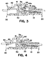
- connector 1 comprises male housing 2 and female housing 3 which are adapted to fit together, and pivoting member 4 comprising cam 4a attached to male housing 2 and sliding against female housing 3.
- pivoting member 4 comprising cam 4a attached to male housing 2 and sliding against female housing 3.
- the side toward the interface between the housings is referred to as the front.
- Pivoting member 4 is formed as a square, C-shaped hood. Pivot holes 4b, disposed on the rear of member 4, are attached to supporting shafts 2a which project from approximately the center of the two sides of male housing 2.
- Resilient member 5 serves to press pivoting member 4 against the upper surface of the front of male housing 2.
- elastic member 5 is substantially U-shaped and is formed by bending a plate spring to form free ends 5a, 5b. The open side of the U is turned toward the front. Free end 5a is fixed to male housing 2, and the other free end 5b presses against pivoting member 4 from the outside.
- the object of the present Invention is to overcome the drawbacks of the prior art described above and, in particular, to provide a connector that is easy to handle and whose resilient member does not undesirably engage parts of other connectors.
- a pivoting member urged by a resilient member is disposed on a first of two mutually fittable housings.
- a second housing is fitted to the front of the first housing and the two housings are brought to a fitting position by rotating the pivoting member so that it overcomes the force of the resilient member.
- the pivoting member comprises a bearing point disposed further toward the rear than the pivot, and the resilient member is disposed between the bearing point and the first housing so that it urges the bearing point upward.
- the resilient member is in a U-shape, and the bend of the U-shape is located on the pivot side.
- the two parallel legs of the U are pressed against the bearing point and the first housing so that the bearing point is pushed outward.
- the second housing when the second housing is fitted to the front of the first housing, the second housing causes the pivoting member to pivot in opposition to the elastic force exerted by the resilient member. If, during this fitting process, the insertion of the second housing is stopped before the maximum elastic force is overcome, the connectors would be in a partially fitted state, and the elastic force of the resilient member would reject the second housing. Conversely, if insertion of the second housing is stopped after the maximum elastic force is overcome, the housing would be drawn in by the elastic force of the resilient member, thus bringing the connector to a complete fit. In either case, an incomplete fit is avoided.
- the housings can be disengaged without requiring the use of both hands, as in conventional devices.
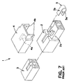
- Connector 10 comprises a male housing 20 and a female housing 30, which are adapted to fit together.
- Member 40 is pivotally attached to female housing 30.
- Male housing 20 can hold two male terminals 11. Toward the front is male hood 21 which fits into female housing 30. A flexible shorting piece 13 is cantilevered inside male housing 20. The free end thereof is in contact with male terminal 11 so that the two are shorted. Shorted piece 13 can be flexed by disengagement piece 33 so that it no longer contacts male terminal 11; in other words, the degree of insertion of the housings in connector 10 can be determined by whether male terminals 11 are continuous.
- Female housing 30 holds female terminal 12, which is adapted to electrically connect with male terminal 11.
- Cylindrical female hood 31 having a raised portion toward the front is disposed on female housing 30.
- Body 32 projects from the far inside wall of female hood 31. The gap between female hood 31 and body 32 allows male hood 21 to be inserted.
- Disengagement piece 33 projects from the front surface of body 32; when fitting is complete, it deflects shorting piece 13 so that the short between male terminals 11 is disengaged.
- Pivoting member 40 carries a raised portion corresponding to the raised portion on the upper surface wall of female housing 30. Arm 41 formed by the front side of the raised portion comes into contact with upper surface 31a of female hood 31. Operating portion 42 enters rotation groove 34 formed toward the rear of female housing 30. Pivoting member 40 comprises support 43 which extends toward the two sides at roughly the center point of member 40 and bends downward. Rotation holes 43a, on the ends of support 43, engage shafts 35, which project from the sides of female housing 30. When member 40 is attached to female housing 30, arm 41 is disposed between protecting walls 31b, at the side edges of upper surface 31a, and operating portion 42 is in rotation groove 34. Neither operating portion 42 nor arm 41 projects externally. Furthermore, support 43 is located at the raised portion so that the part of it which does project outward is kept to a minimum.
- cam 44 is on the surface of arm 41 which comes into contact with female hood 31.
- Cam 44 extends through hole 31a1 and thus projects into female hood 31.
- Incline 44a slopes toward the front and the rear and slides against male housing 20 when the housing is inserted into female hood 31.
- Groove 21a is on the part of male hood 21 facing cam 44 so that there is no obstruction thereof.
- Actuator 22 is also disposed on male hood 22 so as to prevent obstruction.
- Incline 22a raised at the center, is on the upper surface of actuator 22 to slide against incline 44a.
- Resilient member 50 is formed by bending a spring steel plate into a U-shape.
- Resilient member 50 comprises bend 52 connecting two free ends 51a and 51b.
- Free end 51a is about the same length as operating portion 42.
- Bend 52 is positioned toward the front and free end 51a is disposed against the lower surface of operating portion 42.
- Free end 51b is slightly shorter than end 51a, and is in contact with bottom surface 34a of rotation groove 34. The end of free end 51a is fixed by engagement piece 42b on the rear of operating portion 42.
- the gap between free ends 51a and 51b is greater than the gap between bottom surface 34a and operating portion 42. This provides a preloading force applied to arm 41 and presses it against female hood 31, thereby avoiding looseness.
- pivoting member 40 includes cam 44 projecting inside female hood 31 of female housing 30.
- Cam 44 is in contact with female hood 31 due to the pressure of resilient member 50.
- the opening of male hood 21 is oriented to face female hood 31 and male hood 21 is inserted into female hood 31. This causes the front incline of incline 22a to contact the front incline of incline 44a.
- cam 44 when male housing 20 is pressed in further, the sliding of the front incline causes cam 44 to be lifted.
- This causes operating portion 42 to pivot downward and compresses resilient member 50.
- a strong elastic force is created which causes male housing 20 to be pushed out.
- male housing 20 is pushed out of female housing 30, thus preventing an incomplete fit.
- Male housing 20 is inserted all the way into female housing 30 while the rear inclines of incline 44a and incline 22a slide against each other.
- cam 44 goes past actuator 22 and the elastic force of resilient member 50 causes it to return to its original position, so that cam 44 projects into female hood 31 again.
- perpendicular surface 44b would be in contact with rear surface 22b of actuator 22, thus locking the housing together.
- the housings can be disengaged by pressing operating portion 42 inward, thereby moving cam shaped projection 44 out of female hood 31. This allows male housing 20 to be easily removed.
- Resilient member 50 which prevents incomplete assembly, does not project outward since it is attached between pivoting member 40 and female housing 30. Also, when no fitting operation is being performed, member 40 does not project outward and is entirely located in the prescribed space in female housing 30.
- this configuration avoids the problem of the prior art wherein handling is made difficult by the fact that the projecting portions of resilient members and pivoting members can catch each other when a plurality of connectors, especially if harnesses are attached, are being shipped in a single container.
Landscapes
- Details Of Connecting Devices For Male And Female Coupling (AREA)
- Connector Housings Or Holding Contact Members (AREA)
Applications Claiming Priority (2)
| Application Number | Priority Date | Filing Date | Title |
|---|---|---|---|
| JP321074/95 | 1995-11-14 | ||
| JP7321074A JPH09139251A (ja) | 1995-11-14 | 1995-11-14 | コネクタ |
Publications (3)
| Publication Number | Publication Date |
|---|---|
| EP0774802A2 true EP0774802A2 (de) | 1997-05-21 |
| EP0774802A3 EP0774802A3 (de) | 1998-04-08 |
| EP0774802B1 EP0774802B1 (de) | 2008-12-31 |
Family
ID=18128523
Family Applications (1)
| Application Number | Title | Priority Date | Filing Date |
|---|---|---|---|
| EP96118137A Expired - Lifetime EP0774802B1 (de) | 1995-11-14 | 1996-11-12 | Elektrischer Verbinder mit internem elastischen Teil |
Country Status (4)
| Country | Link |
|---|---|
| US (1) | US5782647A (de) |
| EP (1) | EP0774802B1 (de) |
| JP (1) | JPH09139251A (de) |
| DE (1) | DE69637796D1 (de) |
Families Citing this family (18)
| Publication number | Priority date | Publication date | Assignee | Title |
|---|---|---|---|---|
| JP3341819B2 (ja) * | 1997-10-09 | 2002-11-05 | 矢崎総業株式会社 | 端子固定具付コネクタ |
| US6007362A (en) * | 1997-12-09 | 1999-12-28 | The Whitaker Corporation | Electrical connector assembly for a refrigerator door |
| JP3467185B2 (ja) * | 1998-04-08 | 2003-11-17 | 矢崎総業株式会社 | コネクタのロック機構 |
| US6460848B1 (en) | 1999-04-21 | 2002-10-08 | Mindplay Llc | Method and apparatus for monitoring casinos and gaming |
| AUPS315002A0 (en) * | 2002-06-25 | 2002-07-18 | Resmed Limited | Method & apparatus for control of appliance coupler retention and withdrawal forces |
| JP4089589B2 (ja) * | 2003-10-30 | 2008-05-28 | 住友電装株式会社 | コネクタ |
| US8109883B2 (en) | 2006-09-28 | 2012-02-07 | Tyco Healthcare Group Lp | Cable monitoring apparatus |
| US8668651B2 (en) | 2006-12-05 | 2014-03-11 | Covidien Lp | ECG lead set and ECG adapter system |
| CA2646037C (en) | 2007-12-11 | 2017-11-28 | Tyco Healthcare Group Lp | Ecg electrode connector |
| USD737979S1 (en) | 2008-12-09 | 2015-09-01 | Covidien Lp | ECG electrode connector |
| US8694080B2 (en) | 2009-10-21 | 2014-04-08 | Covidien Lp | ECG lead system |
| CA2746944C (en) | 2010-07-29 | 2018-09-25 | Tyco Healthcare Group Lp | Ecg adapter system and method |
| ES2762190T3 (es) | 2011-07-22 | 2020-05-22 | Kpr Us Llc | Conector de electrodo ECG |
| US8634901B2 (en) | 2011-09-30 | 2014-01-21 | Covidien Lp | ECG leadwire system with noise suppression and related methods |
| USD771818S1 (en) | 2013-03-15 | 2016-11-15 | Covidien Lp | ECG electrode connector |
| US9408546B2 (en) | 2013-03-15 | 2016-08-09 | Covidien Lp | Radiolucent ECG electrode system |
| DK2967396T3 (da) | 2013-03-15 | 2019-05-20 | Kpr Us Llc | Elektrodekonnektor med et ledende element |
| DE102021127033B3 (de) * | 2021-10-19 | 2022-11-10 | Md Elektronik Gmbh | Steckverbinderanordnung zum verbinden von signalleitern |
Citations (1)
| Publication number | Priority date | Publication date | Assignee | Title |
|---|---|---|---|---|
| JPH07211392A (ja) | 1994-01-21 | 1995-08-11 | Sumitomo Wiring Syst Ltd | コネクタ |
Family Cites Families (6)
| Publication number | Priority date | Publication date | Assignee | Title |
|---|---|---|---|---|
| NL8403691A (nl) * | 1984-12-05 | 1986-07-01 | Philips Nv | Optische verbindingsinrichting. |
| DE3740580A1 (de) * | 1987-11-30 | 1989-06-08 | Grote & Hartmann | Elektrischer steckverbinder |
| US5376017A (en) * | 1992-09-29 | 1994-12-27 | Sumitomo Wiring Systems, Ltd. | Connector |
| US5310358A (en) * | 1992-12-22 | 1994-05-10 | The Whitaker Corporation | Computer docking system |
| JP2970347B2 (ja) * | 1993-09-28 | 1999-11-02 | 住友電装株式会社 | コネクタ |
| DE69415786T2 (de) * | 1993-12-06 | 1999-08-05 | Sumitomo Wiring Systems, Ltd., Yokkaichi, Mie | Verbinder mit Verriegelungserkennung |
-
1995
- 1995-11-14 JP JP7321074A patent/JPH09139251A/ja active Pending
-
1996
- 1996-11-12 US US08/747,554 patent/US5782647A/en not_active Expired - Lifetime
- 1996-11-12 DE DE69637796T patent/DE69637796D1/de not_active Expired - Lifetime
- 1996-11-12 EP EP96118137A patent/EP0774802B1/de not_active Expired - Lifetime
Patent Citations (1)
| Publication number | Priority date | Publication date | Assignee | Title |
|---|---|---|---|---|
| JPH07211392A (ja) | 1994-01-21 | 1995-08-11 | Sumitomo Wiring Syst Ltd | コネクタ |
Also Published As
| Publication number | Publication date |
|---|---|
| EP0774802B1 (de) | 2008-12-31 |
| JPH09139251A (ja) | 1997-05-27 |
| DE69637796D1 (de) | 2009-02-12 |
| EP0774802A3 (de) | 1998-04-08 |
| US5782647A (en) | 1998-07-21 |
Similar Documents
| Publication | Publication Date | Title |
|---|---|---|
| US5782647A (en) | Electrical connector with internal resilient member | |
| JP3250787B2 (ja) | 電気コネクタのロック装置 | |
| US5938470A (en) | Half-fitting prevention connector | |
| EP0975065A2 (de) | Verbinder | |
| EP1049213B1 (de) | Verbindungsvorrichtung für Steckverbinder | |
| US5104330A (en) | Electric connector | |
| US10547142B1 (en) | Latch assembly for a plug connector | |
| EP0727847A2 (de) | Handhebel betätigter Verbinder | |
| JP2001160457A (ja) | 半嵌合防止コネクタ | |
| JP3472686B2 (ja) | スライド嵌合型コネクタ | |
| US6027364A (en) | Connector fitting construction with side ribs and corresponding side rib-receiving portions | |
| US7300300B2 (en) | Connector system with improved unplugging functionality | |
| JPH1050408A (ja) | コネクタ嵌合構造 | |
| US20010023154A1 (en) | Connector fitting structure | |
| JPH09185974A (ja) | コネクタの嵌合解除機構 | |
| US6341973B1 (en) | Half-fitting prevention connector for detecting and preventing half-fitted condition | |
| US5957710A (en) | Lif connector | |
| JP3741351B2 (ja) | 半嵌合防止コネクタ | |
| US6250945B1 (en) | Half-fitting prevention connector | |
| TW299511B (de) | ||
| US6113413A (en) | Latchable electrical connector | |
| JPH09324805A (ja) | 樹脂成形品のロック装置 | |
| JP4764573B2 (ja) | ケーブルコネクタ | |
| JP3467385B2 (ja) | スライド嵌合型コネクタ | |
| JP3467388B2 (ja) | スライド嵌合型コネクタ |
Legal Events
| Date | Code | Title | Description |
|---|---|---|---|
| PUAI | Public reference made under article 153(3) epc to a published international application that has entered the european phase |
Free format text: ORIGINAL CODE: 0009012 |
|
| AK | Designated contracting states |
Kind code of ref document: A2 Designated state(s): DE FR GB |
|
| 17P | Request for examination filed |
Effective date: 19970526 |
|
| PUAL | Search report despatched |
Free format text: ORIGINAL CODE: 0009013 |
|
| AK | Designated contracting states |
Kind code of ref document: A3 Designated state(s): DE FR GB |
|
| 17Q | First examination report despatched |
Effective date: 19991008 |
|
| APBR | Date of receipt of statement of grounds of appeal recorded |
Free format text: ORIGINAL CODE: EPIDOSNNOA3E |
|
| APBT | Appeal procedure closed |
Free format text: ORIGINAL CODE: EPIDOSNNOA9E |
|
| APAF | Appeal reference modified |
Free format text: ORIGINAL CODE: EPIDOSCREFNE |
|
| GRAP | Despatch of communication of intention to grant a patent |
Free format text: ORIGINAL CODE: EPIDOSNIGR1 |
|
| GRAS | Grant fee paid |
Free format text: ORIGINAL CODE: EPIDOSNIGR3 |
|
| GRAA | (expected) grant |
Free format text: ORIGINAL CODE: 0009210 |
|
| AK | Designated contracting states |
Kind code of ref document: B1 Designated state(s): DE FR GB |
|
| REG | Reference to a national code |
Ref country code: GB Ref legal event code: FG4D |
|
| REF | Corresponds to: |
Ref document number: 69637796 Country of ref document: DE Date of ref document: 20090212 Kind code of ref document: P |
|
| PLBE | No opposition filed within time limit |
Free format text: ORIGINAL CODE: 0009261 |
|
| STAA | Information on the status of an ep patent application or granted ep patent |
Free format text: STATUS: NO OPPOSITION FILED WITHIN TIME LIMIT |
|
| 26N | No opposition filed |
Effective date: 20091001 |
|
| REG | Reference to a national code |
Ref country code: FR Ref legal event code: PLFP Year of fee payment: 20 |
|
| PGFP | Annual fee paid to national office [announced via postgrant information from national office to epo] |
Ref country code: DE Payment date: 20151103 Year of fee payment: 20 Ref country code: GB Payment date: 20151111 Year of fee payment: 20 |
|
| PGFP | Annual fee paid to national office [announced via postgrant information from national office to epo] |
Ref country code: FR Payment date: 20151008 Year of fee payment: 20 |
|
| REG | Reference to a national code |
Ref country code: DE Ref legal event code: R071 Ref document number: 69637796 Country of ref document: DE |
|
| REG | Reference to a national code |
Ref country code: GB Ref legal event code: PE20 Expiry date: 20161111 |
|
| PG25 | Lapsed in a contracting state [announced via postgrant information from national office to epo] |
Ref country code: GB Free format text: LAPSE BECAUSE OF EXPIRATION OF PROTECTION Effective date: 20161111 |