EP0775656A2 - Margeur et procédé de séparation des feuilles - Google Patents
Margeur et procédé de séparation des feuilles Download PDFInfo
- Publication number
- EP0775656A2 EP0775656A2 EP96118618A EP96118618A EP0775656A2 EP 0775656 A2 EP0775656 A2 EP 0775656A2 EP 96118618 A EP96118618 A EP 96118618A EP 96118618 A EP96118618 A EP 96118618A EP 0775656 A2 EP0775656 A2 EP 0775656A2
- Authority
- EP
- European Patent Office
- Prior art keywords
- sheet
- stack
- uppermost
- sheet stack
- sheets
- Prior art date
- Legal status (The legal status is an assumption and is not a legal conclusion. Google has not performed a legal analysis and makes no representation as to the accuracy of the status listed.)
- Granted
Links
- 238000000034 method Methods 0.000 title claims description 9
- 239000000853 adhesive Substances 0.000 claims abstract description 24
- 230000001070 adhesive effect Effects 0.000 claims abstract description 24
- 238000007639 printing Methods 0.000 claims description 24
- 238000007664 blowing Methods 0.000 description 7
- 238000000926 separation method Methods 0.000 description 5
- 230000000284 resting effect Effects 0.000 description 3
- 230000001133 acceleration Effects 0.000 description 2
- 230000006978 adaptation Effects 0.000 description 1
- 230000000694 effects Effects 0.000 description 1
- 239000002184 metal Substances 0.000 description 1
- 238000007645 offset printing Methods 0.000 description 1
- 230000000737 periodic effect Effects 0.000 description 1
- 230000000717 retained effect Effects 0.000 description 1
- 239000000758 substrate Substances 0.000 description 1
Images




Classifications
-
- B—PERFORMING OPERATIONS; TRANSPORTING
- B65—CONVEYING; PACKING; STORING; HANDLING THIN OR FILAMENTARY MATERIAL
- B65H—HANDLING THIN OR FILAMENTARY MATERIAL, e.g. SHEETS, WEBS, CABLES
- B65H3/00—Separating articles from piles
- B65H3/32—Separating articles from piles by elements, e.g. fingers, plates, rollers, inserted or traversed between articles to be separated and remainder of the pile
-
- B—PERFORMING OPERATIONS; TRANSPORTING
- B65—CONVEYING; PACKING; STORING; HANDLING THIN OR FILAMENTARY MATERIAL
- B65H—HANDLING THIN OR FILAMENTARY MATERIAL, e.g. SHEETS, WEBS, CABLES
- B65H1/00—Supports or magazines for piles from which articles are to be separated
- B65H1/04—Supports or magazines for piles from which articles are to be separated adapted to support articles substantially horizontally, e.g. for separation from top of pile
-
- B—PERFORMING OPERATIONS; TRANSPORTING
- B65—CONVEYING; PACKING; STORING; HANDLING THIN OR FILAMENTARY MATERIAL
- B65H—HANDLING THIN OR FILAMENTARY MATERIAL, e.g. SHEETS, WEBS, CABLES
- B65H3/00—Separating articles from piles
- B65H3/02—Separating articles from piles using friction forces between articles and separator
- B65H3/06—Rollers or like rotary separators
-
- B—PERFORMING OPERATIONS; TRANSPORTING
- B65—CONVEYING; PACKING; STORING; HANDLING THIN OR FILAMENTARY MATERIAL
- B65H—HANDLING THIN OR FILAMENTARY MATERIAL, e.g. SHEETS, WEBS, CABLES
- B65H3/00—Separating articles from piles
- B65H3/46—Supplementary devices or measures to assist separation or prevent double feed
-
- B—PERFORMING OPERATIONS; TRANSPORTING
- B65—CONVEYING; PACKING; STORING; HANDLING THIN OR FILAMENTARY MATERIAL
- B65H—HANDLING THIN OR FILAMENTARY MATERIAL, e.g. SHEETS, WEBS, CABLES
- B65H2801/00—Application field
- B65H2801/03—Image reproduction devices
- B65H2801/21—Industrial-size printers, e.g. rotary printing press
Definitions
- the feeder of a sheet-fed printing press has the task of separating the sheets which have been precisely pre-stacked on a sheet support plate and then feeding them to the printing press in succession.
- the top sheet of the stack is lifted pneumatically by several suction cups attached to a rod in the front edge and then taken over by feed grippers or transport rollers. These guide the sheet individually to the press.
- the suction power By adjusting the suction power, by changing the tilting of the suction rod and by blowing air against the front edge of the stack, the single sheet feeder can be adapted to different paper thicknesses and paper qualities. As soon as the separated sheet has run into the machine, a new sheet can be separated. Therefore, with a single sheet feeder, the separating process must take place very quickly in order to achieve the desired machine speed.
- scale feeders are used, in which the sheets are separated by a suction head on the rear edge of the stack.
- a shed feeder has various pneumatic separating and drag suction devices that remove the top sheet and then feed it continuously to the feed table.
- scraper brushes, scraper plates and sheet hold-down are attached, which have the task of ensuring a trouble-free separation and ensure a smooth, straight transport of the sheets that are overlapped on a system table.
- each sheet is aligned precisely. Both the blowing and suction air as well as the other aids mentioned must be set exactly by the printer to the respective substrate.
- suction or blowing air is therefore required, and the higher the working speed, the more and the more powerful suction and blowing devices are required, with a correspondingly high air consumption.
- the suction and blowing devices cause considerable noise, and the periodic switching on and off of the air flows and the movement of the suction heads in the machine cycle lead to vibrations that are difficult to control.
- the invention has for its object to provide a sheet feeder and a method for sheet separation, which have a high working speed and reduced effort for suction and blowing devices and reduced air consumption.
- the sheet stack resting on a sheet support plate is bulged, preferably by the sheet support plate not being made flat.
- a concave shape of the stack of sheets, at least in the upper region, can alternatively be used e.g. B. also achieve that attack on the sides of a sheet stack lying flat drivers, which raise it partially. It is sufficient if the curvature is created on the machine side or on the side of the sheet stack facing away from the machine. If a convex curvature is desired, the curvature which a stack of sheets often has on its own can be used under certain circumstances.
- a plurality of adhesive elements press on the uppermost sheet, which are preferably arranged in the vicinity of the lateral sheet edges and have the adhesive surfaces which touch the sheet. In the case of a convex curvature, the adhesive elements or their adhesive surfaces are then moved towards one another. As a result, the uppermost sheet is partially raised from the sheet stack, so that a space is created between the uppermost sheet and the rest of the sheet stack.
- the adhesive surfaces are moved away from each other so that the top sheet is stretched. Stretching the sheet has the advantage that even thin papers can be separated safely.
- the dimensions of the resulting space are particularly well defined. This is advantageous if the resulting space is used to completely detach the sheet from the sheet stack and feed it to the printing press.
- z. B. grippers are provided which capture the leading edge of the sheet. The grippers pull the top sheet from the sheet stack, the remaining sheets being held back by a stop, and transfer it to the printing press. Because the adhesive elements only the top sheet partially lifted off the sheet stack, its position is precisely defined at the moment it is gripped. Therefore, the transfer can take place without a stopover, e.g. B. on transport rollers that convey the sheet in register in one go into the printing press. This smoothes the movement and the machine speed can be increased.
- the sheet stack is arched not in the front but in its rear area.
- the adhesive elements lift the uppermost sheet from the stack in its rear area, and one or more touch fingers can be inserted into the resulting space to hold the remaining sheets. This can be done on the back of the sheet stack and / or in the back of its sides.
- rotating friction wheels can be used for transporting the top sheet to the printing press.
- the finger or fingers can be released, the next sheet can be lifted with the aid of the adhesive elements and the finger or fingers can be brought back into position to feed the next sheet.
- the sheets can thus be fed to the printing press in close succession or even staggered. Nevertheless, there is enough time for the moving components to take up their various positions. Therefore, the sequence of movements can be designed so that only very slight accelerations of the components occur. As a result, the moving components and their drives can be dimensioned weaker and vibrations are reduced.
- a particularly advantageous development of this embodiment consists in that such a touch finger, which holds the remaining sheets, simultaneously forms a counterpressure device for a friction wheel.
- the top one The sheet is clamped between a low-friction, for example polished surface of the touch finger and the friction wheel, and the friction wheel conveys the sheet to the printing press reliably and practically without slippage. Since the coefficient of friction between the friction wheel and the sheet is significantly greater than the coefficient of friction between the sheet and the finger, the trigger behavior remains constant for a long time.
- the adhesive elements that stretch or contract the top sheet, z. B. be movable fingers that grip from the side over the sheet stack and carry adhesive surfaces at their ends.
- the adhesive elements are continuously or intermittently driven friction wheels, the surfaces of which form the adhesive surfaces and which press resiliently against the upper side of the sheet. Appropriate adjustment of the contact pressure of the friction wheels enables adaptation to different papers.
- friction wheels or other adhesive elements do not hinder the transport of the raised sheets to the printing press, they can be raised in the machine cycle and lowered back onto the sheet. If friction wheels are used, this effect can also be achieved by friction wheels which are mounted eccentrically and driven synchronously with the machine cycle.
- the uppermost sheet can also be pulled off the stack by a suction device instead of by friction rollers, the remaining sheets being reliably held on the stack.
- suction rollers can also be used, which have a porous jacket and in which a negative pressure prevails, so that the sheet adheres to it.
- the intervention in the space between the two uppermost arches can also be carried out by air or air-assisted, provided the flow dynamics allow it. For the initial separation of the sheets, for which a lot of air is required in the conventional feeder systems, no or very little air is required in all of these embodiments, and the number of suction or blowing devices required is smaller.
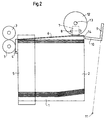
- the feeder shown in FIGS. 1 to 6 contains a sheet support plate 1 which can be moved in height and a sheet stack 2 resting on the sheet support plate 1.
- a printing machine connects to a front of the feeder, of which only transport rollers 3 are shown, which are rotatably mounted parallel to the front edge of the sheet stack 2.
- transport rollers 3 which are rotatably mounted parallel to the front edge of the sheet stack 2.
- Movable front stacking stops 4 and stationary side stacking stops 5 are also arranged at the front of the feeder.
- the sheet support plate 1 is flat in its front and middle area. In the area of the two rear corners of the sheet support plate 1, that is, facing away from the printing press, the top of the sheet support plate 1 is designed such that it extends from the flat area towards the corners increases.
- the sheet support plate 1 thus has an at least partially concave upper side.
- the sheet stack 2 resting on the sheet support plate 1 assumes essentially the same shape, so that the two rear, upper corners of the sheet stack 2 lie higher than its remaining surface.
- a friction wheel 7 is arranged in the area of the two rear corners, which has an axis 8 which extends parallel to the side edges of the sheet 6.
- the friction wheels 7 are resiliently biased towards the top of the uppermost sheet 6 by means not shown, whereby they can deflect resiliently upwards.
- the position of the friction wheels 7 and thus the top edge of the stack can be detected by sensors, not shown, in order to keep the top of the sheet stack 2 at the same height by moving the sheet support plate 1 during operation.
- the friction wheels 7 then press on the rear corners of the uppermost sheet 6 with a defined force.
- the axes 8 of the friction wheels 7 are connected to drive devices (not shown) for rotating the friction wheels 7.
- a feeler foot 9 which has an elongated touch finger 10 which runs approximately parallel to the top of the sheet stack 2.
- the feeler foot 9 is movable in the direction of the sheet stack 2 and away from it by being pivotable about a pivot point 11 in the sheet plane of FIG. 2.
- the feeler 9 can be linearly movable or pivotable about a pivot point that lies in the plane of the top of the sheet stack 2.
- Drive means are provided for moving the feeler foot 9.
- a friction wheel 12 is arranged, which has an axis 13 which is parallel to the The rear edge of the sheet stack 2 extends.
- the friction wheel 12 is located exactly above the touch finger 10 of the touch foot 9 when the touch foot 9 has been pivoted in the direction of the sheet stack 2.
- the friction wheel 12 and its axis 13 can be moved from above in the direction of the sheet stack 2 or the touch finger 10 and away therefrom.
- Drive means are provided for this movement and for a rotation of the friction wheel 12.
- the friction wheels 7 are first rotated in opposite directions, as indicated by arrows in FIG. 1, so that the top sheet 6 is pulled apart and stretched between the friction wheels 7. In this way, an intermediate space 14 is formed between the two uppermost sheets of the sheet stack 2.
- 9 wiper springs or wiping brushes can be provided on the side next to the feeler foot, which press against the rear edge of the sheet stack 2 (not shown in the drawings) ).
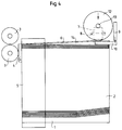
- the feeler foot 9 swivels without contact from the rear into the resulting space 14.
- the feeler finger 10 extends over the vertical center line of the friction wheel 12 has penetrated into the intermediate space 14.
- the feeler 9 lowers below the uppermost sheet 6 onto the sheet stack 2 in order to hold the remaining sheets on the sheet stack 2.
- This lowering process can be carried out separately, as indicated by an arrow in FIG. 4, or, if the pivot point 11 is suitably arranged, can result from the pivoting movement of the feeler foot 9.
- the friction wheel 12 lowers, as indicated by a further arrow in FIG. 4, the uppermost sheet 6 being clamped between the friction wheel 12 and the touch finger 10. 5
- the movable stack stops 4 are then pivoted away from the sheet stack 2 and the friction wheel 12 is rotated in the direction of the arrow shown.
- the top of the finger 10 is z. B. a polished metal surface, which has a low coefficient of friction compared to the sheet 6 compared to the friction wheel 12.
- the friction rollers 7 can be lifted off the sheet 6 in the meantime by means not shown. But it is also conceivable that the bias of the friction rollers 7 is so low that the sheet transport is not hindered.
- the length of the touch finger 10 or the distance of the transport rollers 3 from the sheet stack 2 are chosen so that the top sheet 6 is gripped in time by the transport rollers 3 when it exits between the friction wheel 12 and the touch finger 10.
- the friction wheel 12 As soon as the uppermost sheet 6 has emerged between the friction wheel 12 and the touch finger 10 of the touch foot, the friction wheel 12, the touch foot 9 and possibly the friction wheels 7 are brought back into the positions shown in FIG. 2. Thereafter, the next singling cycle can be started immediately while the sheet 6 is still being pulled off the sheet stack 2, whereby it z. B. is in the position shown in dashed lines in Fig. 6. During the removal from the sheet stack 2, the sheet 6 is guided through the side stack stops 5.
- Tensioning the uppermost sheet and reaching into the resulting space can not only be carried out on the trailing edge of the sheet, but alternatively or additionally on the side edges. Furthermore, it can be carried out on the leading edge of the sheet, as will be described below with reference to FIG. 7.
- a sheet stack 15 is concavely curved in its front region by using a correspondingly curved sheet support plate 16.
- Two friction wheels 17 correspond in structure and function to the friction wheels 7 of the previous embodiment, but are arranged above the front corners of the sheet stack 15.
- One or more grippers 18 are attached to a rotatable gripper bar 19, which is arranged in front of the sheet stack 15.
- the grippers 18 pivot to the front edge 21 of the uppermost sheet 20, grasp the sheet 20 at the front edge 21 and pull it off the sheet stack 15, to feed it to a printing press.
- the remaining sheets are retained by a front stacking stop 22, over which the top sheet 20 is raised when the space 23 between the top two sheets is formed.
- 22 stripping springs or stripping brushes can be provided on the side next to the front stacking stop.
- the embodiment of FIG. 7 does not allow quite as high working speeds as the previous embodiment, since the sheets cannot be pulled overlapping from the sheet stack.
- very few moving parts are required, the masses of which can moreover be kept small, so that the working speeds are more conventional Single sheet feeders can be easily reached or surpassed without excessive acceleration and the associated vibrations.
- the sheet separation is carried out by tensioning the top sheet much more reliably, with significantly less effort and with much less noise than with a conventional single sheet feeder working with air.
Landscapes
- Engineering & Computer Science (AREA)
- Mechanical Engineering (AREA)
- Sheets, Magazines, And Separation Thereof (AREA)
Applications Claiming Priority (2)
| Application Number | Priority Date | Filing Date | Title |
|---|---|---|---|
| DE19543382 | 1995-11-21 | ||
| DE19543382A DE19543382C2 (de) | 1995-11-21 | 1995-11-21 | Verfahren zum Vereinzeln von Bogen und Anleger für eine Bogendruckmaschine zur Durchführung des Verfahrens |
Publications (3)
| Publication Number | Publication Date |
|---|---|
| EP0775656A2 true EP0775656A2 (fr) | 1997-05-28 |
| EP0775656A3 EP0775656A3 (fr) | 1998-09-09 |
| EP0775656B1 EP0775656B1 (fr) | 2002-08-07 |
Family
ID=7778025
Family Applications (1)
| Application Number | Title | Priority Date | Filing Date |
|---|---|---|---|
| EP96118618A Expired - Lifetime EP0775656B1 (fr) | 1995-11-21 | 1996-11-20 | Margeur et procédé de séparation des feuilles |
Country Status (5)
| Country | Link |
|---|---|
| US (1) | US5915682A (fr) |
| EP (1) | EP0775656B1 (fr) |
| JP (1) | JPH09169442A (fr) |
| AU (1) | AU7186196A (fr) |
| DE (2) | DE19543382C2 (fr) |
Families Citing this family (10)
| Publication number | Priority date | Publication date | Assignee | Title |
|---|---|---|---|---|
| DE10147410B4 (de) * | 2001-09-26 | 2005-08-18 | Helmut Steinhilber | Verfahren und Vorrichtung zum Vereinzeln von Blättern von einem Stapel |
| DE102004017348B3 (de) * | 2004-04-06 | 2005-04-21 | Helmut Steinhilber | Vorrichtung zum Vereinzeln von in einem Stapel vorgehaltenen Blättern |
| JP2007204164A (ja) * | 2006-01-30 | 2007-08-16 | Fujifilm Corp | 平版刷版の自動供給装置 |
| JP2007204162A (ja) * | 2006-01-30 | 2007-08-16 | Fujifilm Corp | 平版刷版の自動供給装置 |
| WO2007086580A1 (fr) * | 2006-01-30 | 2007-08-02 | Fujifilm Corporation | Dispositif d'amenee automatique de plaques d'impression lithographique |
| JP2007246205A (ja) * | 2006-03-15 | 2007-09-27 | Fujifilm Corp | 平版刷版の自動供給装置 |
| US9682415B2 (en) * | 2014-03-26 | 2017-06-20 | Novelis Inc. | De-stacking process for the separation of lubricated aluminum sheets |
| US10421629B2 (en) | 2017-03-02 | 2019-09-24 | Kabushiki Kaisha Toshiba | Paper feed apparatus and image forming apparatus |
| CN111747157A (zh) * | 2020-07-27 | 2020-10-09 | 机械科学研究总院海西(福建)分院有限公司 | 一种胶带式铺席工装夹持装置 |
| DE102022122393A1 (de) | 2021-09-07 | 2023-03-09 | Mabeg Systems Gmbh | Variable Bogenzufuhr |
Family Cites Families (8)
| Publication number | Priority date | Publication date | Assignee | Title |
|---|---|---|---|---|
| US2827288A (en) * | 1954-11-23 | 1958-03-18 | Old Town Corp | Sheet feeding device |
| US3627307A (en) * | 1970-02-26 | 1971-12-14 | Optische Ind De Oude Delft Nv | Film-changing device |
| US4165870A (en) * | 1978-03-20 | 1979-08-28 | International Business Machines Corporation | Wave generator to shingle sheets |
| JPS58139932A (ja) * | 1982-02-10 | 1983-08-19 | Sharp Corp | エア−吸引式シ−ト原稿吸着装置 |
| DE3211371C2 (de) * | 1982-03-27 | 1984-02-09 | Fraunhofer-Gesellschaft zur Förderung der angewandten Forschung e.V., 8000 München | Vorrichtung zum Vereinzeln des jeweils obersten Blattes eines Stapels von blattförmigem Gut |
| SU1315090A1 (ru) * | 1985-07-29 | 1987-06-07 | Ростовский научно-исследовательский институт технологии машиностроения | Способ отделени верхнего листа от стопы |
| JPS63247237A (ja) * | 1987-03-31 | 1988-10-13 | Kao Corp | 薄葉物の分離装置 |
| SU1680606A1 (ru) * | 1989-02-03 | 1991-09-30 | Московский Полиграфический Институт | Способ поштучной подачи от стопы гибкого листового материала |
-
1995
- 1995-11-21 DE DE19543382A patent/DE19543382C2/de not_active Expired - Fee Related
-
1996
- 1996-11-20 DE DE59609537T patent/DE59609537D1/de not_active Expired - Lifetime
- 1996-11-20 AU AU71861/96A patent/AU7186196A/en not_active Abandoned
- 1996-11-20 EP EP96118618A patent/EP0775656B1/fr not_active Expired - Lifetime
- 1996-11-21 JP JP8310898A patent/JPH09169442A/ja active Pending
- 1996-11-21 US US08/759,826 patent/US5915682A/en not_active Expired - Lifetime
Non-Patent Citations (1)
| Title |
|---|
| None |
Also Published As
| Publication number | Publication date |
|---|---|
| EP0775656B1 (fr) | 2002-08-07 |
| DE19543382C2 (de) | 1999-05-27 |
| DE59609537D1 (de) | 2002-09-12 |
| US5915682A (en) | 1999-06-29 |
| AU7186196A (en) | 1997-05-29 |
| JPH09169442A (ja) | 1997-06-30 |
| DE19543382A1 (de) | 1997-05-28 |
| EP0775656A3 (fr) | 1998-09-09 |
Similar Documents
| Publication | Publication Date | Title |
|---|---|---|
| DE3418344C2 (fr) | ||
| DE3531889C2 (de) | Vereinzelungsvorrichtung für das oberste Blatt eines Blattstapels mit einem die Vorderseite des Blattstapels mit Blasluft beaufschlagenden Luftmesser | |
| DE2638767C2 (de) | Bogenvereinzelungsvorrichtung | |
| DE2649959A1 (de) | Vorrichtung zur uebergabe eines teilstapels bedruckter boegen von einem gesamtstapel in eine ruettelstation | |
| DE19543382C2 (de) | Verfahren zum Vereinzeln von Bogen und Anleger für eine Bogendruckmaschine zur Durchführung des Verfahrens | |
| EP0417503A1 (fr) | Procédé et dispositif pour le traitement ultérieur de produits imprimés empilés, de préférence pliés | |
| DE2244249C2 (de) | Blattzuführvorrichtung | |
| DE3785316T2 (de) | Blattzufuehrvorrichtung. | |
| EP0773179B1 (fr) | Dispositif pour faire des piles auxiliaires pendant l'échange en continue de piles dans un empileur d'une machine à imprimer | |
| CH652344A5 (de) | Vorgreifer einer bogenanlegevorrichtung. | |
| DE2628809A1 (de) | Vorrichtung und verfahren zur einzelzufuehrung gestapelter gegenstaende | |
| DE202006013884U1 (de) | Vorichtung zur Herstellung und Kontrolle von Mustern tragenden Bögen mit Hilfe eines Vakuumtransportförderers | |
| EP1770036B1 (fr) | Dispositif de guidage de feuilles pour un margeur de feuilles | |
| DE19649341A1 (de) | Verfahren und Non-Stop-Auslegervorrichtung für eine bogenverarbeitende Druckmaschine | |
| DE19614491A1 (de) | Bogenbremse im Ausleger einer Druckmaschine | |
| DE10258038B4 (de) | Verfahren und Vorrichtung zur Vereinzelung der Blätter eines Aufzeichnungsträgers von einem Stapel | |
| DE10159933B4 (de) | Papierentladevorrichtung für eine Zylinder-Siebdruckmaschine | |
| DE4214232C1 (de) | Bogenanleger mit im bereich der stapelhinterkante angeordneten trennsaugern | |
| DE3531145C2 (fr) | ||
| DE3210942A1 (de) | Vorrichtung zum seitlichen ausrichten des obersten bogens eines bogenstapels | |
| DE2753048C2 (de) | Verfahren und Vorrichtung zur Herstellung einer gebündelten Stange aus Druckbogen | |
| DE102020116074B4 (de) | Vorrichtung und Verfahren zum Ablegen und Positionieren eines Stapelbildungshilfsmittels | |
| DE19645239B4 (de) | Bogenanlage, insbesondere für Druckmaschinen | |
| DE4447204C2 (de) | Saugkopf | |
| DE3912458A1 (de) | Einrichtung zum kontinuierlichen vorausrichten der bogenvorderkante in bogenanlegern |
Legal Events
| Date | Code | Title | Description |
|---|---|---|---|
| PUAI | Public reference made under article 153(3) epc to a published international application that has entered the european phase |
Free format text: ORIGINAL CODE: 0009012 |
|
| 17P | Request for examination filed |
Effective date: 19961121 |
|
| AK | Designated contracting states |
Kind code of ref document: A2 Designated state(s): CH DE ES FR GB LI NL |
|
| PUAL | Search report despatched |
Free format text: ORIGINAL CODE: 0009013 |
|
| AK | Designated contracting states |
Kind code of ref document: A3 Designated state(s): CH DE ES FR GB LI NL |
|
| 17Q | First examination report despatched |
Effective date: 20000728 |
|
| GRAG | Despatch of communication of intention to grant |
Free format text: ORIGINAL CODE: EPIDOS AGRA |
|
| GRAG | Despatch of communication of intention to grant |
Free format text: ORIGINAL CODE: EPIDOS AGRA |
|
| GRAH | Despatch of communication of intention to grant a patent |
Free format text: ORIGINAL CODE: EPIDOS IGRA |
|
| GRAH | Despatch of communication of intention to grant a patent |
Free format text: ORIGINAL CODE: EPIDOS IGRA |
|
| GRAA | (expected) grant |
Free format text: ORIGINAL CODE: 0009210 |
|
| AK | Designated contracting states |
Kind code of ref document: B1 Designated state(s): CH DE ES FR GB LI NL |
|
| PG25 | Lapsed in a contracting state [announced via postgrant information from national office to epo] |
Ref country code: NL Free format text: LAPSE BECAUSE OF FAILURE TO SUBMIT A TRANSLATION OF THE DESCRIPTION OR TO PAY THE FEE WITHIN THE PRESCRIBED TIME-LIMIT Effective date: 20020807 |
|
| REG | Reference to a national code |
Ref country code: GB Ref legal event code: FG4D Free format text: NOT ENGLISH |
|
| REG | Reference to a national code |
Ref country code: CH Ref legal event code: EP |
|
| REF | Corresponds to: |
Ref document number: 59609537 Country of ref document: DE Date of ref document: 20020912 |
|
| GBT | Gb: translation of ep patent filed (gb section 77(6)(a)/1977) |
Effective date: 20020902 |
|
| NLV1 | Nl: lapsed or annulled due to failure to fulfill the requirements of art. 29p and 29m of the patents act | ||
| PG25 | Lapsed in a contracting state [announced via postgrant information from national office to epo] |
Ref country code: FR Free format text: LAPSE BECAUSE OF FAILURE TO SUBMIT A TRANSLATION OF THE DESCRIPTION OR TO PAY THE FEE WITHIN THE PRESCRIBED TIME-LIMIT Effective date: 20030221 |
|
| ET | Fr: translation filed | ||
| PG25 | Lapsed in a contracting state [announced via postgrant information from national office to epo] |
Ref country code: ES Free format text: LAPSE BECAUSE OF FAILURE TO SUBMIT A TRANSLATION OF THE DESCRIPTION OR TO PAY THE FEE WITHIN THE PRESCRIBED TIME-LIMIT Effective date: 20030228 |
|
| PLBE | No opposition filed within time limit |
Free format text: ORIGINAL CODE: 0009261 |
|
| STAA | Information on the status of an ep patent application or granted ep patent |
Free format text: STATUS: NO OPPOSITION FILED WITHIN TIME LIMIT |
|
| 26N | No opposition filed |
Effective date: 20030508 |
|
| PGFP | Annual fee paid to national office [announced via postgrant information from national office to epo] |
Ref country code: GB Payment date: 20141121 Year of fee payment: 19 Ref country code: CH Payment date: 20141125 Year of fee payment: 19 Ref country code: DE Payment date: 20141126 Year of fee payment: 19 |
|
| PGFP | Annual fee paid to national office [announced via postgrant information from national office to epo] |
Ref country code: FR Payment date: 20141120 Year of fee payment: 19 |
|
| REG | Reference to a national code |
Ref country code: DE Ref legal event code: R119 Ref document number: 59609537 Country of ref document: DE |
|
| REG | Reference to a national code |
Ref country code: CH Ref legal event code: PL |
|
| GBPC | Gb: european patent ceased through non-payment of renewal fee |
Effective date: 20151120 |
|
| PG25 | Lapsed in a contracting state [announced via postgrant information from national office to epo] |
Ref country code: LI Free format text: LAPSE BECAUSE OF NON-PAYMENT OF DUE FEES Effective date: 20151130 Ref country code: CH Free format text: LAPSE BECAUSE OF NON-PAYMENT OF DUE FEES Effective date: 20151130 |
|
| REG | Reference to a national code |
Ref country code: FR Ref legal event code: ST Effective date: 20160729 |
|
| PG25 | Lapsed in a contracting state [announced via postgrant information from national office to epo] |
Ref country code: GB Free format text: LAPSE BECAUSE OF NON-PAYMENT OF DUE FEES Effective date: 20151120 Ref country code: DE Free format text: LAPSE BECAUSE OF NON-PAYMENT OF DUE FEES Effective date: 20160601 |
|
| PG25 | Lapsed in a contracting state [announced via postgrant information from national office to epo] |
Ref country code: FR Free format text: LAPSE BECAUSE OF FAILURE TO SUBMIT A TRANSLATION OF THE DESCRIPTION OR TO PAY THE FEE WITHIN THE PRESCRIBED TIME-LIMIT Effective date: 20151130 |