EP0776805A2 - Antriebseinheit - Google Patents
Antriebseinheit Download PDFInfo
- Publication number
- EP0776805A2 EP0776805A2 EP96117213A EP96117213A EP0776805A2 EP 0776805 A2 EP0776805 A2 EP 0776805A2 EP 96117213 A EP96117213 A EP 96117213A EP 96117213 A EP96117213 A EP 96117213A EP 0776805 A2 EP0776805 A2 EP 0776805A2
- Authority
- EP
- European Patent Office
- Prior art keywords
- retarder
- shaft
- drive unit
- wall
- bearings
- Prior art date
- Legal status (The legal status is an assumption and is not a legal conclusion. Google has not performed a legal analysis and makes no representation as to the accuracy of the status listed.)
- Granted
Links
- 238000007789 sealing Methods 0.000 claims abstract 4
- 239000012208 gear oil Substances 0.000 claims description 3
- 239000000314 lubricant Substances 0.000 claims description 2
- 230000005540 biological transmission Effects 0.000 abstract description 11
- 230000004323 axial length Effects 0.000 abstract 1
- 239000002826 coolant Substances 0.000 description 3
- 239000003921 oil Substances 0.000 description 3
- 238000001816 cooling Methods 0.000 description 2
- 239000000498 cooling water Substances 0.000 description 2
- XLYOFNOQVPJJNP-UHFFFAOYSA-N water Substances O XLYOFNOQVPJJNP-UHFFFAOYSA-N 0.000 description 2
- 239000012530 fluid Substances 0.000 description 1
- 238000004519 manufacturing process Methods 0.000 description 1
Images

Classifications
-
- F—MECHANICAL ENGINEERING; LIGHTING; HEATING; WEAPONS; BLASTING
- F16—ENGINEERING ELEMENTS AND UNITS; GENERAL MEASURES FOR PRODUCING AND MAINTAINING EFFECTIVE FUNCTIONING OF MACHINES OR INSTALLATIONS; THERMAL INSULATION IN GENERAL
- F16H—GEARING
- F16H57/00—General details of gearing
- F16H57/04—Features relating to lubrication or cooling or heating
- F16H57/0467—Elements of gearings to be lubricated, cooled or heated
- F16H57/0469—Bearings or seals
-
- B—PERFORMING OPERATIONS; TRANSPORTING
- B60—VEHICLES IN GENERAL
- B60T—VEHICLE BRAKE CONTROL SYSTEMS OR PARTS THEREOF; BRAKE CONTROL SYSTEMS OR PARTS THEREOF, IN GENERAL; ARRANGEMENT OF BRAKING ELEMENTS ON VEHICLES IN GENERAL; PORTABLE DEVICES FOR PREVENTING UNWANTED MOVEMENT OF VEHICLES; VEHICLE MODIFICATIONS TO FACILITATE COOLING OF BRAKES
- B60T1/00—Arrangements of braking elements, i.e. of those parts where braking effect occurs specially for vehicles
- B60T1/02—Arrangements of braking elements, i.e. of those parts where braking effect occurs specially for vehicles acting by retarding wheels
- B60T1/08—Arrangements of braking elements, i.e. of those parts where braking effect occurs specially for vehicles acting by retarding wheels using fluid or powdered medium
- B60T1/087—Arrangements of braking elements, i.e. of those parts where braking effect occurs specially for vehicles acting by retarding wheels using fluid or powdered medium in hydrodynamic, i.e. non-positive displacement, retarders
-
- F—MECHANICAL ENGINEERING; LIGHTING; HEATING; WEAPONS; BLASTING
- F16—ENGINEERING ELEMENTS AND UNITS; GENERAL MEASURES FOR PRODUCING AND MAINTAINING EFFECTIVE FUNCTIONING OF MACHINES OR INSTALLATIONS; THERMAL INSULATION IN GENERAL
- F16D—COUPLINGS FOR TRANSMITTING ROTATION; CLUTCHES; BRAKES
- F16D57/00—Liquid-resistance brakes; Brakes using the internal friction of fluids or fluid-like media, e.g. powders
- F16D57/04—Liquid-resistance brakes; Brakes using the internal friction of fluids or fluid-like media, e.g. powders with blades causing a directed flow, e.g. Föttinger type
-
- Y—GENERAL TAGGING OF NEW TECHNOLOGICAL DEVELOPMENTS; GENERAL TAGGING OF CROSS-SECTIONAL TECHNOLOGIES SPANNING OVER SEVERAL SECTIONS OF THE IPC; TECHNICAL SUBJECTS COVERED BY FORMER USPC CROSS-REFERENCE ART COLLECTIONS [XRACs] AND DIGESTS
- Y10—TECHNICAL SUBJECTS COVERED BY FORMER USPC
- Y10T—TECHNICAL SUBJECTS COVERED BY FORMER US CLASSIFICATION
- Y10T74/00—Machine element or mechanism
- Y10T74/19—Gearing
- Y10T74/19633—Yieldability in gear trains
-
- Y—GENERAL TAGGING OF NEW TECHNOLOGICAL DEVELOPMENTS; GENERAL TAGGING OF CROSS-SECTIONAL TECHNOLOGIES SPANNING OVER SEVERAL SECTIONS OF THE IPC; TECHNICAL SUBJECTS COVERED BY FORMER USPC CROSS-REFERENCE ART COLLECTIONS [XRACs] AND DIGESTS
- Y10—TECHNICAL SUBJECTS COVERED BY FORMER USPC
- Y10T—TECHNICAL SUBJECTS COVERED BY FORMER US CLASSIFICATION
- Y10T74/00—Machine element or mechanism
- Y10T74/21—Elements
- Y10T74/2186—Gear casings
Definitions
- the invention relates to a drive unit for a motor vehicle with an engine, a hydrodynamic retarder and a transmission.
- Retarders play an increasingly important role in vehicle drive systems. They are integrated in the drive train. When used in a motor vehicle - but also in systems with strongly changing operation - the retarder is switched on or off by filling and emptying the bladed working circuit with a working medium.
- the working medium is e.g. Consider oil or water. If the retarder does the braking work, the working medium is heated. The heat must be dissipated through a cooler.
- Drive units of motor vehicles generally have other units that require cooling.
- the engine, the mechanical brakes, the clutch or the gearbox should be considered.
- These other units can also have a cooling circuit.
- the retarder In a drive system for vehicles, it is known to operate the retarder with water, which simultaneously serves as cooling water. In the non-braking mode, the retarder can optionally be used as a pump and the working medium of the retarder can simultaneously serve as a cooling medium for other units in the drive unit.
- D 195 09 417 A1 shows and describes a drive train for a motor vehicle with an engine, a transmission and a retarder.
- the retarder is integrated in the gearbox end housing.
- the object of the invention is to further improve such a drive train in such a way that the manufacture and assembly of the retarder and transmission become even simpler, more efficient and therefore less expensive.
- the arrangement according to the invention is such that the retarder can be plugged onto the retarder shaft as an independent structural unit.
- the retarder shaft is now mounted in a wall part that is part of the gearbox.
- the retarder shaft is mounted in this wall part and protrudes beyond the wall part, so that it can accommodate the completely pre-assembled retarder by plugging it on.
- a seal is integrated into the above-mentioned wall, which has a double function: on the one hand, it seals against the gear oil, on the other hand against the working medium of the retarder.
- the retarder can be operated with a working medium other than oil.
- a drive train is shown schematically in FIG. 1, comprising a motor 1, a transmission 2, a hydrodynamic retarder 3 with a cooling medium as working medium, a heat exchanger 4, a fan 5 assigned to it, a circulating pump 6, cooling water lines 7 and an expansion tank 8.
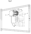
- FIG. 2 shows a partial view of the arrangement according to the invention with parts of the transmission 2 shown in broken lines and with the retarder 3.
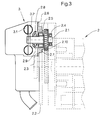
- the retarder has a rotor blade wheel 3.1 and a stator blade wheel 3.2. It is mounted on a shaft 2.1. Wave 2.1 is in turn in one Outer wall of the gearbox 2 is mounted. This can be seen more precisely from FIG. 3.
- the gear 2 has a housing 2.2.
- a cover 2.3 is inserted into the housing wall.
- Cover 2.3 is screwed to the rest of the housing wall of gearbox 2.2 and is sealed against it.
- the retarder shaft 2.1 is supported by two bearings 2.4 and 2.5.
- Bearing 2.4 is located within the space enclosed by gearbox 2.2, while bearing 2.5 is arranged in cover 2.3.
- Retarder 3 is preassembled as an independent unit and plugged onto the retarder shaft 2.1 from the outside. It is conceivable to attach retarder 3 partially assembled.
- Cover 2.3 has an outer boundary surface 2.6, on which the retarder assembly 3 is placed, and an inner boundary surface 2.7, which is inserted into a corresponding recess in the retarder housing 2.2.
- Lid 2.3 also carries a seal 2.8.
- This seal 2.8 has a double function: it seals the annular gap between cover 2.3 and retarder shaft 2.1 on the one hand against the gear oil and on the other hand against the working medium of the retarder 3, in this case a cooling medium.
- the seal can be designed as a single element or as a double element.
- a leakage hole 2.9 can also be seen in cover 2.3. This serves to discharge leakage fluid to the outside.
- the retarder shaft 2.1 also carries a pinion 2.10. This is part of a high gear, with which the retarder shaft 2.1 is brought to higher speeds.
- the rotor blade wheel 3.1 and the stator blade wheel 3.2 can be interchanged in the axial direction, so that the rotor blade wheel 3.1 is closer to the cover 2.3 than the stator blade wheel compared to the illustration in FIG. 3.
Landscapes
- Engineering & Computer Science (AREA)
- General Engineering & Computer Science (AREA)
- Mechanical Engineering (AREA)
- Physics & Mathematics (AREA)
- Fluid Mechanics (AREA)
- Transportation (AREA)
- Braking Arrangements (AREA)
- Brushes (AREA)
- Valve Device For Special Equipments (AREA)
- Vehicle Body Suspensions (AREA)
- Arrangement Of Transmissions (AREA)
- Connection Of Motors, Electrical Generators, Mechanical Devices, And The Like (AREA)
- General Details Of Gearings (AREA)
- Control Of Driving Devices And Active Controlling Of Vehicle (AREA)
Abstract
- mit einem Motor (1);
- mit einem Getriebe (2), das ein Getriebegehäuse (2.2) aufweist;
- mit einem Retarder (3) , der einen Rotor (3.1) und einen Stator (3.2) aufweist;
- es ist eine Retarderwelle (2.1) vorgesehen, die von zwei in Achsrichtung der Retarderwelle versetzt angeordneten Lagern (2.4,2.5) getragen ist;
- wenigstens eines der Lager ("Außenlager") ist von einer Wandung ("Außenwandung") (2.3) des Getriebegehäuses getragen;
- die Retarderwelle ragt frei über die Außenwandung des Getriebegehäuses hinaus;
- auf der Retarderwelle außerhalb des Außenlagers befindet sich an der Außenwandung ein Dichtelement (2.9);
- das Dichtelement dichtet den Spaltraum zwischen der Ritzelwelle (2.1) und der Außenwandung (2.3) einerseits gegen das Getriebeöl und andererseits gegen das Arbeitsmedium des Retarders ab.
Description
- Die Erfindung betrifft eine Antriebseinheit für ein Kraftfahrzeug mit einem Motor, einem hydrodynamischen Retarder und einem Getriebe.
- Retarder spielen bei Antriebsanlagen von Fahrzeugen eine immer wichtigere Rolle. Sie sind in den Antriebsstrang integriert. Der Retarder wird beim Einsatz im Kraftfahrzeug - aber auch bei Anlagen mit stark wechselndem Betrieb - durch Füllen und Entleeren des beschaufelten Arbeitskreislaufes mit einem Arbeitsmedium ein- oder ausgeschaltet. Als Arbeitsmedium kommen z.B. Öl oder Wasser in Betracht. Leistet der Retarder Bremsarbeit, so wird das Arbeitsmedium erwärmt. Die Wärme muß durch einen Kühler abgeführt werden.
- Antriebseinheiten von Kraftfahrzeugen haben in der Regel weitere Aggregate, die eine Kühlung benötigen. Hierbei ist beispielsweise an den Motor, die mechanischen Bremsen, an die Kupplung oder an das Getriebe zu denken. Diese anderen Aggregate können ebenfalls einen Kühlkreislauf aufweisen. Es ist bekannt, bei einer Antriebsanlage für Fahrzeuge den Retarder mit Wasser zu betreiben, das gleichzeitig als Kühlwasser dient. Dabei kann der Retarder im Nicht-Bremsbetrieb wahlweise als Pumpe verwendet werden und das Arbeitsmedium des Retarders, gleichzeitig als Kühlmedium für andere Aggregate der Antriebseinheit dienen.
- D 195 09 417 A1 zeigt und beschreibt einen Antriebsstrang für ein Kraftfahrzeug mit einem Motor, einem Getriebe und einem Retarder. Dabei ist der Retarder in das Getriebeendgehäuse integriert.
- Der Erfindung liegt die Aufgabe zugrunde, einen solchen Antriebsstrang dahingehend weiterzuverbessern, daß Fertigung und Montage von Retarder und Getriebe noch einfacher, rationeller und damit kostengünstiger werden.
- Diese Aufgabe wird durch die Merkmale von Anspruch 1 gelöst.
- Anders als bei der genannten Druckschrift wird gemäß der Erfindung die Anordnung so getroffen, daß der Retarder als selbständige Baueinheit auf die Retarderwelle aufsteckbar ist. Die Retarderwelle wird nunmehr in einem Wandteil gelagert, das Bestandteil des Getriebegehäuses ist. Die Retarderwelle ist in diesem Wandteil gelagert und ragt über das Wandteil hinaus, so daß es den komplett vormontierten Retarder durch Aufstecken aufnehmen kann. In das genannte Wandte ist außerdem eine Dichtung integriert, die eine Doppelfunktion hat: Zum einen dichtet sie gegen das Getriebeöl ab, zum anderen gegen das Arbeitsmedium des Retarders. Der Retarder kann mit einem anderen Arbeitsmedium betrieben werden als Öl. In diesem Falle muß dafür gesorgt werden, daß die beiden Medien, nämlich das Arbeitsmedium des Retarders einerseits und das Schmiermittel des Getriebes andererseits nicht in leitender Verbindung miteinander stehen. Dies wird durch die genannte Dichtung erreicht. Dies schließt natürlich nicht aus, daß beide Medien miteinander identisch sind, so daß auch der Retarder mit Öl als Arbeitsmedium betrieben wird.
- Die Erfindung ist anhand der Zeichnung näher erläutert.
- In Figur 1 ist schematisch ein Antriebsstrang dargestellt, umfassend einen Motor 1, ein Getriebe 2, einen hydrodynamischen Retarder 3 mit einem Kühlmedium als Arbeitsmedium, einen Wärmetauscher 4, einen diesem zugeordneten Lüfter 5, eine Umwälzpumpe 6, Kühlwasserleitungen 7 sowie einen Ausgleichsbehälter 8.
- Figur 2 zeigt in einer Teilansicht die erfindungsgemäße Anordnung mit gestrichelt dargestellten Teilen des Getriebes 2 und mit dem Retarder 3. Der Retarder weist ein Rotorschaufelrad 3.1 sowie ein Statorschaufelrad 3.2 auf. Er ist auf einer Welle 2.1 gelagert. Welle 2.1 ist ihrerseits unter anderem in einer Außen-Wandung des Getriebes 2 gelagert. Dies ergibt sich noch genauer aus Figur 3.
- Das Getriebe 2 weist ein Gehäuse 2.2 auf. In die Gehäusewandung ist ein Deckel 2.3 eingesetzt. Deckel 2.3 ist mit der übrigen Gehäusewandung des Getriebegehäuses 2.2 verschraubt und hierbei gegen dieses abgedichtet. Die Retarderwelle 2.1 ist mittels zweier Lager 2.4 und 2.5 gelagert. Dabei befindet sich Lager 2.4 innerhalb des vom Getriebegehäuse 2.2 umschlossenen Raumes, während Lager 2.5 in Deckel 2.3 angeordnet ist.
- Retarder 3 ist als selbständige Baueinheit vormontiert und auf die Retarderwelle 2.1 von außen her aufgesteckt. Es ist denkbar, Retarder 3 teilmontiert aufzustecken.
- Deckel 2.3 weist eine äußere Begrenzungsfläche 2.6 auf, auf welche die Retarder-Baueinheit 3 aufgesetzt ist, ferner eine innere Begrenzungsfläche 2.7, die in eine entsprechende Aussparung des Retardergehäuses 2.2 eingefügt ist.
- Deckel 2.3 trägt außerdem eine Dichtung 2.8. Diese Dichtung 2.8 hat eine Doppelfunktion: Sie dichtet den Ringspalt zwischen Deckel 2.3 und Retarderwelle 2.1 einerseits gegen das Getriebeöl ab und andererseits gegen das Arbeitsmedium des Retarders 3, in diesem Falle ein Kühlmedium. Die Dichtung kann als einziges Element oder als Doppelelement ausgebildet sein.
- Man erkennt ferner eine Leckagebohrung 2.9 in Deckel 2.3. Diese dient der Abfuhr von Leckflüssigkeit nach außen.
- Die Retarderwelle 2.1 trägt ferner ein Ritzel 2.10. Dies ist Bestandteil eines Hochganges, mit dem die Retarderwelle 2.1 auf höhere Drehzahlen gebracht wird.
- Beim Retarder 3 können Rotorschaufelrad 3.1 und Statorschaufelrad 3.2 in axialer Richtung vertauscht werden, so daß gegenüber der Darstellung gemäß Figur 3 das Rotorschaufelrad 3.1 dem Deckel 2.3 näher ist als das Statorschaufelrad.
Claims (5)
- Antriebseinheit für ein Kraftfahrzeug;1.1 mit einem Motor (1);1.2 mit einem Getriebe (2), das ein Getriebegehäuse (2.2) aufweist;1.3 mit einem Retarder (3), der einen Rotor (3.1) und einen Stator (3.2) aufweist;1.4 es ist eine Retarderwelle (2.1) vorgesehen, die im Getriebe gelagert und von wenigstens zwei Lagern (2.4, 2.5) getragen ist;1.5 die Retarderwelle (2.1) ragt frei über die Außenwandung (2.3) des Getriebegehäuses (2.2) hinaus;1.6 auf der Retarderwelle (2.1) befindet sich an der Außenwandung (2.3) des Getriebegehäuses (2.2) wenigstens ein Dichtelement (2.9);1.7 das Dichtelement dichtet den Spaltraum zwischen der Ritzelwelle (2.1) und der Außenwandung (2.3) einerseits gegen das Getriebeöl und andererseits gegen das Arbeitsmedium des Retarders ab;1.8 das Schmiermittel des Getriebes (2) ist vom Arbeitsmedium des Retarders getrennt.
- Antriebseinheit nach Anspruch 1, dadurch gekennzeichnet, daß derjenige Teil der Außenwandung (2,3), der den Retarder bzw. die Retarderwelle trägt, als Deckel ausgebildet und mit dem übrigen Getriebegehäuse (2.2) verbunden ist.
- Antriebseinheit nach Anspruch 1 oder 2, dadurch gekennzeichnet, daß die Retarderwelle (2.1) zugleich ein Ritzel (2.10) eines Hochganges trägt.
- Antriebseinheit nach Anspruch 3, dadurch gekennzeichnet, daß das Ritzel (2.10) in axialer Richtung auf der einen oder der anderen der beiden Lager (2.4, 2.5) oder zwischen diesen beiden Lagern angeordnet ist.
- Antriebseinheit nach einem der Ansprüche 1 bis 4, dadurch gekennzeichnet, daß die Retarderwelle (2.1) eine Hohlwelle ist.
Applications Claiming Priority (2)
| Application Number | Priority Date | Filing Date | Title |
|---|---|---|---|
| DE19544189A DE19544189C2 (de) | 1995-11-28 | 1995-11-28 | Antriebseinheit |
| DE19544189 | 1995-11-28 |
Publications (3)
| Publication Number | Publication Date |
|---|---|
| EP0776805A2 true EP0776805A2 (de) | 1997-06-04 |
| EP0776805A3 EP0776805A3 (de) | 1997-08-06 |
| EP0776805B1 EP0776805B1 (de) | 2001-12-19 |
Family
ID=7778536
Family Applications (2)
| Application Number | Title | Priority Date | Filing Date |
|---|---|---|---|
| EP96117213A Expired - Lifetime EP0776805B1 (de) | 1995-11-28 | 1996-10-26 | Antriebseinheit |
| EP96117212A Expired - Lifetime EP0776804B1 (de) | 1995-11-28 | 1996-10-26 | Antriebseinheit |
Family Applications After (1)
| Application Number | Title | Priority Date | Filing Date |
|---|---|---|---|
| EP96117212A Expired - Lifetime EP0776804B1 (de) | 1995-11-28 | 1996-10-26 | Antriebseinheit |
Country Status (8)
| Country | Link |
|---|---|
| US (2) | US5944160A (de) |
| EP (2) | EP0776805B1 (de) |
| JP (2) | JPH10138771A (de) |
| KR (2) | KR970027932A (de) |
| AT (2) | ATE211087T1 (de) |
| BR (2) | BR9604620A (de) |
| DE (3) | DE19544189C2 (de) |
| ES (2) | ES2168427T3 (de) |
Families Citing this family (6)
| Publication number | Priority date | Publication date | Assignee | Title |
|---|---|---|---|---|
| DE29811787U1 (de) | 1998-07-02 | 1998-10-08 | Voith Turbo GmbH & Co. KG, 89522 Heidenheim | Retarderbremseinrichtung |
| DE19837776A1 (de) * | 1998-08-20 | 2000-02-24 | Zahnradfabrik Friedrichshafen | Getriebe mit nicht-koaxialem Abtrieb |
| US6720103B1 (en) * | 1999-09-01 | 2004-04-13 | Nok Corporation | Fuel cell |
| AUPR554801A0 (en) * | 2001-06-08 | 2001-07-12 | South West Research Patents Pty Ltd | Vehicle retarder system |
| DE102010051717A1 (de) * | 2010-11-19 | 2012-05-24 | Voith Patent Gmbh | Antriebsstrang mit einem hydrodynamischen Retarder und Verfahren zum Einstellen des Bremsmomentes |
| CN113374833B (zh) * | 2021-08-12 | 2021-11-30 | 胜利油田高原石油装备有限责任公司 | 一种具有安全保护功能的抽油机减速装置 |
Citations (1)
| Publication number | Priority date | Publication date | Assignee | Title |
|---|---|---|---|---|
| DE19509417A1 (de) | 1994-12-16 | 1996-06-20 | Voith Turbo Kg | Antriebseinheit |
Family Cites Families (18)
| Publication number | Priority date | Publication date | Assignee | Title |
|---|---|---|---|---|
| DE1530672A1 (de) * | 1963-09-03 | 1969-10-30 | Eaton Yale & Towne | Hydrodynamische Bremseinrichtung fuer Kraftfahrzeuge |
| US3297114A (en) * | 1965-01-25 | 1967-01-10 | Clark Equipment Co | Hydraulic retarder and control valve |
| US3352385A (en) * | 1965-11-22 | 1967-11-14 | Caterpillar Tractor Co | Hydrodynamic retarder |
| FR1602523A (de) * | 1968-09-12 | 1970-12-21 | ||
| NL6913276A (de) * | 1968-09-17 | 1970-03-19 | ||
| US3572480A (en) * | 1969-04-14 | 1971-03-30 | William S Nagel | Transmission-driven retarder with fluid-operated blocker and inlet valve |
| US3633714A (en) * | 1969-08-01 | 1972-01-11 | Hermann Klaue | Full disc brake with rotating brake discs |
| BE759309A (fr) * | 1970-01-20 | 1971-05-24 | Carterpillar Tractor Cy | Système de commande pour un ralentisseur hydrodynamique. |
| GB1334309A (en) * | 1970-12-24 | 1973-10-17 | Denki Kagaku Kogyo Kk | Process for preparing succinic acid and derivatives thereof |
| DE2536805A1 (de) * | 1975-08-19 | 1977-02-24 | Gol Sojusnoje K Bjuro Avtobusa | Schaltgetriebe fuer fahrzeuge |
| US4235320A (en) * | 1978-06-09 | 1980-11-25 | General Motors Corporation | Retarder and friction brakes |
| US4321990A (en) * | 1978-09-26 | 1982-03-30 | Caterpillar Tractor Co. | Hydrodynamic retarding brake and oil-cooled driveline clutch |
| SE428192B (sv) * | 1979-11-19 | 1983-06-13 | Volvo Ab | Anordning vid motorfordon for momentoverforing |
| DE8613508U1 (de) * | 1986-05-17 | 1986-07-10 | Voith Turbo Gmbh & Co Kg, 7180 Crailsheim | Dichtungsanordnung |
| IT1226705B (it) * | 1987-08-14 | 1991-02-05 | Zahnradfabrik Friedrichshafen | Dispositivo per sorvegliare lo stato di comando di una unita' motrice di un autoveicolo. |
| CA1315328C (en) * | 1988-10-31 | 1993-03-30 | Kenji Araki | Eddy current retarder |
| JP3074030B2 (ja) * | 1991-03-25 | 2000-08-07 | 曙ブレーキ工業株式会社 | 流体式リターダ装置 |
| US5404982A (en) * | 1993-03-04 | 1995-04-11 | Eaton Corporation | Clutch pedal dashpot driveline torque limiter |
-
1995
- 1995-11-28 DE DE19544189A patent/DE19544189C2/de not_active Expired - Fee Related
-
1996
- 1996-10-26 EP EP96117213A patent/EP0776805B1/de not_active Expired - Lifetime
- 1996-10-26 AT AT96117213T patent/ATE211087T1/de not_active IP Right Cessation
- 1996-10-26 ES ES96117213T patent/ES2168427T3/es not_active Expired - Lifetime
- 1996-10-26 AT AT96117212T patent/ATE188926T1/de not_active IP Right Cessation
- 1996-10-26 ES ES96117212T patent/ES2143123T3/es not_active Expired - Lifetime
- 1996-10-26 DE DE59604221T patent/DE59604221D1/de not_active Expired - Lifetime
- 1996-10-26 EP EP96117212A patent/EP0776804B1/de not_active Expired - Lifetime
- 1996-10-26 DE DE59608497T patent/DE59608497D1/de not_active Expired - Lifetime
- 1996-11-27 KR KR1019960058159A patent/KR970027932A/ko not_active Withdrawn
- 1996-11-27 KR KR1019960058158A patent/KR970027931A/ko not_active Withdrawn
- 1996-11-27 US US08/753,668 patent/US5944160A/en not_active Expired - Lifetime
- 1996-11-27 US US08/756,583 patent/US5924337A/en not_active Expired - Lifetime
- 1996-11-28 JP JP8334749A patent/JPH10138771A/ja active Pending
- 1996-11-28 BR BR9604620A patent/BR9604620A/pt not_active IP Right Cessation
- 1996-11-28 JP JP8334748A patent/JPH10151973A/ja active Pending
- 1996-11-28 BR BR9604619A patent/BR9604619A/pt not_active IP Right Cessation
Patent Citations (1)
| Publication number | Priority date | Publication date | Assignee | Title |
|---|---|---|---|---|
| DE19509417A1 (de) | 1994-12-16 | 1996-06-20 | Voith Turbo Kg | Antriebseinheit |
Also Published As
| Publication number | Publication date |
|---|---|
| DE19544189C2 (de) | 1997-04-24 |
| ATE211087T1 (de) | 2002-01-15 |
| DE59608497D1 (de) | 2002-01-31 |
| KR970027931A (ko) | 1997-06-24 |
| EP0776805B1 (de) | 2001-12-19 |
| BR9604619A (pt) | 1998-06-09 |
| EP0776804A2 (de) | 1997-06-04 |
| ES2143123T3 (es) | 2000-05-01 |
| DE19544189A1 (de) | 1996-04-25 |
| ATE188926T1 (de) | 2000-02-15 |
| US5924337A (en) | 1999-07-20 |
| BR9604620A (pt) | 1998-06-23 |
| DE59604221D1 (de) | 2000-02-24 |
| ES2168427T3 (es) | 2002-06-16 |
| EP0776805A3 (de) | 1997-08-06 |
| EP0776804A3 (de) | 1997-08-06 |
| JPH10138771A (ja) | 1998-05-26 |
| US5944160A (en) | 1999-08-31 |
| KR970027932A (ko) | 1997-06-24 |
| EP0776804B1 (de) | 2000-01-19 |
| JPH10151973A (ja) | 1998-06-09 |
Similar Documents
| Publication | Publication Date | Title |
|---|---|---|
| EP2474730B1 (de) | Fahrzeugantriebsstrang mit einem Retarder und einer Expansionsmaschine | |
| EP2480438B1 (de) | Antriebsstrang mit einem hydrodynamischen retarder | |
| AT503361B1 (de) | Antrieb | |
| EP2006564B1 (de) | Hydrodynamische Maschine | |
| DE19509417A1 (de) | Antriebseinheit | |
| DE10242736A1 (de) | Antriebseinheit mit einem Retarder | |
| DE10342869B4 (de) | Kraftfahrzeugantrieb mit einem Wasserretarder | |
| DE102014213635A1 (de) | Hydrodynamischer Retarder | |
| DE4440164C2 (de) | Antriebseinheit mit einer Brennkraftmaschine und einem hydrodynamischen Retarder | |
| WO2013083322A1 (de) | Antriebsstrang für ein kraftfahrzeug mit einem hydrodynamischen retarder | |
| DE19544189C2 (de) | Antriebseinheit | |
| DE102009012495B3 (de) | Antriebsstrang mit einer auf der Getriebeabtriebsseite angeordneten hydrodynamischen Maschine | |
| DE102013224094B4 (de) | Hydrodynamische Maschine mit Koppelvorrichtung | |
| EP0711691B1 (de) | Antriebseinheit mit einer Brennkraftmaschine und einem hydrodynamischen Retarder | |
| EP1761422B1 (de) | Retarder-rotationspumpen-baugruppe | |
| DE102018104784A1 (de) | Elektrische Kühlmittelpumpe | |
| EP0716966A2 (de) | Antriebseinheit | |
| DE19939726A1 (de) | Baugruppe für eine Brennkraftmaschine | |
| DE4440162C2 (de) | Antriebseinheit mit einer Brennkraftmaschine und einem hydrodynamischen Retarder | |
| DE10360056A1 (de) | Hydrodynamische Kupplung | |
| EP0814268A1 (de) | Modularer Bausatz zur Herstellung einer Pumpe, insbes. einer Permanentmagnetkupplungspumpe | |
| WO2001023762A1 (de) | Schraubenpumpe, insbesondere schraubenvakuumpumpe, mit zwei pumpstufen | |
| DE102019133322A1 (de) | Antrieb mit einer Rotorwelleninnenkühlung eines Elektromotors sowie ein Kraftfahrzeug mit einem solchen Antrieb | |
| DE102015219204A1 (de) | Mehrfachpumpe und Getriebe | |
| DE10242735A1 (de) | Hydrodynamischer Retarder mit wenigstens drei Dichtelementen |
Legal Events
| Date | Code | Title | Description |
|---|---|---|---|
| PUAI | Public reference made under article 153(3) epc to a published international application that has entered the european phase |
Free format text: ORIGINAL CODE: 0009012 |
|
| AK | Designated contracting states |
Kind code of ref document: A2 Designated state(s): AT DE ES FR GB IT NL SE |
|
| PUAL | Search report despatched |
Free format text: ORIGINAL CODE: 0009013 |
|
| AK | Designated contracting states |
Kind code of ref document: A3 Designated state(s): AT DE ES FR GB IT NL SE |
|
| 17P | Request for examination filed |
Effective date: 19971115 |
|
| 17Q | First examination report despatched |
Effective date: 20000105 |
|
| GRAG | Despatch of communication of intention to grant |
Free format text: ORIGINAL CODE: EPIDOS AGRA |
|
| GRAG | Despatch of communication of intention to grant |
Free format text: ORIGINAL CODE: EPIDOS AGRA |
|
| GRAH | Despatch of communication of intention to grant a patent |
Free format text: ORIGINAL CODE: EPIDOS IGRA |
|
| GRAH | Despatch of communication of intention to grant a patent |
Free format text: ORIGINAL CODE: EPIDOS IGRA |
|
| GRAA | (expected) grant |
Free format text: ORIGINAL CODE: 0009210 |
|
| AK | Designated contracting states |
Kind code of ref document: B1 Designated state(s): AT DE ES FR GB IT NL SE |
|
| PG25 | Lapsed in a contracting state [announced via postgrant information from national office to epo] |
Ref country code: NL Free format text: LAPSE BECAUSE OF FAILURE TO SUBMIT A TRANSLATION OF THE DESCRIPTION OR TO PAY THE FEE WITHIN THE PRESCRIBED TIME-LIMIT Effective date: 20011219 |
|
| REF | Corresponds to: |
Ref document number: 211087 Country of ref document: AT Date of ref document: 20020115 Kind code of ref document: T |
|
| REG | Reference to a national code |
Ref country code: GB Ref legal event code: IF02 |
|
| GBT | Gb: translation of ep patent filed (gb section 77(6)(a)/1977) |
Effective date: 20011231 |
|
| REF | Corresponds to: |
Ref document number: 59608497 Country of ref document: DE Date of ref document: 20020131 |
|
| NLV1 | Nl: lapsed or annulled due to failure to fulfill the requirements of art. 29p and 29m of the patents act | ||
| ET | Fr: translation filed | ||
| REG | Reference to a national code |
Ref country code: ES Ref legal event code: FG2A Ref document number: 2168427 Country of ref document: ES Kind code of ref document: T3 |
|
| PLBE | No opposition filed within time limit |
Free format text: ORIGINAL CODE: 0009261 |
|
| STAA | Information on the status of an ep patent application or granted ep patent |
Free format text: STATUS: NO OPPOSITION FILED WITHIN TIME LIMIT |
|
| PG25 | Lapsed in a contracting state [announced via postgrant information from national office to epo] |
Ref country code: AT Free format text: LAPSE BECAUSE OF NON-PAYMENT OF DUE FEES Effective date: 20021026 |
|
| 26N | No opposition filed | ||
| NLV1 | Nl: lapsed or annulled due to failure to fulfill the requirements of art. 29p and 29m of the patents act | ||
| PGFP | Annual fee paid to national office [announced via postgrant information from national office to epo] |
Ref country code: GB Payment date: 20060926 Year of fee payment: 11 |
|
| PGFP | Annual fee paid to national office [announced via postgrant information from national office to epo] |
Ref country code: ES Payment date: 20061006 Year of fee payment: 11 |
|
| PGFP | Annual fee paid to national office [announced via postgrant information from national office to epo] |
Ref country code: SE Payment date: 20061023 Year of fee payment: 11 |
|
| PGFP | Annual fee paid to national office [announced via postgrant information from national office to epo] |
Ref country code: IT Payment date: 20061031 Year of fee payment: 11 |
|
| EUG | Se: european patent has lapsed | ||
| GBPC | Gb: european patent ceased through non-payment of renewal fee |
Effective date: 20071026 |
|
| REG | Reference to a national code |
Ref country code: FR Ref legal event code: ST Effective date: 20080630 |
|
| PG25 | Lapsed in a contracting state [announced via postgrant information from national office to epo] |
Ref country code: SE Free format text: LAPSE BECAUSE OF NON-PAYMENT OF DUE FEES Effective date: 20071027 |
|
| PGFP | Annual fee paid to national office [announced via postgrant information from national office to epo] |
Ref country code: FR Payment date: 20061013 Year of fee payment: 11 |
|
| PG25 | Lapsed in a contracting state [announced via postgrant information from national office to epo] |
Ref country code: GB Free format text: LAPSE BECAUSE OF NON-PAYMENT OF DUE FEES Effective date: 20071026 |
|
| REG | Reference to a national code |
Ref country code: ES Ref legal event code: FD2A Effective date: 20071027 |
|
| PG25 | Lapsed in a contracting state [announced via postgrant information from national office to epo] |
Ref country code: FR Free format text: LAPSE BECAUSE OF NON-PAYMENT OF DUE FEES Effective date: 20071031 Ref country code: ES Free format text: LAPSE BECAUSE OF NON-PAYMENT OF DUE FEES Effective date: 20071027 |
|
| PG25 | Lapsed in a contracting state [announced via postgrant information from national office to epo] |
Ref country code: IT Free format text: LAPSE BECAUSE OF NON-PAYMENT OF DUE FEES Effective date: 20071026 |
|
| PGFP | Annual fee paid to national office [announced via postgrant information from national office to epo] |
Ref country code: DE Payment date: 20151022 Year of fee payment: 20 |
|
| REG | Reference to a national code |
Ref country code: DE Ref legal event code: R071 Ref document number: 59608497 Country of ref document: DE |