EP0777146A1 - Projektionsanzeigevorrichtung - Google Patents
Projektionsanzeigevorrichtung Download PDFInfo
- Publication number
- EP0777146A1 EP0777146A1 EP97200412A EP97200412A EP0777146A1 EP 0777146 A1 EP0777146 A1 EP 0777146A1 EP 97200412 A EP97200412 A EP 97200412A EP 97200412 A EP97200412 A EP 97200412A EP 0777146 A1 EP0777146 A1 EP 0777146A1
- Authority
- EP
- European Patent Office
- Prior art keywords
- light
- polarised
- beam splitter
- component
- polarised light
- Prior art date
- Legal status (The legal status is an assumption and is not a legal conclusion. Google has not performed a legal analysis and makes no representation as to the accuracy of the status listed.)
- Granted
Links
- 230000003287 optical effect Effects 0.000 claims abstract description 4
- 230000010287 polarization Effects 0.000 claims abstract description 3
- 239000004973 liquid crystal related substance Substances 0.000 description 43
- 239000011521 glass Substances 0.000 description 16
- 238000010586 diagram Methods 0.000 description 10
- 238000001816 cooling Methods 0.000 description 7
- 238000000926 separation method Methods 0.000 description 7
- 239000011247 coating layer Substances 0.000 description 6
- 230000004907 flux Effects 0.000 description 4
- 238000010521 absorption reaction Methods 0.000 description 3
- 230000015572 biosynthetic process Effects 0.000 description 3
- 238000002834 transmittance Methods 0.000 description 3
- 230000005540 biological transmission Effects 0.000 description 2
- 239000011248 coating agent Substances 0.000 description 2
- 238000000576 coating method Methods 0.000 description 2
- 239000003086 colorant Substances 0.000 description 2
- 239000013078 crystal Substances 0.000 description 2
- 238000005286 illumination Methods 0.000 description 2
- 239000000463 material Substances 0.000 description 2
- 239000011159 matrix material Substances 0.000 description 2
- 229910052751 metal Inorganic materials 0.000 description 2
- 239000002184 metal Substances 0.000 description 2
- 238000003786 synthesis reaction Methods 0.000 description 2
- 239000000853 adhesive Substances 0.000 description 1
- 230000001070 adhesive effect Effects 0.000 description 1
- 239000004411 aluminium Substances 0.000 description 1
- 229910052782 aluminium Inorganic materials 0.000 description 1
- XAGFODPZIPBFFR-UHFFFAOYSA-N aluminium Chemical compound [Al] XAGFODPZIPBFFR-UHFFFAOYSA-N 0.000 description 1
- 230000000694 effects Effects 0.000 description 1
- 229910052736 halogen Inorganic materials 0.000 description 1
- 150000002367 halogens Chemical class 0.000 description 1
- 239000005340 laminated glass Substances 0.000 description 1
- 238000010030 laminating Methods 0.000 description 1
- 238000003475 lamination Methods 0.000 description 1
- 239000010410 layer Substances 0.000 description 1
- 238000005259 measurement Methods 0.000 description 1
- 229910001507 metal halide Inorganic materials 0.000 description 1
- 150000005309 metal halides Chemical class 0.000 description 1
- 238000009877 rendering Methods 0.000 description 1
- 229910001220 stainless steel Inorganic materials 0.000 description 1
- 239000010935 stainless steel Substances 0.000 description 1
- 229910052724 xenon Inorganic materials 0.000 description 1
- FHNFHKCVQCLJFQ-UHFFFAOYSA-N xenon atom Chemical compound [Xe] FHNFHKCVQCLJFQ-UHFFFAOYSA-N 0.000 description 1
Images


Classifications
-
- H—ELECTRICITY
- H04—ELECTRIC COMMUNICATION TECHNIQUE
- H04N—PICTORIAL COMMUNICATION, e.g. TELEVISION
- H04N9/00—Details of colour television systems
- H04N9/12—Picture reproducers
- H04N9/31—Projection devices for colour picture display, e.g. using electronic spatial light modulators [ESLM]
- H04N9/3141—Constructional details thereof
- H04N9/315—Modulator illumination systems
- H04N9/3167—Modulator illumination systems for polarizing the light beam
-
- G—PHYSICS
- G03—PHOTOGRAPHY; CINEMATOGRAPHY; ANALOGOUS TECHNIQUES USING WAVES OTHER THAN OPTICAL WAVES; ELECTROGRAPHY; HOLOGRAPHY
- G03B—APPARATUS OR ARRANGEMENTS FOR TAKING PHOTOGRAPHS OR FOR PROJECTING OR VIEWING THEM; APPARATUS OR ARRANGEMENTS EMPLOYING ANALOGOUS TECHNIQUES USING WAVES OTHER THAN OPTICAL WAVES; ACCESSORIES THEREFOR
- G03B21/00—Projectors or projection-type viewers; Accessories therefor
- G03B21/005—Projectors using an electronic spatial light modulator but not peculiar thereto
- G03B21/006—Projectors using an electronic spatial light modulator but not peculiar thereto using LCD's
-
- G—PHYSICS
- G09—EDUCATION; CRYPTOGRAPHY; DISPLAY; ADVERTISING; SEALS
- G09F—DISPLAYING; ADVERTISING; SIGNS; LABELS OR NAME-PLATES; SEALS
- G09F19/00—Advertising or display means not otherwise provided for
- G09F19/12—Advertising or display means not otherwise provided for using special optical effects
- G09F19/18—Advertising or display means not otherwise provided for using special optical effects involving the use of optical projection means, e.g. projection of images on clouds
-
- H—ELECTRICITY
- H04—ELECTRIC COMMUNICATION TECHNIQUE
- H04N—PICTORIAL COMMUNICATION, e.g. TELEVISION
- H04N5/00—Details of television systems
- H04N5/74—Projection arrangements for image reproduction, e.g. using eidophor
- H04N5/7416—Projection arrangements for image reproduction, e.g. using eidophor involving the use of a spatial light modulator, e.g. a light valve, controlled by a video signal
- H04N5/7441—Projection arrangements for image reproduction, e.g. using eidophor involving the use of a spatial light modulator, e.g. a light valve, controlled by a video signal the modulator being an array of liquid crystal cells
Definitions
- the present invention relates to a projection type display device.
- Such a display device is known from Japanese Laid-Open Patent No. 63-185188.
- a polariser 44 receives light from a light source 1 to select a desired polarised light component from a P-polarised light component and an S-polarised light component.
- a spectroscopic dichroic mirror 45 separates light transmitted from the polariser 44 into three primary colours: red, green and blue.
- the red colour component R follows a straight light path and is reflected by light reflectors 46.
- the green light component G passes straight through without any change.
- the blue light component B follows a straight light path and is reflected by further light reflectors 46.
- the three light components are light modulated by corresponding liquid crystal light valves 8R, 8G and 8B, respectively.
- a synthesising dichroic prism 47 synthesises the modulated light and then irradiates the light onto a polarised light plate 48.
- the polarised light plate 48 re-selects a desired polarised light component to obtain a picture image.
- a projection lens 49 enlarges the picture image for projection onto a screen 13.
- a desired polarised light component is selected from light from the light source 1 and is transmitted through the polariser 44 while an undesired polarised light component is absorbed in the polariser 44.
- a desired brightness cannot be provided with a polariser having 80% transmittance in spite of a high luminance intensity of the light source.
- the polariser 44 is placed just near to the light source 1 and is affected by heat absorption in that the ability of the polariser to polarise light varies, hindering stable reliability of the device under a wide range of ambient temperatures.
- a high revolution type of cooling fan with high cooling capability is required to obtain stable reliability of the device.
- such a cooling fan generates considerable noise, so a projection type liquid crystal display device, which can be applied to current audio and video appliances, cannot be achieved.
- JP-A-63121821 discloses an arrangement in which light from a light source is split into separate P and S wave components by a polarising element.
- the P wave component is converted to an S wave by a ⁇ /2 plate.
- the converted S wave is reflected by a mirror onto a liquid crystal element together with the original S wave.
- a projection type display device having a light source, a light valve for modulating light from said light source, and a projection lens for projecting light from said light valve, and characterised by comprising:
- a cubic polariser which comprises a pair of right angled prisms may be provided as the polarising beam splitter, the sloping surfaces of the prisms each having a dielectric laminated coating layer and being adhered to each other.
- the polarising beam splitter comprises a single glass plate, or a plurality of glass plates laminated in parallel, arranged at a polarisation angle with respect to the angle of the incident light.
- the polarising beam splitter may transmit 100% of the P-polarised light component and reflect the S-polarised light component in accordance with the number of plates, so that the incident light can be accurately separated into P-polarised light and S-polarised light.
- the polarisation direction converting means may variously comprise one or a plurality of light reflectors, a ⁇ /4 plate, or a ⁇ /2 plate.
- the separated and polarised light components are advantageously optically oriented geometrically by reflection by the light reflector(s) or by passing through either the ⁇ /4 plate or the ⁇ /2 plate, so that they are irradiated onto the liquid crystal light valve as a desired polarised light component for projecting a picture image.
- both of the polarised light components are irradiated substantially in parallel by means of a wedge type light reflector.
- the light intensity variation is effectively improved by substantially equalling the distances to the liquid crystal light valve from the separation region of the P- and S-polarised light components by using the wedge type light reflector.
- the two polarised light components which are irradiated substantially in parallel, are condensed by means of a lens for transmission to the light separation means.
- the polarising beam splitter may separate incident light from the light source into P- and S-polarised light components, and the polarisation direction converting means may transmit the components substantially in parallel such that the area of illumination of the parallel irradiation is twice that of the light before the separation.
- Separate halves of the aperture of the liquid crystal light valve may conveniently be irradiated by each of the polarised light components.
- More effective utilisation of the light flux from the light source can be realised if the two polarised light components are set so that they each irradiate half of the aperture of the liquid crystal light valve.
- the liquid crystal display device described below provides high reliability under a wide range of ambient temperatures, and achieves such a low noise that it is readily applicable to current audio and video apparatus.
- the display device shown in Figure 1 has a light source 1 comprising a high colour rendering lamp, such as a halogen lamp, a xenon lamp or a metal halide lamp.
- a polarising beam splitter 2 receives light from the light source 1.
- a P-polarised light component passes through the polarising beam splitter 2 and an S-polarised light component is reflected at a reflective surface of the polarising beam splitter 2.
- a polarisation direction converter 3 receives both of the P- and S-polarised light components from the polarising beam splitter 2 and unifies them into either P- or S-polarised light for sending substantially in parallel to light separation means 4.
- a blue colour reflective dichroic mirror 5 receives both of the polarised light components and reflects blue coloured light (less than 500 nm) and transmits other coloured light (yellow colour).
- a light reflector 6 deflects the reflected blue coloured light to a blue colour liquid crystal light valve 8B.
- the other coloured light transmitted through the dichroic mirror 5 is received by a green colour light reflective dichroic mirror 7, which reflects green coloured light (between about 500 nm to about 600 nm), and transmits red coloured light (more than about 600 nm).
- the reflected green coloured light enters a green liquid crystal light valve 8G, while the transmitted red coloured light enters a red liquid crystal light valve 8R.
- the liquid crystal light valves 8R, 8G and 8B modulate optically the respective coloured light to form a picture image for each of the colours according to the amplitude of an applied signal voltage.
- the liquid crystal light valves 8R, 8G and 8B perform a shutter function for controlling the transmittance of incident light.
- the liquid crystal panel may be one which can vary the transmittance in response to signal voltages.
- the liquid crystal light valves 8R, 8G and 8B modulate optically the coloured light for input to light synthesising means 9.
- the blue coloured light is transmitted through a blue colour transmitting dichroic mirror 10 and then is reflected by a red colour transmitting dichroic mirror 11.
- the green coloured light is reflected by the blue colour transmitting dichroic mirror 10 and the red colour transmitting dichroic mirror 11.
- the red coloured light is reflected by a further light reflector 6 and is then transmitted by the red colour transmitting dichroic mirror 11.
- a projecting lens 12 receives colour synthesised light obtained in the above manner to project an enlarged image on a front screen 13.
- the liquid crystal light valves 8R, 8G and 8B can be replaced by arranging the corresponding dichroic mirrors to obtain the light separation and the light synthesis in the same manner as above.
- the liquid crystal light valves 8R, 8G and 8B can display a picture image by selecting the polarised light component using the polarisers 14 and 15.
- the polarising beam splitter 2 which has a degree of polarisation of nearly 100% does not need the polariser 14, which is used simply as an auxiliary polariser for the polarising beam splitter 2.
- Figure 2 is a diagram showing a polarising beam splitter in the form of a cubic polariser comprising a pair of right angled prisms.
- a dielectric layer formed by laminating alternately a high refractive index material and a low refractive index material is coated on the sloping surface of each of the two right angled prisms.
- the polariser is formed by joining the sloping surfaces with an adhesive.
- the non-polarised light is applied at 0° with respect to an outer surface 16 of the cubic polariser (or at 45° with respect to the dielectric laminated coating layer 17 of the adhered interface) and is separated into a P-polarised light component and a S-polarised light component, which are perpendicular with respect to each other, at the dielectric laminated coating layer 17.
- the two components are emitted separately from two outer surfaces 18 and 19, respectively, of the cubic polariser at an accurate angle of 90°. That is, the P-polarised light component of the incident light beam which enters the cubic polariser at a polarisation angle passes through each interface between the laminations of the coating layer 17 totally without reflection.
- the polarised light component separation in the cubic polariser shown in Figure 2 uses a similar principle as a polarising beam splitter in the form of a glass plate as described below.
- FIG. 3 is a diagram illustrating the principle of a polarising beam splitter employing a glass plate 20.
- the glass plate 20 has a thickness of about 1 mm.
- ⁇ tan -1 (n2 / n1)
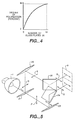
- Figure 4 shows the relationship between the number of glass plates 20 indicated along the abscissa and the degree of polarisation indicated along the ordinate as obtained by actual measurements. About an 80% degree of polarisation can be achieved with eight to ten glass plates, with about 30% of the S-polarised light component being absorbed, whereby a temperature rise of the polariser can be minimised.
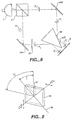
- Figure 5 shows a device in which light reflectors are used as the polarisation direction converter 3.
- the polarising beam splitter 2 separates light from the light source 1 into a P-polarised light component being transmitted light, and an S-polarised light component being reflected light.
- the travelling direction and the polarising direction of the P-polarised light are converted by light reflectors 23 and 24.
- the travelling direction of the S-polarised light component is changed by light reflectors 25 and 26.
- the two light components travel substantially in the same direction and in parallel and are converted into polarised light in the same polarising direction, to be irradiated in parallel.
- the polarised light which is separated into P- and S-polarised light components can be emitted substantially in parallel by orienting the travelling direction and the polarisation direction by means of a combination of geometric optical reflective direction characteristics. Both of the polarised light components are illuminated separately on a respective half of the aperture of the liquid crystal light valve 8, as shown in Figure 5.
- the cubic polariser or a glass plate polariser may be selected as the polarising beam splitter 2.
- the above mentioned arrangement performs image formation and image projection after the parallel emission.
- the arrangement of the light reflectors can orient the emitted light into a P-polarised light component and can select between vertical parallel emitted light or horizontal parallel emitted light.
- Figure 6 is a diagram showing another converter using a ⁇ /4 plate as the polarisation direction converter 3.
- the polarising beam splitter 2 separates emitted light from the light source into a P-polarised light component being transmitted light and an S-polarised light component being reflected light.
- the ⁇ /4 plate 27 transmits the P-polarised light component, converting the straight polarised light into circular polarised light.
- Front reflection means 28 reflect the circular polarised light to reverse its propagation direction. Then, the light is re-converted into straight polarised light by being re-transmitted into the ⁇ /4 plate 27.
- the light is thus converted into an S-polarised light component, which is perpendicular to the polarised light first entering into the ⁇ /4 plate 27, and then goes back to the polarising beam splitter 2.
- the S-polarised light component which is returned to the polarising beam splitter 2 is deflected at the reflective surface of the polarising beam splitter 2 and then passes to a wedge type light reflector 31 after repeated reflection at reflection means 29 and 30.
- the S-polarised light component which is initially reflected at the reflective surface of the polarising beam splitter 2 is symmetrically reflected with respect to the foregoing S-polarised light component transmitted through the ⁇ /4 plate about the light axis of the light source by further reflection means 29 and 30.
- the S-polarised light component then passes to the wedge type light reflector 31 and is deflected by the wedge type light reflector 31 together with the above mentioned converted S-polarised light component to be emitted substantially in parallel, and they are illuminated separately onto the aperture of the liquid crystal light valve 8.
- the wedge type light reflector 31 has a wedge type body formed of a metal, such as aluminium or stainless steel, and a high reflection mirror coating, such as a metal coating and a dielectric laminated coating layer, formed on the surface of the body.
- Figure 7 is a diagram illustrating the principle of the ⁇ /4 plate 27.
- an angle S which is made by the polarised light plane 32 of the incident light and the crystal light axis 33 of the ⁇ /4 plate 27, is 45°, the ⁇ /4 plate 27 converts incident straight polarised light into circular polarised light, or vice versa.
- Figure 8 shows another converter using a ⁇ /2 plate as the polarisation direction converter 3.
- the polarising beam splitter 2 separates the light from the light source 1 into a P-polarised light component being transmitted light and an S-polarised light component being reflected light.
- a light reflector 34 deflects the reflected S-polarised light component to a ⁇ /2 plate 35, which rotates the polarised light surface through 90° to produce a P-polarised light component for transmission to a wedge type light reflector 36.
- another light reflector 34 deflects the transmitted P-polarised light component to the wedge type light reflector 36.
- the wedge type light reflector 36 irradiates the two P-polarised light components substantially in parallel and separately to the aperture of the liquid crystal light valve 8.
- the ⁇ /2 plate 35 may also be arranged in the light path of the S-polarised light component entering the light reflector 34. Alternatively, it may be arranged in the light path of the P-polarised light component entering or leaving the other light reflector 34, if an S-polarised light component is to be supplied to the liquid crystal light valve 8.
- the wedge type light reflector 36 is used in a similar manner to that of the converter of Figure 6. In both cases, the length of the light path from the polarising beam splitter 2 to the liquid crystal light valve 8 is substantially equal for both the polarised light components.
- both of the wedge type light reflectors 31 and 36 enable a substantially equal and shortest length of light path to be realised, whereby to prevent an occurrence of a split between the two oriented light components. Therefore, the wedge type light reflector is effectively utilised to realise a bright projected picture image with reduced unevenness.
- Figure 9 is a diagram showing the principle of the ⁇ /2 plate 35.
- the angle S which is made by the polarised light plane 37 of the incident light and the crystal light axis 38 of the ⁇ /2 plate is 45°
- the ⁇ /2 plate 35 rotates the polarisation plane of the incident polarised light through 90° so that the P- (or S-) polarised light component is converted into an S-(or P-) polarised light component.
- FIG 10 is a diagram showing another arrangement, not part of the invention, using the ⁇ /2 plate 35 as the polarisation direction converter 3.
- the polarising beam splitter 2 separates the light from the light source 1 into a P-polarised light component being transmitted light and an S-polarised light component being reflected light.
- a light reflector 39 deflects the S-polarised light component to the ⁇ /2 plate 35.
- the ⁇ /2 plate 35 rotates the polarised light plane through 90° to convert it into a P-polarised light component which travels straight ahead to the liquid crystal light valve 8.
- a light reflector 40 also reflects the P-polarised light component from the polarising beam splitter 2 to the aperture of the liquid crystal light valve 8.
- the P-polarised light components are irradiated together in parallel and without any space between them in the same direction.
- the ⁇ /2 plate 35 may be arranged either in front of the light reflector 39, or in front or to the rear of the light reflector 40.
- FIG 11 is a diagram showing an embodiment of a polarisation direction converter in accordance with the present invention using a ⁇ /2 plate 35 as the polarisation direction converter 3.
- the polarising beam splitter 2 separates the light from the light source 1 into a P-polarised light component being transmitted light and an S-polarised light component being reflected light.
- the ⁇ /2 plate 35 is arranged close to the polarising beam splitter 2.
- the transmitted P-polarised light component is rotated through 90° after passing through the ⁇ /2 plate 35 so that it is converted into an S-polarised light component travelling straight ahead.
- the S-polarised light component reflected by the polarising beam splitter 2 is reflected by a light reflector 41 in the same direction as that of the other S-polarised light component, whereby the two S-polarised light components are separately projected substantially in parallel and without any space between them onto the aperture of the liquid crystal light valve 8.
- Figure 12 shows a further embodiment in which a combination of a convex lens 42 and a concave lens 43 is arranged immediately after the polarisation direction converter 3 shown in Figure 11.
- This configuration can be applied similarly in the other embodiment.
- the vertical cross sectional area of the light emitted in parallel from the polarisation direction converter 3 is approximately twice that of the light from the light source 1. Therefore, in order to utilise the light from the light source 1 effectively, the aperture area of the liquid crystal light valve 8 is required to be enlarged to be nearly twice as large as the vertical cross sectional area of the light emitted from the light source 1.
- the present embodiment may provide a bright and compact liquid crystal display device by employing a smaller liquid crystal light valve in combination with a larger light source.
- the parallel light emitted by the polarisation direction converter 3 is condensed by the convex lens 42 and re-converted to a parallel beam by the concave lens 43, so that the light from the concave lens 43 is changed into a parallel light with a small cross sectional area by comparison with that of the light entering the convex lens 42 and can be irradiated separately onto the liquid crystal light valve 8.
- the aspect ratio of the liquid crystal light valve 8 is 4:3 or 16:9 in the above mentioned embodiments the longer the sideways aperture the liquid crystal light valve 8 has, the more the half-separating irradiation shows notable effect.
- the half-separation irradiation of the present invention provides an improved illumination ratio for the picture image as well as a brighter picture image.
- the light source 1 and the polariser 14 are arranged at a proper distance so that the polariser 14 is outside the influence of heat from the light source 1 on the absorption of the polarised light component.
- a low revolution type cooling fan can provide stable reliability for the device under a wide range of ambient temperatures. Therefore, a high revolution type cooling fan with high cooling capability is not required. With respect to the temperature condition, it is preferable to remove the polariser 14.
- a projection type liquid crystal display device is constructed such that light emitted from a light source is separated into a P-polarised light component and an S-polarised light component by a polarising beam splitter, both of the polarised light components are directed in the same polarising direction and substantially in parallel, and a picture image is projected by separately projecting the components onto the aperture of a liquid crystal light valve, whereby most of the light sent from the light source can be incident onto the aperture of the liquid crystal light valve and a high intensity picture image can be realised by utilising the maximum light flux from the light source.
Landscapes
- Engineering & Computer Science (AREA)
- Physics & Mathematics (AREA)
- Multimedia (AREA)
- Signal Processing (AREA)
- General Physics & Mathematics (AREA)
- Business, Economics & Management (AREA)
- Marketing (AREA)
- Accounting & Taxation (AREA)
- Theoretical Computer Science (AREA)
- Chemical & Material Sciences (AREA)
- Crystallography & Structural Chemistry (AREA)
- Liquid Crystal (AREA)
- Projection Apparatus (AREA)
- Transforming Electric Information Into Light Information (AREA)
- Devices For Indicating Variable Information By Combining Individual Elements (AREA)
Applications Claiming Priority (4)
| Application Number | Priority Date | Filing Date | Title |
|---|---|---|---|
| JP26088289 | 1989-10-05 | ||
| JP1260882A JP2893599B2 (ja) | 1989-10-05 | 1989-10-05 | 偏光光源及び投写型表示装置 |
| JP260882/89 | 1989-10-05 | ||
| EP90310142A EP0421628B1 (de) | 1989-10-05 | 1990-09-17 | LCD-Anzeigevorrichtung vom Projektionstyp |
Related Parent Applications (2)
| Application Number | Title | Priority Date | Filing Date |
|---|---|---|---|
| EP90310142.6 Division | 1990-09-17 | ||
| EP90310142A Division EP0421628B1 (de) | 1989-10-05 | 1990-09-17 | LCD-Anzeigevorrichtung vom Projektionstyp |
Publications (2)
| Publication Number | Publication Date |
|---|---|
| EP0777146A1 true EP0777146A1 (de) | 1997-06-04 |
| EP0777146B1 EP0777146B1 (de) | 2000-11-02 |
Family
ID=17354061
Family Applications (2)
| Application Number | Title | Priority Date | Filing Date |
|---|---|---|---|
| EP90310142A Expired - Lifetime EP0421628B1 (de) | 1989-10-05 | 1990-09-17 | LCD-Anzeigevorrichtung vom Projektionstyp |
| EP97200412A Expired - Lifetime EP0777146B1 (de) | 1989-10-05 | 1990-09-17 | Projektionsanzeigevorrichtung |
Family Applications Before (1)
| Application Number | Title | Priority Date | Filing Date |
|---|---|---|---|
| EP90310142A Expired - Lifetime EP0421628B1 (de) | 1989-10-05 | 1990-09-17 | LCD-Anzeigevorrichtung vom Projektionstyp |
Country Status (4)
| Country | Link |
|---|---|
| US (2) | US5200843A (de) |
| EP (2) | EP0421628B1 (de) |
| JP (1) | JP2893599B2 (de) |
| DE (2) | DE69033658T2 (de) |
Cited By (5)
| Publication number | Priority date | Publication date | Assignee | Title |
|---|---|---|---|---|
| US5940149A (en) * | 1997-12-11 | 1999-08-17 | Minnesota Mining And Manufacturing Company | Planar polarizer for LCD projectors |
| US6104536A (en) * | 1998-09-18 | 2000-08-15 | 3M Innovative Properties Company | High efficiency polarization converter including input and output lenslet arrays |
| US8422132B2 (en) | 2008-12-02 | 2013-04-16 | Shanghai Lexvu Opto Microelectronics Technology Co., Ltd. | Integrated planar polarizing device |
| CN109584741A (zh) * | 2018-12-04 | 2019-04-05 | 深圳绿米联创科技有限公司 | 一种隐藏式屏下光学模组及电子设备 |
| WO2021008598A1 (zh) * | 2019-07-17 | 2021-01-21 | 华为技术有限公司 | 电子设备 |
Families Citing this family (108)
| Publication number | Priority date | Publication date | Assignee | Title |
|---|---|---|---|---|
| JP2752751B2 (ja) * | 1989-12-20 | 1998-05-18 | キヤノン株式会社 | 表示装置 |
| DE69028497T2 (de) * | 1989-12-20 | 1997-02-06 | Canon Kk | Polarisierendes Beleuchtungsgerät |
| US5570209A (en) * | 1990-09-18 | 1996-10-29 | Mitsubishi Denki Kabushiki Kaisha | Color projection type display apparatus having three liquid crystal displays of same structure |
| JP2575558Y2 (ja) * | 1990-12-26 | 1998-07-02 | エルジー電子株式会社 | 液晶投写形ディスプレイの光学系構造 |
| US6392689B1 (en) * | 1991-02-21 | 2002-05-21 | Eugene Dolgoff | System for displaying moving images pseudostereoscopically |
| JP3039570B2 (ja) * | 1991-06-24 | 2000-05-08 | キヤノン株式会社 | 投写表示装置 |
| US5311217A (en) * | 1991-12-23 | 1994-05-10 | Xerox Corporation | Variable attenuator for dual beams |
| US5864326A (en) | 1992-02-07 | 1999-01-26 | I-O Display Systems Llc | Depixelated visual display |
| US6097543A (en) | 1992-02-07 | 2000-08-01 | I-O Display Systems Llc | Personal visual display |
| US5303085A (en) | 1992-02-07 | 1994-04-12 | Rallison Richard D | Optically corrected helmet mounted display |
| JPH05241103A (ja) * | 1992-02-21 | 1993-09-21 | Nec Corp | 投射型液晶表示装置 |
| US5903388A (en) * | 1992-06-11 | 1999-05-11 | Sedlmayr Steven R | High efficiency electromagnetic beam projector and systems and method for implementation thereof |
| SE501987C2 (sv) * | 1992-09-11 | 1995-07-10 | Tunnelvision Ab | Förfarande att åstadkomma visning av bilder utvändigt om fordon samt medel härför |
| TW594115B (en) * | 1992-10-09 | 2004-06-21 | Asahi Glass Co Ltd | A liquid crystal display device and an illumination device for a direct viewing type display element |
| USRE37377E1 (en) * | 1992-10-09 | 2001-09-18 | Asahi Glass Company, Ltd. | LCD device including an illumination device having a polarized light separating sheet between a light guide and the display |
| EP0601628B1 (de) * | 1992-12-02 | 1998-03-18 | Koninklijke Philips Electronics N.V. | Optisches Projektionsgerät |
| JPH06222212A (ja) * | 1992-12-03 | 1994-08-12 | Matsushita Electric Ind Co Ltd | 偏波面回転光学装置及び偏光変換光学装置及び投写型表示装置 |
| US5526022A (en) | 1993-01-06 | 1996-06-11 | Virtual I/O, Inc. | Sourceless orientation sensor |
| US5594561A (en) * | 1993-03-31 | 1997-01-14 | Palomar Technologies Corporation | Flat panel display with elliptical diffuser and fiber optic plate |
| JP3168765B2 (ja) * | 1993-04-01 | 2001-05-21 | 松下電器産業株式会社 | 偏光装置および該偏光装置を用いた投写型表示装置 |
| US5621551A (en) * | 1993-04-30 | 1997-04-15 | Hughes-Jvc Technology Corporation | Immersed dichroic system for single projection lens liquid crystal video projector |
| US5512967A (en) * | 1993-09-28 | 1996-04-30 | Proxima Corporation | Projector |
| DE4435450A1 (de) * | 1993-10-04 | 1995-04-06 | Matsushita Electric Industrial Co Ltd | Flüssigkristalleinheit und Projektionsanzeige unter Verwendung einer Flüssigkristalleinheit |
| US5748828A (en) * | 1993-11-10 | 1998-05-05 | Alliedsignal Inc. | Color separating backlight |
| US5991087A (en) | 1993-11-12 | 1999-11-23 | I-O Display System Llc | Non-orthogonal plate in a virtual reality or heads up display |
| AU1866395A (en) * | 1993-12-21 | 1995-07-10 | Minnesota Mining And Manufacturing Company | Multilayered optical film |
| US6025897A (en) | 1993-12-21 | 2000-02-15 | 3M Innovative Properties Co. | Display with reflective polarizer and randomizing cavity |
| US5828488A (en) * | 1993-12-21 | 1998-10-27 | Minnesota Mining And Manufacturing Co. | Reflective polarizer display |
| US5882774A (en) * | 1993-12-21 | 1999-03-16 | Minnesota Mining And Manufacturing Company | Optical film |
| US6096375A (en) * | 1993-12-21 | 2000-08-01 | 3M Innovative Properties Company | Optical polarizer |
| US20070091230A1 (en) * | 1993-12-21 | 2007-04-26 | 3M Innovative Properties Company | Display incorporating reflective polarizer |
| US6804058B1 (en) | 1993-12-21 | 2004-10-12 | 3M Innovative Properties Company | Electroluminescent light source and display incorporating same |
| AU2156295A (en) * | 1994-02-07 | 1995-08-21 | Virtual I/O, Inc. | Personal visual display |
| US6160666A (en) | 1994-02-07 | 2000-12-12 | I-O Display Systems Llc | Personal visual display system |
| US6101032A (en) | 1994-04-06 | 2000-08-08 | 3M Innovative Properties Company | Light fixture having a multilayer polymeric film |
| US5600487A (en) * | 1994-04-14 | 1997-02-04 | Omron Corporation | Dichroic mirror for separating/synthesizing light with a plurality of wavelengths and optical apparatus and detecting method using the same |
| JPH07294850A (ja) * | 1994-04-22 | 1995-11-10 | Canon Inc | 照明装置及びそれを用いた投影装置 |
| DE69535145T2 (de) * | 1994-06-01 | 2007-06-14 | Koninklijke Philips Electronics N.V. | Beleuchtungsgerät mit hohem wirkungsgrad und dieses gerät enthaltende projektionseinrichtung |
| US5903395A (en) | 1994-08-31 | 1999-05-11 | I-O Display Systems Llc | Personal visual display system |
| JP3219943B2 (ja) * | 1994-09-16 | 2001-10-15 | 株式会社東芝 | 平面直視型表示装置 |
| US5808800A (en) * | 1994-12-22 | 1998-09-15 | Displaytech, Inc. | Optics arrangements including light source arrangements for an active matrix liquid crystal image generator |
| WO1996020424A1 (fr) * | 1994-12-27 | 1996-07-04 | Seiko Epson Corporation | Visuel du type a projection |
| EP1063554B1 (de) * | 1994-12-28 | 2004-03-03 | Seiko Epson Corporation | Polarisations-Beleuchtungsvorrichtung und diese verwendender Projektor |
| US5991085A (en) | 1995-04-21 | 1999-11-23 | I-O Display Systems Llc | Head-mounted personal visual display apparatus with image generator and holder |
| US5757547A (en) * | 1995-04-24 | 1998-05-26 | Polycom, Inc. | High efficiency homogeneous polarization converter |
| JPH08339710A (ja) * | 1995-06-12 | 1996-12-24 | Nikon Corp | 光源装置 |
| US5686979A (en) * | 1995-06-26 | 1997-11-11 | Minnesota Mining And Manufacturing Company | Optical panel capable of switching between reflective and transmissive states |
| US5608552A (en) * | 1995-12-26 | 1997-03-04 | Hughes Electronics | Liquid crystal display having an off-axis full-color holographic filter |
| TW401530B (en) * | 1996-03-12 | 2000-08-11 | Seiko Epson Corp | Polarized light separation device, method of fabricating the same and projection display apparatus using the polarized light separation device |
| US6049403A (en) * | 1996-07-25 | 2000-04-11 | Delta America Ltd. | V-splitter for optical engine |
| JP3473335B2 (ja) | 1996-08-19 | 2003-12-02 | セイコーエプソン株式会社 | 投写型表示装置 |
| CN101256340A (zh) * | 1996-08-19 | 2008-09-03 | 精工爱普生株式会社 | 投影式显示装置 |
| JP3791130B2 (ja) * | 1996-08-19 | 2006-06-28 | セイコーエプソン株式会社 | 投写型表示装置 |
| JP2894290B2 (ja) * | 1996-08-20 | 1999-05-24 | 日本電気株式会社 | 投射型カラー液晶表示装置 |
| US5975703A (en) * | 1996-09-30 | 1999-11-02 | Digital Optics International | Image projection system |
| US6356322B1 (en) * | 1996-09-30 | 2002-03-12 | Fuji Photo Film Co., Ltd. | Liquid crystal display system with improved contrast and less dependence on visual angle |
| JPH10186282A (ja) * | 1996-11-11 | 1998-07-14 | Sharp Corp | 投影型画像表示装置 |
| US6249378B1 (en) * | 1997-02-28 | 2001-06-19 | Nikon Corporation | Mirror and projection type display apparatus |
| US5973833A (en) * | 1997-08-29 | 1999-10-26 | Lightware, Inc. | High efficiency polarizing converter |
| US5903396A (en) | 1997-10-17 | 1999-05-11 | I/O Display Systems, Llc | Intensified visual display |
| US7023602B2 (en) | 1999-05-17 | 2006-04-04 | 3M Innovative Properties Company | Reflective LCD projection system using wide-angle Cartesian polarizing beam splitter and color separation and recombination prisms |
| US6486997B1 (en) | 1997-10-28 | 2002-11-26 | 3M Innovative Properties Company | Reflective LCD projection system using wide-angle Cartesian polarizing beam splitter |
| JP3808992B2 (ja) * | 1997-11-21 | 2006-08-16 | 三菱電機株式会社 | 液晶パネルモジュール |
| JP3614001B2 (ja) * | 1997-12-03 | 2005-01-26 | セイコーエプソン株式会社 | 投影装置 |
| US6808658B2 (en) * | 1998-01-13 | 2004-10-26 | 3M Innovative Properties Company | Method for making texture multilayer optical films |
| JP2002508092A (ja) * | 1998-04-02 | 2002-03-12 | コーニンクレッカ フィリップス エレクトロニクス エヌ ヴィ | 増強された輝度を有する画像投射装置 |
| US6108131A (en) | 1998-05-14 | 2000-08-22 | Moxtek | Polarizer apparatus for producing a generally polarized beam of light |
| JP2000206613A (ja) * | 1999-01-11 | 2000-07-28 | Sony Corp | 投射型表示装置 |
| US6995917B1 (en) | 1999-04-08 | 2006-02-07 | Sharp Laboratories Of America, Inc. | Projection display system using polarized light |
| WO2001013079A1 (en) * | 1999-08-18 | 2001-02-22 | Swinburne University | Method and apparatus for the resolution of beams of electromagnetic radiation |
| AU8007800A (en) * | 1999-10-08 | 2001-04-23 | Digilens Inc. | Projection display employing switchable holographic optical elements |
| US6424437B1 (en) | 2000-10-10 | 2002-07-23 | Digilens, Inc. | Projection display employing switchable holographic optical elements |
| US6783812B2 (en) | 2000-12-15 | 2004-08-31 | Displaytech, Inc. | Alkyl silane liquid crystal compounds |
| US6737124B2 (en) | 2000-12-15 | 2004-05-18 | Displaytech, Inc. | Liquid crystal compounds having a silane tail with a perfluoroalkyl terminal portion |
| US7195719B1 (en) | 2001-01-03 | 2007-03-27 | Displaytech, Inc. | High polarization ferroelectric liquid crystal compositions |
| US6838128B1 (en) | 2002-02-05 | 2005-01-04 | Displaytech, Inc. | High polarization dopants for ferroelectric liquid crystal compositions |
| TWI289708B (en) * | 2002-12-25 | 2007-11-11 | Qualcomm Mems Technologies Inc | Optical interference type color display |
| TW594053B (en) * | 2003-03-25 | 2004-06-21 | Delta Electronics Inc | Image projection apparatus and its optical polarization module |
| US8164721B2 (en) | 2003-12-11 | 2012-04-24 | Tan Kim L | Grating trim retarders |
| US7626661B2 (en) * | 2003-12-11 | 2009-12-01 | Jds Uniphase Corporation | Polarization controlling elements |
| US7342705B2 (en) | 2004-02-03 | 2008-03-11 | Idc, Llc | Spatial light modulator with integrated optical compensation structure |
| US20060132383A1 (en) * | 2004-09-27 | 2006-06-22 | Idc, Llc | System and method for illuminating interferometric modulator display |
| US7630123B2 (en) * | 2004-09-27 | 2009-12-08 | Qualcomm Mems Technologies, Inc. | Method and device for compensating for color shift as a function of angle of view |
| US20060066586A1 (en) * | 2004-09-27 | 2006-03-30 | Gally Brian J | Touchscreens for displays |
| JP4903407B2 (ja) * | 2005-08-29 | 2012-03-28 | Necディスプレイソリューションズ株式会社 | 投射型表示装置の光の調整方法 |
| US7896489B2 (en) * | 2005-11-02 | 2011-03-01 | Fujifilm Corporation | Image recording apparatus |
| PT2067066E (pt) * | 2006-09-29 | 2015-02-03 | Reald Inc | Sistemas de conversão de polarização para projeção estereoscópica |
| WO2008045200A2 (en) * | 2006-10-06 | 2008-04-17 | Qualcomm Mems Technologies, Inc. | Optical loss structure integrated in an illumination apparatus of a display |
| WO2008045207A2 (en) | 2006-10-06 | 2008-04-17 | Qualcomm Mems Technologies, Inc. | Light guide |
| WO2008045462A2 (en) * | 2006-10-10 | 2008-04-17 | Qualcomm Mems Technologies, Inc. | Display device with diffractive optics |
| US7857455B2 (en) * | 2006-10-18 | 2010-12-28 | Reald Inc. | Combining P and S rays for bright stereoscopic projection |
| CA2686928C (en) | 2007-05-09 | 2016-10-11 | Reald | Polarization conversion system and method for stereoscopic projection |
| US7949213B2 (en) * | 2007-12-07 | 2011-05-24 | Qualcomm Mems Technologies, Inc. | Light illumination of displays with front light guide and coupling elements |
| US8068710B2 (en) | 2007-12-07 | 2011-11-29 | Qualcomm Mems Technologies, Inc. | Decoupled holographic film and diffuser |
| US20090168459A1 (en) * | 2007-12-27 | 2009-07-02 | Qualcomm Incorporated | Light guide including conjugate film |
| US8721149B2 (en) | 2008-01-30 | 2014-05-13 | Qualcomm Mems Technologies, Inc. | Illumination device having a tapered light guide |
| US8348489B2 (en) * | 2008-01-30 | 2013-01-08 | Qualcomm Mems Technologies, Inc. | Thin illumination system |
| CN102449513B (zh) * | 2009-05-29 | 2015-01-21 | 高通Mems科技公司 | 照明装置及其制造方法 |
| WO2011014207A1 (en) * | 2009-07-31 | 2011-02-03 | University Of Utah Research Foundation | Beam splitter module |
| US8902484B2 (en) | 2010-12-15 | 2014-12-02 | Qualcomm Mems Technologies, Inc. | Holographic brightness enhancement film |
| JP5910031B2 (ja) * | 2011-11-28 | 2016-04-27 | ソニー株式会社 | 投影装置 |
| JP5906692B2 (ja) * | 2011-11-29 | 2016-04-20 | セイコーエプソン株式会社 | 表示装置 |
| WO2015073838A1 (en) | 2013-11-15 | 2015-05-21 | Reald Inc. | High dynamic range, high contrast projection systems |
| US9851575B2 (en) * | 2014-05-15 | 2017-12-26 | Omnivision Technologies, Inc. | Wafer-level liquid-crystal-on-silicon projection assembly, systems and methods |
| KR20160147636A (ko) * | 2015-06-15 | 2016-12-23 | 삼성전자주식회사 | 헤드 마운티드 디스플레이 장치 |
| WO2016204433A1 (en) * | 2015-06-15 | 2016-12-22 | Samsung Electronics Co., Ltd. | Head mounted display apparatus |
| EP3465336B1 (de) * | 2016-06-03 | 2020-09-30 | Gentex Corporation | Anzeigesystem mit phasenausgerichteter reflektierender steuerung |
| CN115542639A (zh) * | 2021-06-11 | 2022-12-30 | 中兴通讯股份有限公司 | 屏下摄像显示装置及其控制方法、控制器和终端设备 |
Citations (7)
| Publication number | Priority date | Publication date | Assignee | Title |
|---|---|---|---|---|
| US4127322A (en) * | 1975-12-05 | 1978-11-28 | Hughes Aircraft Company | High brightness full color image light valve projection system |
| EP0083440A2 (de) * | 1981-12-28 | 1983-07-13 | Hughes Aircraft Company | System für zweifarbige Bildprojektion durch Lichtventile aus flüssigem Kristall mit Vorpolarisation |
| JPS63121821A (ja) | 1986-11-12 | 1988-05-25 | Hitachi Ltd | 液晶表示装置 |
| US4749259A (en) * | 1987-05-15 | 1988-06-07 | Hughes Aircraft Company | Liquid crystal image projection with multicolor prepolarizing system |
| JPS63168622A (ja) * | 1987-01-05 | 1988-07-12 | Canon Inc | 光偏向素子 |
| JPS63185188A (ja) | 1987-01-27 | 1988-07-30 | Canon Inc | Lcdプロジエクタ装置 |
| US4913529A (en) * | 1988-12-27 | 1990-04-03 | North American Philips Corp. | Illumination system for an LCD display system |
Family Cites Families (31)
| Publication number | Priority date | Publication date | Assignee | Title |
|---|---|---|---|---|
| US4425028A (en) * | 1981-12-28 | 1984-01-10 | Hughes Aircraft Company | High efficiency optical tank for three color liquid crystal light valve image projection with color selective prepolarization and single projection lens |
| US4500172A (en) * | 1981-12-28 | 1985-02-19 | Hughes Aircraft Company | Two color liquid crystal light valve image projection system with single prepolarizer |
| JPS59201026A (ja) * | 1983-04-30 | 1984-11-14 | Fujitsu Ltd | 偏光素子 |
| US4516837A (en) * | 1983-02-22 | 1985-05-14 | Sperry Corporation | Electro-optical switch for unpolarized optical signals |
| JPS61145503A (ja) * | 1984-12-20 | 1986-07-03 | Fujitsu Ltd | 光分離合成用プリズム |
| JPS6211823A (ja) * | 1985-07-10 | 1987-01-20 | Mitsubishi Electric Corp | 偏光変換器 |
| FR2584843B1 (fr) * | 1985-07-12 | 1989-02-24 | Sfena | Appareil de visualisation a champ etendu dans lequel l'image est formee par la juxtaposition d'au moins deux images partielles |
| JPS6215518A (ja) * | 1985-07-15 | 1987-01-23 | Mitsubishi Electric Corp | 偏光変換器 |
| US4690526A (en) * | 1985-09-12 | 1987-09-01 | Hughes Aircraft Company | Prism assembly for a single light valve full-color projector |
| JPH0792561B2 (ja) * | 1986-07-08 | 1995-10-09 | 株式会社精工舎 | 投写式液晶表示装置 |
| JPS6315219A (ja) * | 1986-07-08 | 1988-01-22 | Seikosha Co Ltd | 投写式液晶表示装置 |
| US4864390A (en) * | 1986-08-22 | 1989-09-05 | North American Philips Corporation | Display system with equal path lengths |
| JPS63123018A (ja) * | 1986-11-12 | 1988-05-26 | Hitachi Ltd | 投射型液晶表示装置 |
| US4989076A (en) * | 1987-01-27 | 1991-01-29 | Canon Kabushiki Kaisha | Video projection apparatus |
| US4786146A (en) * | 1987-02-11 | 1988-11-22 | Hughes Aircraft Company | Color sequential illumination system for a liquid crystal light valve |
| JP2691530B2 (ja) * | 1987-03-04 | 1997-12-17 | セイコーエプソン株式会社 | 投写型カラー表示装置 |
| DE3852776T2 (de) * | 1987-04-14 | 1995-06-22 | Seiko Epson Corp | Projektions-Farbflüssigkristall-Anzeigevorrichtung. |
| JPS63271313A (ja) * | 1987-04-30 | 1988-11-09 | Nikon Corp | 偏光器 |
| DE3720375A1 (de) * | 1987-06-19 | 1988-12-29 | Fraunhofer Ges Forschung | Projektionsvorrichtung |
| JPH0830789B2 (ja) * | 1987-08-19 | 1996-03-27 | 富士通株式会社 | 偏光分離合成プリズム |
| JPH0218825A (ja) * | 1988-07-07 | 1990-01-23 | Toshiba Corp | ガス遮断器 |
| GB8816983D0 (en) * | 1988-07-16 | 1988-08-17 | Jaguar Cars | Pistons |
| GB8816981D0 (en) * | 1988-07-16 | 1988-08-17 | Jaguar Cars | Pistons |
| JP2629871B2 (ja) * | 1988-08-29 | 1997-07-16 | スズキ株式会社 | 車両用変速機 |
| JPH0262475A (ja) * | 1988-08-29 | 1990-03-02 | Tokyo Sokuhan Co Ltd | 自動変速機付車両の速度制御装置 |
| JP2730734B2 (ja) * | 1988-08-30 | 1998-03-25 | マツダ株式会社 | 自動変速機搭載車のエンジン出力制御装置 |
| JPH0264613A (ja) * | 1988-08-31 | 1990-03-05 | Seiko Epson Corp | 偏光光源 |
| JP2874163B2 (ja) * | 1988-09-06 | 1999-03-24 | セイコーエプソン株式会社 | 偏光光源、液晶表示装置及び投射型表示装置 |
| US5042921A (en) * | 1988-10-25 | 1991-08-27 | Casio Computer Co., Ltd. | Liquid crystal display apparatus |
| JPH02153336A (ja) * | 1988-12-05 | 1990-06-13 | Sharp Corp | 投影型液晶表示装置 |
| JP2800271B2 (ja) * | 1989-06-07 | 1998-09-21 | カシオ計算機株式会社 | 液晶表示装置 |
-
1989
- 1989-10-05 JP JP1260882A patent/JP2893599B2/ja not_active Expired - Lifetime
-
1990
- 1990-09-17 DE DE69033658T patent/DE69033658T2/de not_active Expired - Lifetime
- 1990-09-17 EP EP90310142A patent/EP0421628B1/de not_active Expired - Lifetime
- 1990-09-17 EP EP97200412A patent/EP0777146B1/de not_active Expired - Lifetime
- 1990-09-17 DE DE69031773T patent/DE69031773T2/de not_active Expired - Lifetime
- 1990-10-05 US US07/593,107 patent/US5200843A/en not_active Expired - Lifetime
-
1992
- 1992-10-30 US US07/968,696 patent/US5278680A/en not_active Expired - Lifetime
Patent Citations (7)
| Publication number | Priority date | Publication date | Assignee | Title |
|---|---|---|---|---|
| US4127322A (en) * | 1975-12-05 | 1978-11-28 | Hughes Aircraft Company | High brightness full color image light valve projection system |
| EP0083440A2 (de) * | 1981-12-28 | 1983-07-13 | Hughes Aircraft Company | System für zweifarbige Bildprojektion durch Lichtventile aus flüssigem Kristall mit Vorpolarisation |
| JPS63121821A (ja) | 1986-11-12 | 1988-05-25 | Hitachi Ltd | 液晶表示装置 |
| JPS63168622A (ja) * | 1987-01-05 | 1988-07-12 | Canon Inc | 光偏向素子 |
| JPS63185188A (ja) | 1987-01-27 | 1988-07-30 | Canon Inc | Lcdプロジエクタ装置 |
| US4749259A (en) * | 1987-05-15 | 1988-06-07 | Hughes Aircraft Company | Liquid crystal image projection with multicolor prepolarizing system |
| US4913529A (en) * | 1988-12-27 | 1990-04-03 | North American Philips Corp. | Illumination system for an LCD display system |
Non-Patent Citations (3)
| Title |
|---|
| PATENT ABSTRACTS OF JAPAN vol. 012, no. 370 (P - 767)<3217> 5 October 1988 (1988-10-05) * |
| PATENT ABSTRACTS OF JAPAN vol. 012, no. 439 (P - 788) 18 November 1988 (1988-11-18) * |
| PATENT ABSTRACTS OF JAPAN vol. 012, no. 461 (E - 689) 5 December 1988 (1988-12-05) * |
Cited By (5)
| Publication number | Priority date | Publication date | Assignee | Title |
|---|---|---|---|---|
| US5940149A (en) * | 1997-12-11 | 1999-08-17 | Minnesota Mining And Manufacturing Company | Planar polarizer for LCD projectors |
| US6104536A (en) * | 1998-09-18 | 2000-08-15 | 3M Innovative Properties Company | High efficiency polarization converter including input and output lenslet arrays |
| US8422132B2 (en) | 2008-12-02 | 2013-04-16 | Shanghai Lexvu Opto Microelectronics Technology Co., Ltd. | Integrated planar polarizing device |
| CN109584741A (zh) * | 2018-12-04 | 2019-04-05 | 深圳绿米联创科技有限公司 | 一种隐藏式屏下光学模组及电子设备 |
| WO2021008598A1 (zh) * | 2019-07-17 | 2021-01-21 | 华为技术有限公司 | 电子设备 |
Also Published As
| Publication number | Publication date |
|---|---|
| JPH03122631A (ja) | 1991-05-24 |
| EP0421628A2 (de) | 1991-04-10 |
| EP0421628B1 (de) | 1997-12-03 |
| US5278680A (en) | 1994-01-11 |
| DE69033658T2 (de) | 2001-03-01 |
| EP0421628A3 (en) | 1992-04-15 |
| DE69031773T2 (de) | 1998-03-26 |
| JP2893599B2 (ja) | 1999-05-24 |
| DE69031773D1 (de) | 1998-01-15 |
| EP0777146B1 (de) | 2000-11-02 |
| US5200843A (en) | 1993-04-06 |
| DE69033658D1 (de) | 2000-12-07 |
Similar Documents
| Publication | Publication Date | Title |
|---|---|---|
| EP0777146B1 (de) | Projektionsanzeigevorrichtung | |
| US7452086B2 (en) | Light pipe based projection engine | |
| US5267029A (en) | Image projector | |
| US5153752A (en) | Projector | |
| US6154320A (en) | Polarizing conversion device, polarizing illuminations device, and display apparatus and projector using the devices | |
| USRE39951E1 (en) | Polarization conversion element, polarization illuminator, display using the same illuminator, and projector | |
| JPH08271854A (ja) | 光源の像を投写する装置 | |
| JPH08292411A (ja) | 光源により生成された像を投写する装置 | |
| US6152566A (en) | Projector for modulating polarized luminous flux | |
| KR20010021101A (ko) | 프로젝터 | |
| JPH068985B2 (ja) | 投写型表示装置 | |
| EP0435288B1 (de) | Bildprojektor | |
| JPH11202432A (ja) | 投射型画像表示装置 | |
| JP3335885B2 (ja) | 偏光照明装置、および投写型液晶表示装置 | |
| JP4247042B2 (ja) | 投写型表示装置 | |
| JP3336794B2 (ja) | 偏光照明装置およびそれを用いた投写型表示装置 | |
| KR100327197B1 (ko) | 색균일도를개선한액정프로젝터 | |
| JPH0772428A (ja) | 投写型液晶表示装置の偏光光源装置 | |
| JPH1039258A (ja) | 単一偏光変換素子及び投射型表示装置 | |
| US6365526B1 (en) | Optical illumination system and projection apparatus | |
| JP2003337375A (ja) | プロジェクタ | |
| JP4077490B2 (ja) | 投射型映像表示装置 | |
| KR100359728B1 (ko) | 액정 프로젝터의 광학 장치 | |
| JP3260821B2 (ja) | 光源装置および投影型液晶画像表示装置 | |
| JP2800812B2 (ja) | カラー画像生成ユニット |
Legal Events
| Date | Code | Title | Description |
|---|---|---|---|
| PUAI | Public reference made under article 153(3) epc to a published international application that has entered the european phase |
Free format text: ORIGINAL CODE: 0009012 |
|
| 17P | Request for examination filed |
Effective date: 19970306 |
|
| AC | Divisional application: reference to earlier application |
Ref document number: 421628 Country of ref document: EP |
|
| AK | Designated contracting states |
Kind code of ref document: A1 Designated state(s): DE FR GB NL |
|
| GRAG | Despatch of communication of intention to grant |
Free format text: ORIGINAL CODE: EPIDOS AGRA |
|
| 17Q | First examination report despatched |
Effective date: 19990921 |
|
| GRAG | Despatch of communication of intention to grant |
Free format text: ORIGINAL CODE: EPIDOS AGRA |
|
| GRAH | Despatch of communication of intention to grant a patent |
Free format text: ORIGINAL CODE: EPIDOS IGRA |
|
| GRAH | Despatch of communication of intention to grant a patent |
Free format text: ORIGINAL CODE: EPIDOS IGRA |
|
| GRAA | (expected) grant |
Free format text: ORIGINAL CODE: 0009210 |
|
| AC | Divisional application: reference to earlier application |
Ref document number: 421628 Country of ref document: EP |
|
| AK | Designated contracting states |
Kind code of ref document: B1 Designated state(s): DE FR GB NL |
|
| ET | Fr: translation filed | ||
| REF | Corresponds to: |
Ref document number: 69033658 Country of ref document: DE Date of ref document: 20001207 |
|
| PLBE | No opposition filed within time limit |
Free format text: ORIGINAL CODE: 0009261 |
|
| STAA | Information on the status of an ep patent application or granted ep patent |
Free format text: STATUS: NO OPPOSITION FILED WITHIN TIME LIMIT |
|
| 26N | No opposition filed | ||
| REG | Reference to a national code |
Ref country code: GB Ref legal event code: IF02 |
|
| PGFP | Annual fee paid to national office [announced via postgrant information from national office to epo] |
Ref country code: NL Payment date: 20090915 Year of fee payment: 20 Ref country code: GB Payment date: 20090916 Year of fee payment: 20 |
|
| PGFP | Annual fee paid to national office [announced via postgrant information from national office to epo] |
Ref country code: DE Payment date: 20090910 Year of fee payment: 20 |
|
| PGFP | Annual fee paid to national office [announced via postgrant information from national office to epo] |
Ref country code: FR Payment date: 20091012 Year of fee payment: 20 |
|
| REG | Reference to a national code |
Ref country code: NL Ref legal event code: V4 Effective date: 20100917 |
|
| REG | Reference to a national code |
Ref country code: GB Ref legal event code: PE20 Expiry date: 20100916 |
|
| PG25 | Lapsed in a contracting state [announced via postgrant information from national office to epo] |
Ref country code: GB Free format text: LAPSE BECAUSE OF EXPIRATION OF PROTECTION Effective date: 20100916 |
|
| PG25 | Lapsed in a contracting state [announced via postgrant information from national office to epo] |
Ref country code: NL Free format text: LAPSE BECAUSE OF EXPIRATION OF PROTECTION Effective date: 20100917 |
|
| PG25 | Lapsed in a contracting state [announced via postgrant information from national office to epo] |
Ref country code: DE Free format text: LAPSE BECAUSE OF EXPIRATION OF PROTECTION Effective date: 20100917 |