EP0777168A2 - Régulateur de pression pour gaz naturel - Google Patents
Régulateur de pression pour gaz naturel Download PDFInfo
- Publication number
- EP0777168A2 EP0777168A2 EP96850167A EP96850167A EP0777168A2 EP 0777168 A2 EP0777168 A2 EP 0777168A2 EP 96850167 A EP96850167 A EP 96850167A EP 96850167 A EP96850167 A EP 96850167A EP 0777168 A2 EP0777168 A2 EP 0777168A2
- Authority
- EP
- European Patent Office
- Prior art keywords
- pressure
- gas
- valving
- regulator
- valve
- Prior art date
- Legal status (The legal status is an assumption and is not a legal conclusion. Google has not performed a legal analysis and makes no representation as to the accuracy of the status listed.)
- Granted
Links
Images


Classifications
-
- F—MECHANICAL ENGINEERING; LIGHTING; HEATING; WEAPONS; BLASTING
- F17—STORING OR DISTRIBUTING GASES OR LIQUIDS
- F17C—VESSELS FOR CONTAINING OR STORING COMPRESSED, LIQUEFIED OR SOLIDIFIED GASES; FIXED-CAPACITY GAS-HOLDERS; FILLING VESSELS WITH, OR DISCHARGING FROM VESSELS, COMPRESSED, LIQUEFIED, OR SOLIDIFIED GASES
- F17C13/00—Details of vessels or of the filling or discharging of vessels
- F17C13/04—Arrangement or mounting of valves
-
- G—PHYSICS
- G05—CONTROLLING; REGULATING
- G05D—SYSTEMS FOR CONTROLLING OR REGULATING NON-ELECTRIC VARIABLES
- G05D16/00—Control of fluid pressure
- G05D16/04—Control of fluid pressure without auxiliary power
- G05D16/06—Control of fluid pressure without auxiliary power the sensing element being a flexible membrane, yielding to pressure, e.g. diaphragm, bellows, capsule
- G05D16/063—Control of fluid pressure without auxiliary power the sensing element being a flexible membrane, yielding to pressure, e.g. diaphragm, bellows, capsule the sensing element being a membrane
- G05D16/0644—Control of fluid pressure without auxiliary power the sensing element being a flexible membrane, yielding to pressure, e.g. diaphragm, bellows, capsule the sensing element being a membrane the membrane acting directly on the obturator
- G05D16/0663—Control of fluid pressure without auxiliary power the sensing element being a flexible membrane, yielding to pressure, e.g. diaphragm, bellows, capsule the sensing element being a membrane the membrane acting directly on the obturator using a spring-loaded membrane with a spring-loaded slideable obturator
-
- Y—GENERAL TAGGING OF NEW TECHNOLOGICAL DEVELOPMENTS; GENERAL TAGGING OF CROSS-SECTIONAL TECHNOLOGIES SPANNING OVER SEVERAL SECTIONS OF THE IPC; TECHNICAL SUBJECTS COVERED BY FORMER USPC CROSS-REFERENCE ART COLLECTIONS [XRACs] AND DIGESTS
- Y10—TECHNICAL SUBJECTS COVERED BY FORMER USPC
- Y10T—TECHNICAL SUBJECTS COVERED BY FORMER US CLASSIFICATION
- Y10T137/00—Fluid handling
- Y10T137/6851—With casing, support, protector or static constructional installations
- Y10T137/7036—Jacketed
-
- Y—GENERAL TAGGING OF NEW TECHNOLOGICAL DEVELOPMENTS; GENERAL TAGGING OF CROSS-SECTIONAL TECHNOLOGIES SPANNING OVER SEVERAL SECTIONS OF THE IPC; TECHNICAL SUBJECTS COVERED BY FORMER USPC CROSS-REFERENCE ART COLLECTIONS [XRACs] AND DIGESTS
- Y10—TECHNICAL SUBJECTS COVERED BY FORMER USPC
- Y10T—TECHNICAL SUBJECTS COVERED BY FORMER US CLASSIFICATION
- Y10T137/00—Fluid handling
- Y10T137/7722—Line condition change responsive valves
- Y10T137/7754—Line flow effect assisted
- Y10T137/7756—Reactor surface separated from flow by apertured partition
-
- Y—GENERAL TAGGING OF NEW TECHNOLOGICAL DEVELOPMENTS; GENERAL TAGGING OF CROSS-SECTIONAL TECHNOLOGIES SPANNING OVER SEVERAL SECTIONS OF THE IPC; TECHNICAL SUBJECTS COVERED BY FORMER USPC CROSS-REFERENCE ART COLLECTIONS [XRACs] AND DIGESTS
- Y10—TECHNICAL SUBJECTS COVERED BY FORMER USPC
- Y10T—TECHNICAL SUBJECTS COVERED BY FORMER US CLASSIFICATION
- Y10T137/00—Fluid handling
- Y10T137/7722—Line condition change responsive valves
- Y10T137/7781—With separate connected fluid reactor surface
- Y10T137/7793—With opening bias [e.g., pressure regulator]
- Y10T137/7794—With relief valve
-
- Y—GENERAL TAGGING OF NEW TECHNOLOGICAL DEVELOPMENTS; GENERAL TAGGING OF CROSS-SECTIONAL TECHNOLOGIES SPANNING OVER SEVERAL SECTIONS OF THE IPC; TECHNICAL SUBJECTS COVERED BY FORMER USPC CROSS-REFERENCE ART COLLECTIONS [XRACs] AND DIGESTS
- Y10—TECHNICAL SUBJECTS COVERED BY FORMER USPC
- Y10T—TECHNICAL SUBJECTS COVERED BY FORMER US CLASSIFICATION
- Y10T137/00—Fluid handling
- Y10T137/7722—Line condition change responsive valves
- Y10T137/7781—With separate connected fluid reactor surface
- Y10T137/7793—With opening bias [e.g., pressure regulator]
- Y10T137/7822—Reactor surface closes chamber
- Y10T137/7823—Valve head in inlet chamber
- Y10T137/7826—With valve closing bias
Definitions
- This invention relates to a pressure-reducing regulator for compressed natural gas (CNG), and more particularly to an improved CNG regulator for vehicular engines.
- CNG compressed natural gas
- An object of the invention is to provide an improved regulator which meets the requirements of low or inaudible noise under a wide range of flow rates.
- a pressure-reducing regulator has a body with an inner chamber for receiving a high-pressure compressed gas and an outer chamber for receiving a low-pressure, compressed gas, valve means movably disposed and stabilized within said body controls the flow between said chambers, and diaphragm means coupled to the valve means is provided for sensing pressure in one of said chambers and effecting movement of the valve means.
- a top plan view of the regulator 10 having a bonnet 12 with a spherical plug cover 13.
- Coolant inlet port 14 and coolant outlet port 16 accommodate the inflow and discharge of a heating fluid, such as an antifreeze coolant from the vehicle coolant system.
- the temperature of the coolant which passes through the bowl of the regulator may be controlled, if desired, by a thermostat element in the outlet port line located either before or after the outlet port, according to known techniques.
- the regulator 10 has a bonnet 12, a regulator body 18, and a bowl 20.
- the bonnet 12 which is threadedly engaged with the body 18 includes the plug cover 13, a hex top screw 22, a spring button 24 for transferring the loading from the screw to a spring 26, and a porous plug 28.
- the bonnet, body, and bowl may be fabricated of aluminum and coated to prevent corrosion, or fabricated from a corrosive resistive material.
- the screw, spring button, and spring are preferrably fabricated of stainless steel for its corrosive resistant properties.
- the plug 28 is formed of polytetra-flouorethylene which is sufficient to permit atmospheric pressure to enter the bonnet, but prevents an intrusion of water such as splashing from roadways and the like.
- the regulator body 18 has an inner chamber 30 for receiving high-pressure, compressed, natural gas therewithin from a gas inlet port 32 and a connecting passageway 31.
- the body also has an outer chamber 34 for receiving low-pressure, compressed, natural gas therewithin.
- the outer chamber 34 connects with a gas outlet port 36 by means of a plastic nozzle 38 which extends into port 36 and is retained in place by means of an aluminum retaining nut 40 threadedly engaged with body 18.
- Diaphragm means 46 comprises a diaphragm insert 48, a diaphragm 50 with a peripheral rib 51, a diaphragm plate 52, and a plate nut 53.
- the diaphragm 50 and the body 18 forms a diaphragm cavity or chamber.
- the insert, plate and nut are fabricated of stainless steel for corrosion resistance, and the diaphragm is preferrably a Buna-N with dacron reinforcement.
- Rib 51 is nested in groove 42 and a bearing ring 54 surmounts the periphery of diaphragm 50.
- An aspirator hole or bypass orifice 56 communicates the gas pressure in the outlet port 36 with the side of diaphragm 50 which faces the diaphragm chamber 44 in the regulator body 18.
- the regulator body 18 has the bowl 20 attached thereto by means of a screw 58 which is screwed into a valve body 60 threadedly engaged into cylindrical sleeve portion 62 of body 18.
- An O-ring 64 is positioned between bowl 20 and body 18, and an O-ring 66 is positioned under the head of screw 58.
- O-ring 68 is positioned on a teflon back-up ring 70 of valve body 60.
- the valve body is fabricated from aluminum with a corrosion resistive coating and screw 58 is stainless steel.
- the bowl 20 includes a high rib 72 and two low ribs 74, 76 (rib 76 is shown in Fig. 3).
- the uppermost portion of rib 72 is received between splines 78 formed in the bottom of regulator body 18. The coolant which passes through the bowl is thus forced to flow by high rib 72 over lower ribs 74, 76 and around cylindrical sleeve portion 62 and out port 16.
- a cylindrical filter 80 is positioned around the inner chamber 30 to prevent any containments from entering inner chamber 30.
- Filter 80 is preferrably a sintered nylon filter to avoid corrosion.
- a plastic seat 82 and an O-ring 84 are positioned at the bottom of cylindrical sleeve portion 62.
- the seat 82 is preferrably a polyimide plastic.
- a plug bushing 86 having a taper at one end and a cylindrical interior is inserted into the tapered and cylindrical bore 88 of valve body 60.
- a valving element 90 has a central shank with a tubular body 92 on one end for containing a valving spring 94, and a valve plug 96 on the other end terminating in the diaphragm insert 48.
- the tubular body 92 has a conical top 98 connected to the central shank, the conical top 98 contacts seat 82 to separate the inner chamber 30 from the outer chamber 34.
- the valve plug 96 slidably passes through plug guide 100 which includes O-rings 102, 104.
- Guide 100 is positioned on stainless steel washer 106.
- the tapered plug bushing 86 is preferrably fabricated of a PEEK material (any other self-lubricating material of suitable strength, temperature and chemical resistance, such as Torlon polyamide-imide, may also be used), and the valving element of a heat treat hardened stainless steel (RC 37-40).
- the plug guide is brass and the washer is also stainless steel to prevent corrosion.
- the plastic nozzle 38 extends beyond the aspirator hole 56 to prevent the cold gas from the outer chamber from entering directly into the hole 56.
- This arrangement of nozzle and aspirator hole provides a pressure drop flow which helps keep the gas pressure output more uniform with increase flow rates.
- the regulator is designed to operate with compressed natural gas at 250-3600 PSIG inlet pressure and a 99-125 PSIG output pressure at a nominal 110 psig setting.
- the nozzle is made of a plastic material so that it acts as a thermal barrier between the cold outlet gas and the aluminum regulator body. This barrier protects the diaphragm from extreme cold until the engine coolant can warm the regulator.
- the nozzle is used as a way to correct regulator droop (droop is the decreasing output pressure with an increase in flow). Without the nozzle, the gas can expand as soon as it exits the bypass hole (where the nozzle is located). With the nozzle, the gas velocity and expansion (pressure drop) can be better controlled.
- the fluid dynamics with the nozzle in place create a "venturi” or "jet pump” effect, which exposes the aspirator hole to a slightly lower pressure.
- the lower pressure is communicated into the diaphragm chamber and makes the regulator "think" that the output pressure is lower than it truly is. In this respect, the diaphragm moves further down, the valve opens slightly more, and the regulated output pressure increases slightly to maintain the dynamic equilibrium. With the higher output pressure at higher flows, the regulator corrects for line pressure loss at these flows. Essentially, the regulator compensates somewhat for the system losses in the vehicle, and provides improved pressure control for the fuel system.
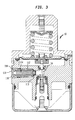
- FIG. 3 there is shown the pressure relief device for the regulator 10.
- a pressure relief port 110 is connected to outer chamber 34.
- Poppet 112 has a cylindrical interior for containing a portion of poppet stainless steel spring 114.
- a nylon poppet adjusting screw 116 is threadingly engaged in the port 110 and has a cylindrical interior to contain a portion of the poppet spring 114.
- a plastic dust cover 118 is inserted into the poppet screw. When the pressure in outer chamber 34 is greater than a predetermined amount, poppet 112 will compress spring 114 causing dust cover 118 to pop and release the gas to the atmosphere.
- the plug bushing 86 is illustrated.
- the bushing has a closed end 86a with four cylindrically shaped finger elements 86b, c, d, e formed by slots 86f, g, h, i. Although four finger elements have been used, two, three, or a multiple thereof could be used.
- the bottom interior portion of the bushing has a centrally located cone 86j for centrally positioning the valving spring.
- the four finger elements have tapered ends 86k to complimentary fit the tapered and cylindrical bore 88 (Fig. 2).
- the valve spring preloads the bushing via the tapered edge of the bushing against the bore taper of the valve body.
- the slots in the bushing allow the bushing I.D.
- the PEEK plastic material chosen for the bushing is self-lubricating and does not interfere with the regulator performance.
- the pressure regulator is designed to safely reduce the pressure of compressed natural gas (CNG) from a vehicle storage tank (up to 3600 PSIG) to a preset level which allows an engine fuel metering system to properly control the gas. This is accomplished by the pressure sensing element and controlled force moving the valve element to regulate gas flow in response to down stream pressure levels.
- CNG compressed natural gas
- the valving element provides stable flow for various operating conditions and the diaphragm provides precise sensing.
- the valving element permits controlled gas flow between the high-pressure inner chamber, and the low-pressure outer chamber, through a gap between the conical top portion of the valving element and the valve seat.
- the regulator has a coolant bowl to permit circulation of engine coolant around the valve chamber.
- the valving element movement is also stable and free of any unwelcomed low level audible noise due to its improved configuration.
- the high pressure natural gas expanding across the valve seat caused valve plug vibration resulting in emission of an audible noise.
- the inventive configuration includes a valving element 90 which has at one end a tubular body 92 enclosing a valving spring 94, the body and spring being contained within a bushing tapered at one end and inserted into the valve body. This arrangement of bushing, tubular body, and spring captured therebetween provides the stabilizing means for retaining the high pressure end of the valving element stable to prevent vibration and eliminate the low audible noises from the regulator.
Landscapes
- Physics & Mathematics (AREA)
- Engineering & Computer Science (AREA)
- Fluid Mechanics (AREA)
- General Physics & Mathematics (AREA)
- Automation & Control Theory (AREA)
- Mechanical Engineering (AREA)
- General Engineering & Computer Science (AREA)
- Control Of Fluid Pressure (AREA)
- Filling Or Discharging Of Gas Storage Vessels (AREA)
- Fluid-Driven Valves (AREA)
- Details Of Valves (AREA)
Applications Claiming Priority (2)
| Application Number | Priority Date | Filing Date | Title |
|---|---|---|---|
| US08/554,115 US5890512A (en) | 1995-11-06 | 1995-11-06 | CNG regulator |
| US554115 | 1995-11-06 |
Publications (3)
| Publication Number | Publication Date |
|---|---|
| EP0777168A2 true EP0777168A2 (fr) | 1997-06-04 |
| EP0777168A3 EP0777168A3 (fr) | 1998-04-15 |
| EP0777168B1 EP0777168B1 (fr) | 1999-12-01 |
Family
ID=24212119
Family Applications (1)
| Application Number | Title | Priority Date | Filing Date |
|---|---|---|---|
| EP96850167A Expired - Lifetime EP0777168B1 (fr) | 1995-11-06 | 1996-10-04 | Régulateur de pression pour gaz naturel |
Country Status (6)
| Country | Link |
|---|---|
| US (1) | US5890512A (fr) |
| EP (1) | EP0777168B1 (fr) |
| JP (1) | JP2931793B2 (fr) |
| KR (1) | KR100210971B1 (fr) |
| CA (1) | CA2189397C (fr) |
| DE (1) | DE69605389T2 (fr) |
Cited By (10)
| Publication number | Priority date | Publication date | Assignee | Title |
|---|---|---|---|---|
| CN1101517C (zh) * | 1998-05-20 | 2003-02-12 | 新西兰运输燃料系统有限公司 | 供气调节系统 |
| EP1593832A1 (fr) * | 2004-05-03 | 2005-11-09 | C.R.F. Società Consortile per Azioni | System d'alimentation pour un moteur à combustion interne avec régulateur de pression amélioré |
| WO2006127337A3 (fr) * | 2005-05-20 | 2007-05-03 | Itt Mfg Enterprises Inc | Regulateur de pression a perte de pression de sortie reduite |
| CN102359601A (zh) * | 2011-10-13 | 2012-02-22 | 陕西航空电气有限责任公司 | 一种过滤调整器总成 |
| ITPC20110013A1 (it) * | 2011-06-09 | 2012-12-10 | Parietti Pietro Poliauto | Dispositivo per l' alimentazione di motori con un combustibile gassoso, in particolare di motori di veicoli |
| CN102943922A (zh) * | 2012-10-24 | 2013-02-27 | 河南航天液压气动技术有限公司 | 一种减压阀 |
| RU2528220C2 (ru) * | 2009-07-02 | 2014-09-10 | Теском Корпорейшн | Уравновешенный вставной клапан |
| WO2014150341A3 (fr) * | 2013-03-15 | 2014-12-04 | Emerson Process Management Regulator Technologies, Inc. | Régulateurs de pression avec détecteurs de condition de filtre |
| CN109139302A (zh) * | 2018-11-09 | 2019-01-04 | 广西玉柴机器股份有限公司 | Cng气体机高压过滤器 |
| WO2020233949A1 (fr) * | 2019-05-17 | 2020-11-26 | Goetze KG | Soupape de réduction de pression |
Families Citing this family (38)
| Publication number | Priority date | Publication date | Assignee | Title |
|---|---|---|---|---|
| US6647982B1 (en) * | 1998-06-29 | 2003-11-18 | Zaiser Lenoir E. | Gas flow device |
| US6478046B2 (en) | 2001-01-20 | 2002-11-12 | Stanely Gabrel | Gas pressure regulator |
| DE10112962A1 (de) * | 2001-03-17 | 2002-10-02 | Hans Wiederkehr | Ventil |
| US20050011554A1 (en) * | 2003-01-28 | 2005-01-20 | Taprite-Fassco Manufacturing Inc. | Modular regulator |
| US6748932B1 (en) * | 2003-02-10 | 2004-06-15 | Chapeau, Inc. | Fuel regulator for natural gas fired co-generation unit |
| US7021329B2 (en) * | 2003-06-11 | 2006-04-04 | Itt Manufacturing Enterprises, Inc. | Vaporizing pressure regulator |
| JP4330943B2 (ja) * | 2003-06-30 | 2009-09-16 | 株式会社ジェイテクト | 水素ガス用高圧バルブ及び水素ガス用減圧装置 |
| US7165573B2 (en) * | 2003-11-25 | 2007-01-23 | Itt Manufacturing Enterprises, Inc. | Compressed natural gas pressure regulator |
| US20050257836A1 (en) * | 2004-05-18 | 2005-11-24 | Robert Boyer | Gas pressure regulator |
| EP1762709B1 (fr) * | 2005-09-13 | 2008-04-09 | Scambia Industrial Developments Aktiengesellschaft | Silencieux |
| US7418973B2 (en) * | 2005-11-08 | 2008-09-02 | Itt Manufacturing Enterprises, Inc. | Device to reduce noise in pressure regulators |
| JP4970125B2 (ja) * | 2007-04-24 | 2012-07-04 | 株式会社ケーヒン | 減圧弁 |
| US7789657B2 (en) * | 2007-10-03 | 2010-09-07 | Honeywell International Inc. | Pressure regulator with bleed orifice |
| KR100962228B1 (ko) * | 2008-04-15 | 2010-06-11 | 김성진 | 고순도용 레귤레이터 |
| US9535427B2 (en) * | 2009-01-21 | 2017-01-03 | Tescom Corporation | Temperature-controlled pressure regulators |
| US8307843B2 (en) * | 2009-01-21 | 2012-11-13 | Tescom Corporation | Temperature-controlled pressure regulators |
| US20110162730A1 (en) * | 2010-01-04 | 2011-07-07 | Itt Manufacturing Enterprises, Inc. | Valve for a pressure regulator |
| US9068664B2 (en) * | 2010-06-07 | 2015-06-30 | Bermad Cs Ltd. | Hydraulic torrent control valve |
| CN101852209B (zh) * | 2010-06-08 | 2012-06-27 | 南通市红星空压机配件制造有限公司 | 反比例阀 |
| JP5464438B2 (ja) * | 2010-06-24 | 2014-04-09 | Smc株式会社 | 減圧装置 |
| US8960216B2 (en) * | 2011-03-21 | 2015-02-24 | Tescom Corporation | Diaphragm control valve having a universal diaphragm mounting location |
| CN102494169B (zh) * | 2011-12-26 | 2013-05-22 | 福建华龙化油器有限公司 | 一种车用石油液化气减压阀 |
| CN102797881A (zh) * | 2012-02-23 | 2012-11-28 | 武汉大禹阀门股份有限公司 | 快开缓闭水锤泄放阀 |
| CN203627950U (zh) * | 2013-05-27 | 2014-06-04 | 成都众山科技有限公司 | 调控压力的减压阀端板 |
| US9477237B2 (en) * | 2013-06-03 | 2016-10-25 | Tescom Corporation | Pilot operated gas regulator with diaphragm protection |
| CN103411008A (zh) * | 2013-07-02 | 2013-11-27 | 中国兵器工业集团第七0研究所 | 一种自力式双向通气调节阀 |
| US9592731B2 (en) * | 2013-10-22 | 2017-03-14 | Shem, Llc | CNG fuel system for a vehicle |
| ES2806050T3 (es) * | 2015-04-20 | 2021-02-16 | Parker Hannificn Corp | Sistema integrado de regulación de flujo de gas natural que incluye la homogeneización de temperatura de combustible para rendimiento de motor mejorado y emisiones reducidas |
| CN105173005B (zh) * | 2015-06-23 | 2017-09-22 | 石家庄安瑞科气体机械有限公司 | 一种cng运输船用的瓶式压力容器底部应变支撑装置 |
| US20180093622A1 (en) * | 2016-09-30 | 2018-04-05 | Tony Matijevich | Wire harness with cylinder valve protection |
| US10174853B2 (en) * | 2016-10-13 | 2019-01-08 | Itt Manufacturing Enterprises Llc | Compressed natural gas (CNG) pressure regulator |
| JP6864533B2 (ja) * | 2017-04-18 | 2021-04-28 | アズビル株式会社 | 空気圧制御装置および調節弁 |
| CN110966425B (zh) * | 2018-09-29 | 2021-12-07 | 浙江盾安禾田金属有限公司 | 膨胀阀 |
| CN110173377B (zh) * | 2019-07-03 | 2023-12-01 | 广西玉柴机器股份有限公司 | 燃气发动机的燃气压力反馈系统 |
| CN110553068B (zh) * | 2019-09-04 | 2021-06-11 | 广东中阀科技制造有限公司 | 一种减压阀 |
| LU101653B1 (en) * | 2020-02-26 | 2021-08-26 | Luxembourg Patent Co | Pressure regulator with outlet overpressure security |
| CN112066022B (zh) * | 2020-08-24 | 2025-05-09 | 江南阀门有限公司 | 燃气系统的值班气控制阀 |
| KR102520465B1 (ko) * | 2021-07-26 | 2023-04-12 | (주)수림테크 | 초저온 액화가스용 안전밸브 |
Citations (2)
| Publication number | Priority date | Publication date | Assignee | Title |
|---|---|---|---|---|
| US1637693A (en) | 1926-11-23 | 1927-08-02 | Alwin C Haffner | Humidifier |
| US5285810A (en) | 1993-02-11 | 1994-02-15 | Itt Corporation | Pressure-reducing regulator for compressed natural gas |
Family Cites Families (12)
| Publication number | Priority date | Publication date | Assignee | Title |
|---|---|---|---|---|
| US2005445A (en) * | 1931-03-16 | 1935-06-18 | Alfred H Wiedhofft | Regulator |
| US1945834A (en) * | 1931-08-25 | 1934-02-06 | Cash A W Co | Valve |
| US2890713A (en) * | 1956-04-23 | 1959-06-16 | Albert L Semon | Fluid pressure regulators |
| US3812877A (en) * | 1972-08-28 | 1974-05-28 | Tescom Corp | Pressure regulator assembly |
| JPS5485423A (en) * | 1977-12-21 | 1979-07-07 | Daikin Ind Ltd | Pressure reducer |
| DE3246121A1 (de) * | 1982-12-13 | 1984-06-14 | Siemens AG, 1000 Berlin und 8000 München | Verfahren zum herstellen von borfreiem siliziumdioxid |
| US4471802A (en) * | 1983-04-12 | 1984-09-18 | Victor Equipment Company, Inc. | Pressure regulator assembly with improved cartridge |
| JPS625684U (fr) * | 1985-06-26 | 1987-01-14 | ||
| US4719940A (en) * | 1986-08-18 | 1988-01-19 | Victor Equipment Company | Adjustable tied-diaphragm gas pressure regulator |
| JPH02135500U (fr) * | 1989-04-17 | 1990-11-09 | ||
| JPH072750U (ja) * | 1993-06-04 | 1995-01-17 | 株式会社早川製作所 | 燃焼機器の安全装置 |
| JPH07103348A (ja) * | 1993-10-06 | 1995-04-18 | Tokimec Inc | パイロット操作形リリーフ弁 |
-
1995
- 1995-11-06 US US08/554,115 patent/US5890512A/en not_active Expired - Lifetime
-
1996
- 1996-10-04 EP EP96850167A patent/EP0777168B1/fr not_active Expired - Lifetime
- 1996-10-04 DE DE69605389T patent/DE69605389T2/de not_active Expired - Lifetime
- 1996-10-08 KR KR1019960044488A patent/KR100210971B1/ko not_active Expired - Fee Related
- 1996-11-01 CA CA002189397A patent/CA2189397C/fr not_active Expired - Fee Related
- 1996-11-05 JP JP8292777A patent/JP2931793B2/ja not_active Expired - Fee Related
Patent Citations (3)
| Publication number | Priority date | Publication date | Assignee | Title |
|---|---|---|---|---|
| US1637693A (en) | 1926-11-23 | 1927-08-02 | Alwin C Haffner | Humidifier |
| US5285810A (en) | 1993-02-11 | 1994-02-15 | Itt Corporation | Pressure-reducing regulator for compressed natural gas |
| US5381819A (en) | 1993-02-11 | 1995-01-17 | Itt Corporation | Pressure-reducing regulator for compressed natural gas |
Cited By (13)
| Publication number | Priority date | Publication date | Assignee | Title |
|---|---|---|---|---|
| CN1101517C (zh) * | 1998-05-20 | 2003-02-12 | 新西兰运输燃料系统有限公司 | 供气调节系统 |
| EP1593832A1 (fr) * | 2004-05-03 | 2005-11-09 | C.R.F. Società Consortile per Azioni | System d'alimentation pour un moteur à combustion interne avec régulateur de pression amélioré |
| US7073490B2 (en) | 2004-05-03 | 2006-07-11 | C.R.F. Societa Consortile Per Azioni | Gas feeding system for an internal combustion engine, having an improved pressure reducing valve |
| WO2006127337A3 (fr) * | 2005-05-20 | 2007-05-03 | Itt Mfg Enterprises Inc | Regulateur de pression a perte de pression de sortie reduite |
| RU2528220C2 (ru) * | 2009-07-02 | 2014-09-10 | Теском Корпорейшн | Уравновешенный вставной клапан |
| ITPC20110013A1 (it) * | 2011-06-09 | 2012-12-10 | Parietti Pietro Poliauto | Dispositivo per l' alimentazione di motori con un combustibile gassoso, in particolare di motori di veicoli |
| EP2532873A1 (fr) * | 2011-06-09 | 2012-12-12 | POLIAUTO di Ing. P. PARIETTI & C. s.n.c. | Un dispositif pour alimenter des moteurs avec un carburant gazeux, en particulier des moteurs de véhicules |
| CN102359601B (zh) * | 2011-10-13 | 2013-10-23 | 陕西航空电气有限责任公司 | 一种过滤调整器总成 |
| CN102359601A (zh) * | 2011-10-13 | 2012-02-22 | 陕西航空电气有限责任公司 | 一种过滤调整器总成 |
| CN102943922A (zh) * | 2012-10-24 | 2013-02-27 | 河南航天液压气动技术有限公司 | 一种减压阀 |
| WO2014150341A3 (fr) * | 2013-03-15 | 2014-12-04 | Emerson Process Management Regulator Technologies, Inc. | Régulateurs de pression avec détecteurs de condition de filtre |
| CN109139302A (zh) * | 2018-11-09 | 2019-01-04 | 广西玉柴机器股份有限公司 | Cng气体机高压过滤器 |
| WO2020233949A1 (fr) * | 2019-05-17 | 2020-11-26 | Goetze KG | Soupape de réduction de pression |
Also Published As
| Publication number | Publication date |
|---|---|
| DE69605389D1 (de) | 2000-01-05 |
| CA2189397A1 (fr) | 1997-05-07 |
| KR970028044A (ko) | 1997-06-24 |
| EP0777168B1 (fr) | 1999-12-01 |
| US5890512A (en) | 1999-04-06 |
| JP2931793B2 (ja) | 1999-08-09 |
| CA2189397C (fr) | 2000-05-16 |
| JPH09185418A (ja) | 1997-07-15 |
| KR100210971B1 (ko) | 1999-07-15 |
| DE69605389T2 (de) | 2000-05-25 |
| EP0777168A3 (fr) | 1998-04-15 |
Similar Documents
| Publication | Publication Date | Title |
|---|---|---|
| EP0777168B1 (fr) | Régulateur de pression pour gaz naturel | |
| US5234026A (en) | Pressure reducing regulator | |
| US7165573B2 (en) | Compressed natural gas pressure regulator | |
| US6186168B1 (en) | Pressure Regulator | |
| US6230734B1 (en) | Flow-rate controller | |
| US5413077A (en) | Non-return fuel system with fuel pressure vacuum response | |
| US20020179152A1 (en) | Regulator with improved seat | |
| US4250914A (en) | Flow regulator | |
| US4842013A (en) | Droop compensated direct acting pressure regulator | |
| JPH06249076A (ja) | 圧縮天然ガス用減圧調整器 | |
| JP2004245414A (ja) | ガス制御組立体 | |
| US5975061A (en) | Bypass fuel pressure regulator | |
| EP0792432A1 (fr) | Regulation de combustible | |
| US4396032A (en) | Safety underwater pressure regulator | |
| CN100430852C (zh) | 气动调压器装置 | |
| EP1120561A2 (fr) | Régulateur de pression à deux étages pour alimenter un moteur à combustion en gaz à pression constante | |
| CN111102365B (zh) | 流体调节器 | |
| EP3526464B1 (fr) | Régulateur de pression à gaz naturel comprimé (cng) | |
| US5542417A (en) | Pressure regulating unit for supplying a pressurized fluid from alternative supply lines | |
| US4513775A (en) | Pressure regulator | |
| EP0222524A2 (fr) | Valve de régulation de carburant et système de régulation de carburant utilisant ladite valve | |
| SU1732336A1 (ru) | Регул тор перепада давлений | |
| RU2002292C1 (ru) | Регул тор давлени | |
| RU2035058C1 (ru) | Регулятор давления газа | |
| JPH0449691Y2 (fr) |
Legal Events
| Date | Code | Title | Description |
|---|---|---|---|
| PUAI | Public reference made under article 153(3) epc to a published international application that has entered the european phase |
Free format text: ORIGINAL CODE: 0009012 |
|
| AK | Designated contracting states |
Kind code of ref document: A2 Designated state(s): DE FR GB IT SE |
|
| PUAL | Search report despatched |
Free format text: ORIGINAL CODE: 0009013 |
|
| AK | Designated contracting states |
Kind code of ref document: A3 Designated state(s): DE FR GB IT SE |
|
| 17P | Request for examination filed |
Effective date: 19980522 |
|
| 17Q | First examination report despatched |
Effective date: 19980818 |
|
| GRAG | Despatch of communication of intention to grant |
Free format text: ORIGINAL CODE: EPIDOS AGRA |
|
| GRAG | Despatch of communication of intention to grant |
Free format text: ORIGINAL CODE: EPIDOS AGRA |
|
| GRAH | Despatch of communication of intention to grant a patent |
Free format text: ORIGINAL CODE: EPIDOS IGRA |
|
| GRAH | Despatch of communication of intention to grant a patent |
Free format text: ORIGINAL CODE: EPIDOS IGRA |
|
| GRAA | (expected) grant |
Free format text: ORIGINAL CODE: 0009210 |
|
| AK | Designated contracting states |
Kind code of ref document: B1 Designated state(s): DE FR GB IT SE |
|
| RIN1 | Information on inventor provided before grant (corrected) |
Inventor name: OTAP, CHARLES Inventor name: PETERS, EDWARD Inventor name: GOTTHELF, JEFFREY |
|
| REF | Corresponds to: |
Ref document number: 69605389 Country of ref document: DE Date of ref document: 20000105 |
|
| ITF | It: translation for a ep patent filed | ||
| ET | Fr: translation filed | ||
| PLBE | No opposition filed within time limit |
Free format text: ORIGINAL CODE: 0009261 |
|
| STAA | Information on the status of an ep patent application or granted ep patent |
Free format text: STATUS: NO OPPOSITION FILED WITHIN TIME LIMIT |
|
| 26N | No opposition filed | ||
| REG | Reference to a national code |
Ref country code: GB Ref legal event code: IF02 |
|
| REG | Reference to a national code |
Ref country code: FR Ref legal event code: PLFP Year of fee payment: 20 |
|
| PGFP | Annual fee paid to national office [announced via postgrant information from national office to epo] |
Ref country code: IT Payment date: 20151026 Year of fee payment: 20 Ref country code: GB Payment date: 20151027 Year of fee payment: 20 Ref country code: DE Payment date: 20151028 Year of fee payment: 20 |
|
| PGFP | Annual fee paid to national office [announced via postgrant information from national office to epo] |
Ref country code: SE Payment date: 20151028 Year of fee payment: 20 Ref country code: FR Payment date: 20151019 Year of fee payment: 20 |
|
| REG | Reference to a national code |
Ref country code: DE Ref legal event code: R071 Ref document number: 69605389 Country of ref document: DE |
|
| REG | Reference to a national code |
Ref country code: GB Ref legal event code: PE20 Expiry date: 20161003 |
|
| PG25 | Lapsed in a contracting state [announced via postgrant information from national office to epo] |
Ref country code: GB Free format text: LAPSE BECAUSE OF EXPIRATION OF PROTECTION Effective date: 20161003 |
|
| REG | Reference to a national code |
Ref country code: SE Ref legal event code: EUG |