EP0777334B1 - Funkempfänger mit Funktion zur Reduzierung des Stromverbrauchs - Google Patents
Funkempfänger mit Funktion zur Reduzierung des Stromverbrauchs Download PDFInfo
- Publication number
- EP0777334B1 EP0777334B1 EP96119122A EP96119122A EP0777334B1 EP 0777334 B1 EP0777334 B1 EP 0777334B1 EP 96119122 A EP96119122 A EP 96119122A EP 96119122 A EP96119122 A EP 96119122A EP 0777334 B1 EP0777334 B1 EP 0777334B1
- Authority
- EP
- European Patent Office
- Prior art keywords
- frequency amplifier
- signal
- electric field
- signal line
- frequency
- Prior art date
- Legal status (The legal status is an assumption and is not a legal conclusion. Google has not performed a legal analysis and makes no representation as to the accuracy of the status listed.)
- Expired - Lifetime
Links
- 230000005684 electric field Effects 0.000 claims description 28
- 238000001514 detection method Methods 0.000 claims description 9
- 230000003321 amplification Effects 0.000 description 1
- 230000001419 dependent effect Effects 0.000 description 1
- 238000011161 development Methods 0.000 description 1
- 230000018109 developmental process Effects 0.000 description 1
- 238000010586 diagram Methods 0.000 description 1
- 238000003199 nucleic acid amplification method Methods 0.000 description 1
- 230000010355 oscillation Effects 0.000 description 1
- 230000005855 radiation Effects 0.000 description 1
Images
Classifications
-
- H—ELECTRICITY
- H03—ELECTRONIC CIRCUITRY
- H03G—CONTROL OF AMPLIFICATION
- H03G3/00—Gain control in amplifiers or frequency changers
- H03G3/20—Automatic control
- H03G3/30—Automatic control in amplifiers having semiconductor devices
- H03G3/3052—Automatic control in amplifiers having semiconductor devices in bandpass amplifiers (H.F. or I.F.) or in frequency-changers used in a (super)heterodyne receiver
- H03G3/3068—Circuits generating control signals for both R.F. and I.F. stages
-
- H—ELECTRICITY
- H03—ELECTRONIC CIRCUITRY
- H03G—CONTROL OF AMPLIFICATION
- H03G1/00—Details of arrangements for controlling amplification
- H03G1/0005—Circuits characterised by the type of controlling devices operated by a controlling current or voltage signal
- H03G1/0088—Circuits characterised by the type of controlling devices operated by a controlling current or voltage signal using discontinuously variable devices, e.g. switch-operated
Definitions
- the present invention relates to a radio receiving apparatus having a function of reducing the current consumption.
- a conventional mobile radio telephone is disclosed in Japanese Patent Laid-Open No. 62-281529.
- This telephone is designed to detect a reception electric field strength (level) from a reception signal.
- the DC currents supplied to the high-frequency amplification circuit and the local oscillation circuit are limited to the extent to which the nonlinear distortion characteristics of the receiving section can be allowed.
- EP-A-0462782 A receiver that enables and disables the HF amplifier according to signal strength, is disclosed in EP-A-0462782.
- this document deals with the problem of intermodulation distortion and therefore there is no provision for stopping the power supply to the HF amplifier when it is disabled. Moreover there is no provision to enable/disable the IF amplifier.
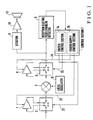
- the radio receiving apparatus includes a high-frequency amplifier 1 for amplifying a reception signal, a first switch 2 for performing a switching operation to disconnect or not to disconnect the high-frequency amplifier 1 from the reception system, a mixer 3 for mixing a high-frequency signal output from said first switch 2 with a local frequency signal to convert the reception signal into a signal in an intermediate-frequency band, an intermediate-frequency amplifier 4 for amplifying the intermediate-frequency signal output from the mixer 3, a second switch 5 for performing a switching operation to disconnect or not to disconnect the intermediate-frequency amplifier 4 from the reception system, a reception electric field strength detector 6 for receiving the intermediate-frequency signal output from the second switch 5 and detecting the electric field strength (level) of the reception signal, a control section 7 for controlling the high-frequency amplifier 1, the intermediate-frequency amplifier 4, and the first and second switches 2 and 5, a local oscillator 8 for oscillating a local frequency signal and outputting it to the mixer 3, a detector 9
- the first and second switches 2 and 5 normally connect the amplifiers 1 and 4 in series with a signal line. When the amplifiers 1 and 4 are disconnected, the input and output terminals of each switch are short-circuited to allow a signal to pass therethrough.
- the high-frequency amplifier 1 and the intermediate-frequency amplifier 4 receive power from a battery (not shown).
- the control section 7 includes a switch control section 7a for controlling the switching operations of the first and second switches 2 and 5 on the basis of the reception electric field strength detected by the reception electric field strength detector 6, and a power supply control section 7b for separately controlling the power ON/OFF operations of the high-frequency amplifier 1 and the intermediate-frequency amplifier 4.
- the first and second switches 2 and 5 are normally switched to the amplifiers 1 and 4 sides, respectively.
- a high-frequency reception signal passes through the first switch 2 and is amplified by the high-frequency amplifier 1.
- the amplified output from the high-frequency amplifier 1 is input to the mixer 3 and mixed with the output from the local oscillator 8 so as to be converted into an intermediate-frequency signal.
- the intermediate-frequency output from the mixer 3 passes through the second switch 5 and is amplified by the intermediate-frequency amplifier 4.
- the amplified output from the intermediate-frequency amplifier 4 is detected by the detector 9, and the signal wave is output.
- the detected output from the local oscillator 8 is amplified by the low-frequency amplifier 10 and converted into a speech signal, which is output from the loudspeaker 11.
- the output from the intermediate-frequency amplifier 4 is input to the reception electric field strength detector 6.
- the reception electric field strength detector 6 detects the electric field strength of the reception signal in accordance with the output from the intermediate-frequency amplifier 4, and outputs the detection result to the control section 7.
- the control section 7 controls the second switch 5 by using a first switching control signal 21 to disconnect the intermediate-frequency amplifier 4 from the reception system, and also controls the intermediate-frequency amplifier 4 by using a first power supply control signal 22 to stop supplying power.
- the first predetermined value indicates the electric field strength at which a necessary S/N can be maintained even if the gain of the intermediate-frequency amplifier 4 becomes zero in the reception system.
- the control section 7 controls the first switch 2 by using a second switching control signal 23 to disconnect the high-frequency amplifier 1 from the reception system, and also controls the high-frequency amplifier 1 by using a second power supply control signal 24 to stop supplying power.
- the second predetermined value indicated the electric field strength at which a necessary S/N can be maintained even if the gain of the high-frequency amplifier 1 becomes zero as well as the gain of the intermediate-frequency amplifier 4.
- the intermediate-frequency amplifier and the high-frequency amplifier are used as amplifiers which are to be disconnected from the circuit of the reception system and for which the supply of power is to be stopped.
- the types of amplifiers and the like to be disconnected and the disconnecting order are not limited. If, for example, the current consumption amounts of a plurality of amplifiers are different from each other, the amplifiers to be disconnected from the reception system may be sequentially selected one by one in accordance with the reception electric field strength. In addition, a combination of at least two amplifiers may be disconnected from the reception system in accordance with a combination pattern based on the result of comparison between a plurality of reference electric field levels and a reception electric field level.
- control section 7 stops supplying power by controlling the amplifiers 1 and 4. If, however, an amplifier having no power control function is used, a power switch may be arranged in a power supply path, and the ON/OFF operation of the power switch may be controlled by the control section 7.
- the above description is associated with the radio receiving apparatus. However, the present invention may be applied to a radio transmitting/receiving apparatus, and power control may be performed on circuit elements other than the amplifiers as long as a receiving operation can be performed.
- the above description is associated with the radio receiving apparatus using a battery with a limited current-carrying capacity as a power supply.
- the present invention may be applied to a radio receiving apparatus using a power supply whose current-carrying capacity is not limited. In this case, an energy saving operation can be performed.
- circuits including the high-frequency amplifier and the intermediate-frequency amplifier are selectively disconnected from the reception system in accordance with the strength.
- the current consumption of the receiving apparatus can be further reduced.
Landscapes
- Input Circuits Of Receivers And Coupling Of Receivers And Audio Equipment (AREA)
- Circuits Of Receivers In General (AREA)
- Transceivers (AREA)
- Superheterodyne Receivers (AREA)
- Mobile Radio Communication Systems (AREA)
Claims (6)
- Funkempfangsgerät mit:einem Hochfrequenzverstärker (1), der mit einer Signalleitung eines Empfangssystems für ein Funksignal verbunden ist und von der Signalleitung getrennt werden kann,einem Zwischenfrequenzverstärker (4), der mit der Signalleitung an einer Ausgabeseite des Hochfrequenzverstärkers (1) verbunden ist und von der Signalleitung getrennt werden kann, undElektrofeldpegel-Detektormitteln (6) zum Erfassen eines Empfangspegels des elektrischen Feldes eines Funksignals,Steuermitteln (7) zum Durchführen einer Steuerung zum Trennen zumindest einen, den Hochfrequenzverstärkers (1) oder den Zwischenfrequenzverstärkers (4), von der Signalleitung und auch zur Durchführung einer Steuerung zur Beendigung der Lieferung von Leistung an den getrennten Verstärker in Übereinstimmung mit dem Pegel des elektrischen Feldes, der durch die Elektrofeldpegel-Detektormittel detektiert wurde, wobei zumindest einer, der Hochfrequenzverstärker (1) oder der Zwischenfrequenzverstärker (4), getrennt wird und die Leistungszufuhr beendet wird, wenn der Pegel des elektrischen Feldes, der durch die Elektrofeldpegel-Detektormittel erfasst wurde, einen vorgegebenen Wert übersteigt,ersten Schaltmitteln (2) zum Trennen des Hochfrequenzverstärkers (1) von der Signalleitung, undzweiten Schaltmitteln (5) zum Trennen des Zwischenfrequenzverstärkers (4) von der Signalleitung,wobei die Steuermittel eine Schaltsteuerung der ersten und zweiten Schaltmittel in Übereinstimmung mit dem Erfassungsergebnis durchführen, das von den Elektrofeldpegel-Detektormitteln erfasst wurde, undwobei die ersten und zweiten Schaltmittel den Hochfrequenzverstärker (1) und den Zwischenfrequenzverstärker (4) normal in Reihe mit der Signalleitung schalten und Eingangs- und Ausgangsanschlüsse des Hochfrequenzverstärkers (1) und des Zwischenfrequenzverstärkers (4) von der Signalleitung trennen, um Signalleitungen, die den getrennten Teilen in einem getrennten Zustand entsprechen, kurzzuschließen.
- Funkempfangsgerät nach Anspruch 1, wobei die Steuermittel die Leistungszufuhr beenden und den Zwischenfrequenzverstärker von der Signalleitung trennen, wenn der erfasste Pegel des elektrischen Feldes einen ersten vorgegebenen Wert überschreitet und wobei
die Steuermittel die Leistungszufuhr an den Hochfrequenzverstärker (1) beenden und ihn von der Signalleitung trennen, wenn der erfasste Pegel des elektrischen Feldes einen zweiten vorgegebenen Wert überschreitet, der größer ist als der erste vorgegebene Wert. - Gerät nach Anspruch 1, wobei die Steuermittel aufweisen:Schaltsteuermittel (7a) zum Steuern der ersten und zweiten Schaltmittel zum Trennen des Hochfrequenzverstärkers (1) und des Zwischenfrequenzverstärkers (4) von der Signalleitung Übereinstimmung mit einem Schaltkombinationsmuster basierend auf dem erfassten Pegel des elektrischen Feldes, der durch die Elektrofeldpegel-Detektormittel erfasst wurde, undLeistungssteuermittel (7b) zum Steuern eines Leistungszufuhrsystems für den Hochfrequenzverstärker (1) und den Zwischenfrequenzverstärker (4) zum Beenden der Leistungszufuhr an den Verstärker, der von der Signalleitung getrennt ist.
- Gerät nach Anspruch 1, wobei die Elektrofeldpegel-Detektormittel eine Anzahl von Referenzpegeln des elektrischen Feldes mit dem Pegel des elektrischen Feldes des Empfangssignals vergleichen und die Steuermittel einen Verstärker bestimmen, der von der Signalleitung zu trennen ist, in Übereinstimmung mit dem Vergleichsergebnis derart, dass ein erforderliches S/N-Verhältnis aufrecht erhalten wird.
- Funkempfangsgerät nach Anspruch 1, mit ferner:einem lokalen Oszillator (8) zum Oszillieren eines lokalen Frequenzsignals,einem Mixer (3) zum Mischen der Ausgabe des Hochfrequenzverstärkers (1) mit dem lokalen Frequenzsignal von dem lokalen Oszillator, um ein Zwischenfrequenzsignal auszugeben, wobeider Zwischenfrequenzverstärker (4) in Reihe mit der Signalleitung geschaltet ist, um das Zwischenfrequenzsignal von dem Mixer zu verstärken.
- Gerät nach Anspruch 5, mit einem Detektor (9) zum Erfassen der Ausgabe des Zwischenfrequenzsignals von dem zweiten Schalter und zum Extrahieren einer Signalwelle,
einem Tieffrequenzverstärker (10) zum Verstärken der Ausgabe des Detektors und
einem Sprachwandler (11) zum Wandeln der Ausgabe des Tieffrequenzverstärkers in ein Sprachsignal und zum Ausgeben des Signals.
Applications Claiming Priority (3)
| Application Number | Priority Date | Filing Date | Title |
|---|---|---|---|
| JP7318840A JPH09162773A (ja) | 1995-12-07 | 1995-12-07 | 消費電流低減機能付無線送受信装置 |
| JP31884095 | 1995-12-07 | ||
| JP318840/95 | 1995-12-07 |
Publications (3)
| Publication Number | Publication Date |
|---|---|
| EP0777334A2 EP0777334A2 (de) | 1997-06-04 |
| EP0777334A3 EP0777334A3 (de) | 1999-07-14 |
| EP0777334B1 true EP0777334B1 (de) | 2006-02-01 |
Family
ID=18103549
Family Applications (1)
| Application Number | Title | Priority Date | Filing Date |
|---|---|---|---|
| EP96119122A Expired - Lifetime EP0777334B1 (de) | 1995-12-07 | 1996-11-28 | Funkempfänger mit Funktion zur Reduzierung des Stromverbrauchs |
Country Status (4)
| Country | Link |
|---|---|
| US (1) | US5797090A (de) |
| EP (1) | EP0777334B1 (de) |
| JP (1) | JPH09162773A (de) |
| DE (1) | DE69635773T2 (de) |
Families Citing this family (20)
| Publication number | Priority date | Publication date | Assignee | Title |
|---|---|---|---|---|
| JP2877081B2 (ja) * | 1996-06-26 | 1999-03-31 | 日本電気株式会社 | 移動体通信装置 |
| JP2845825B2 (ja) * | 1996-08-14 | 1999-01-13 | 静岡日本電気株式会社 | 無線選択呼出受信機 |
| JPH10173453A (ja) * | 1996-12-09 | 1998-06-26 | Sony Corp | 高周波可変利得増幅装置および無線通信装置 |
| US5896183A (en) * | 1997-03-25 | 1999-04-20 | Terk Technologies Corporation | TV or radio broadcast transmission line amplifier with switch bypass controlled at the receiver side |
| JPH10303772A (ja) * | 1997-04-25 | 1998-11-13 | Alps Electric Co Ltd | セルラ−電話機の受信回路 |
| DE19742346C2 (de) * | 1997-09-25 | 2002-12-05 | Siemens Ag | Anordnung und Verfahren zur Vorverstärkung von Empfangssignalen für eine Funkstation |
| KR100241780B1 (ko) | 1997-12-16 | 2000-02-01 | 윤종용 | 무선 통신 단말기의 전원 절약 장치 |
| US6107878A (en) * | 1998-08-06 | 2000-08-22 | Qualcomm Incorporated | Automatic gain control circuit for controlling multiple variable gain amplifier stages while estimating received signal power |
| US6487419B1 (en) * | 1998-08-06 | 2002-11-26 | Ericsson Inc. | Systems and methods for management of current consumption and performance in a receiver down converter of a wireless device |
| JP2002525952A (ja) | 1998-09-21 | 2002-08-13 | コーニンクレッカ フィリップス エレクトロニクス エヌ ヴィ | 増幅器 |
| KR100617739B1 (ko) * | 1999-11-18 | 2006-08-28 | 삼성전자주식회사 | 부호분할 다중접속 단말기의 수신 장치 및 방법 |
| US6725026B2 (en) * | 1999-12-29 | 2004-04-20 | Samsung Electronics Co., Ltd. | Intermodulation control device and method in mobile communication system |
| KR20010076827A (ko) * | 2000-01-28 | 2001-08-16 | 윤종용 | 무선단말기의 증폭기 제어장치 |
| EP1215820A3 (de) | 2000-12-05 | 2004-04-14 | Zarlink Semiconductor Limited | Hochfrequenztuner |
| US7317903B2 (en) * | 2003-09-30 | 2008-01-08 | Sharp Kabushiki Kaisha | Wireless communication circuit, wireless communication apparatus, and wireless communication system |
| KR100739778B1 (ko) * | 2005-12-23 | 2007-07-13 | 삼성전자주식회사 | 전력 소모를 최적화하기 위한 디지털 방송 수신기 및 방법 |
| US8060041B2 (en) * | 2006-02-09 | 2011-11-15 | Qualcomm, Incorporated | Adaptive receiver for wireless communication device |
| US20080111623A1 (en) * | 2006-11-15 | 2008-05-15 | Microtune (Texas), L.P. | Input signal power control |
| JP4945548B2 (ja) * | 2008-02-08 | 2012-06-06 | ルネサスエレクトロニクス株式会社 | 検波回路とそれを含むrf回路およびそれらを内蔵する携帯機器 |
| CN106788684A (zh) * | 2017-01-18 | 2017-05-31 | 成都科脉通信技术有限公司 | 可移动卫星通信基站及其抗干扰方法 |
Citations (1)
| Publication number | Priority date | Publication date | Assignee | Title |
|---|---|---|---|---|
| EP0675605A2 (de) * | 1994-03-30 | 1995-10-04 | Nokia Mobile Phones Ltd. | Funksystem mit zwei Moden |
Family Cites Families (12)
| Publication number | Priority date | Publication date | Assignee | Title |
|---|---|---|---|---|
| JPS59140727A (ja) * | 1983-01-31 | 1984-08-13 | Fujitsu Ltd | 周波数変換方式 |
| JPS604334A (ja) * | 1983-06-23 | 1985-01-10 | Fujitsu Ltd | 周波数変換形無線受信機 |
| US4823398A (en) * | 1985-12-23 | 1989-04-18 | Kazuya Hashimoto | Diversity receiver |
| JPS62281529A (ja) * | 1986-05-30 | 1987-12-07 | Hitachi Ltd | 移動無線受信方式 |
| JPH0616601B2 (ja) * | 1988-09-07 | 1994-03-02 | 三洋電機株式会社 | 受信電波処理回路のパワーセイブ回路及びそのパワーセイブ方法 |
| US5001776A (en) * | 1988-10-27 | 1991-03-19 | Motorola Inc. | Communication system with adaptive transceivers to control intermodulation distortion |
| GB9005779D0 (en) * | 1990-03-14 | 1990-05-09 | Gen Electric Co Plc | Radio receiver antenna arrangements |
| EP0462782B1 (de) * | 1990-06-16 | 1995-03-01 | Nec Corporation | Empfänger für ein zelluloses Mobilfunkübertragungssystem |
| GB2250402B (en) * | 1990-09-28 | 1995-06-21 | Matsushita Electric Industrial Co Ltd | Power saving apparatus of a radiotelephone |
| JPH0670336B2 (ja) * | 1990-10-15 | 1994-09-07 | ナショナル住宅産業株式会社 | 外壁パネルの取付構造 |
| JPH04354210A (ja) * | 1991-05-31 | 1992-12-08 | Fujitsu Ltd | 通信装置の受信回路 |
| JP3016919B2 (ja) * | 1991-08-28 | 2000-03-06 | 日本電気株式会社 | ダイバーシチ受信装置 |
-
1995
- 1995-12-07 JP JP7318840A patent/JPH09162773A/ja active Pending
-
1996
- 1996-11-27 US US08/757,941 patent/US5797090A/en not_active Expired - Lifetime
- 1996-11-28 DE DE69635773T patent/DE69635773T2/de not_active Expired - Lifetime
- 1996-11-28 EP EP96119122A patent/EP0777334B1/de not_active Expired - Lifetime
Patent Citations (1)
| Publication number | Priority date | Publication date | Assignee | Title |
|---|---|---|---|---|
| EP0675605A2 (de) * | 1994-03-30 | 1995-10-04 | Nokia Mobile Phones Ltd. | Funksystem mit zwei Moden |
Also Published As
| Publication number | Publication date |
|---|---|
| US5797090A (en) | 1998-08-18 |
| EP0777334A3 (de) | 1999-07-14 |
| DE69635773T2 (de) | 2006-08-31 |
| DE69635773D1 (de) | 2006-04-13 |
| JPH09162773A (ja) | 1997-06-20 |
| EP0777334A2 (de) | 1997-06-04 |
Similar Documents
| Publication | Publication Date | Title |
|---|---|---|
| EP0777334B1 (de) | Funkempfänger mit Funktion zur Reduzierung des Stromverbrauchs | |
| US6052572A (en) | Mobile communication apparatus | |
| US6741127B2 (en) | High-frequency amplifier circuit and radio communication apparatus using same | |
| KR0158785B1 (ko) | 무선통신장치 | |
| US20040183593A1 (en) | Power amplification apparatus of portable terminal | |
| US20020142790A1 (en) | Dynamic bias for a power amplifier | |
| GB2363925A (en) | Reduction of mobile phone transmitter amplifier distortion due to output mismatch | |
| KR19980070445A (ko) | 전력 제어 회로 및 이동 전화의 전력 효율을 향상시키는 방법 | |
| US5584056A (en) | Dual-bandwidth cellular telephone switching apparatus | |
| US6236841B1 (en) | Transmission output power control circuit for controlling each of antennas to optimal states | |
| EP1193861B1 (de) | Vorwärtskopplungsverstärker | |
| KR100363358B1 (ko) | 소비전력절감장치 | |
| JP3289197B2 (ja) | 送信電力増幅装置 | |
| JP3813247B2 (ja) | 複数モード共用送信回路 | |
| JP3513138B2 (ja) | 通信端末およびその制御回路 | |
| JPH06252794A (ja) | デジタル無線電話機 | |
| GB2362523A (en) | A transceiver with the bias of an amplifier in the receiver controlled by a baseband processor | |
| GB2341055A (en) | Transmission power control circuit | |
| JPH06338839A (ja) | デジタルセルラー電話機 | |
| KR20000041315A (ko) | 무선통신장치에서 소모전류를 줄이기 위한 장치 및 방법 | |
| KR20050012483A (ko) | 피드백 루프를 이용하여 캐리어 피드스루를 개선한 aqm방식의 업-컨버전 장치 | |
| JPH0879154A (ja) | パワーコントロール回路 | |
| JPH0730957A (ja) | 受信機 | |
| JP2002171135A (ja) | フィードフォワード増幅器 | |
| JPH09199960A (ja) | 電力増幅器 |
Legal Events
| Date | Code | Title | Description |
|---|---|---|---|
| PUAI | Public reference made under article 153(3) epc to a published international application that has entered the european phase |
Free format text: ORIGINAL CODE: 0009012 |
|
| AK | Designated contracting states |
Kind code of ref document: A2 Designated state(s): DE FR GB IT SE |
|
| PUAL | Search report despatched |
Free format text: ORIGINAL CODE: 0009013 |
|
| AK | Designated contracting states |
Kind code of ref document: A3 Designated state(s): DE FR GB IT SE |
|
| 17P | Request for examination filed |
Effective date: 19990610 |
|
| 17Q | First examination report despatched |
Effective date: 20040211 |
|
| GRAP | Despatch of communication of intention to grant a patent |
Free format text: ORIGINAL CODE: EPIDOSNIGR1 |
|
| GRAS | Grant fee paid |
Free format text: ORIGINAL CODE: EPIDOSNIGR3 |
|
| GRAA | (expected) grant |
Free format text: ORIGINAL CODE: 0009210 |
|
| AK | Designated contracting states |
Kind code of ref document: B1 Designated state(s): DE FR GB IT SE |
|
| PG25 | Lapsed in a contracting state [announced via postgrant information from national office to epo] |
Ref country code: IT Free format text: LAPSE BECAUSE OF FAILURE TO SUBMIT A TRANSLATION OF THE DESCRIPTION OR TO PAY THE FEE WITHIN THE PRE;WARNING: LAPSES OF ITALIAN PATENTS WITH EFFECTIVE DATE BEFORE 2007 MAY HAVE OCCURRED AT ANY TIME BEFORE 2007. THE CORRECT EFFECTIVE DATE MAY BE DIFFERENT FROM THE ONE RECORDED.SCRIBED TIME-LIMIT Effective date: 20060201 |
|
| REG | Reference to a national code |
Ref country code: GB Ref legal event code: FG4D |
|
| REF | Corresponds to: |
Ref document number: 69635773 Country of ref document: DE Date of ref document: 20060413 Kind code of ref document: P |
|
| PG25 | Lapsed in a contracting state [announced via postgrant information from national office to epo] |
Ref country code: SE Free format text: LAPSE BECAUSE OF FAILURE TO SUBMIT A TRANSLATION OF THE DESCRIPTION OR TO PAY THE FEE WITHIN THE PRESCRIBED TIME-LIMIT Effective date: 20060501 |
|
| ET | Fr: translation filed | ||
| PLBE | No opposition filed within time limit |
Free format text: ORIGINAL CODE: 0009261 |
|
| STAA | Information on the status of an ep patent application or granted ep patent |
Free format text: STATUS: NO OPPOSITION FILED WITHIN TIME LIMIT |
|
| 26N | No opposition filed |
Effective date: 20061103 |
|
| REG | Reference to a national code |
Ref country code: GB Ref legal event code: 732E Free format text: REGISTERED BETWEEN 20141023 AND 20141029 |
|
| REG | Reference to a national code |
Ref country code: FR Ref legal event code: TP Owner name: LENOVO INNOVATIONS LIMITED (HONG KONG), HK Effective date: 20141119 |
|
| PGFP | Annual fee paid to national office [announced via postgrant information from national office to epo] |
Ref country code: FR Payment date: 20141110 Year of fee payment: 19 |
|
| PGFP | Annual fee paid to national office [announced via postgrant information from national office to epo] |
Ref country code: IT Payment date: 20141110 Year of fee payment: 19 |
|
| PGFP | Annual fee paid to national office [announced via postgrant information from national office to epo] |
Ref country code: DE Payment date: 20151125 Year of fee payment: 20 Ref country code: GB Payment date: 20151125 Year of fee payment: 20 |
|
| PG25 | Lapsed in a contracting state [announced via postgrant information from national office to epo] |
Ref country code: IT Free format text: LAPSE BECAUSE OF NON-PAYMENT OF DUE FEES Effective date: 20151128 |
|
| REG | Reference to a national code |
Ref country code: FR Ref legal event code: ST Effective date: 20160729 |
|
| REG | Reference to a national code |
Ref country code: DE Ref legal event code: R071 Ref document number: 69635773 Country of ref document: DE |
|
| PG25 | Lapsed in a contracting state [announced via postgrant information from national office to epo] |
Ref country code: FR Free format text: LAPSE BECAUSE OF NON-PAYMENT OF DUE FEES Effective date: 20151130 |
|
| REG | Reference to a national code |
Ref country code: GB Ref legal event code: PE20 Expiry date: 20161127 |
|
| PG25 | Lapsed in a contracting state [announced via postgrant information from national office to epo] |
Ref country code: GB Free format text: LAPSE BECAUSE OF EXPIRATION OF PROTECTION Effective date: 20161127 |