EP0778092A1 - Systeme de presse a poin onner et procede de commande approprie - Google Patents
Systeme de presse a poin onner et procede de commande approprie Download PDFInfo
- Publication number
- EP0778092A1 EP0778092A1 EP96918904A EP96918904A EP0778092A1 EP 0778092 A1 EP0778092 A1 EP 0778092A1 EP 96918904 A EP96918904 A EP 96918904A EP 96918904 A EP96918904 A EP 96918904A EP 0778092 A1 EP0778092 A1 EP 0778092A1
- Authority
- EP
- European Patent Office
- Prior art keywords
- press
- time
- servo motor
- control means
- press operation
- Prior art date
- Legal status (The legal status is an assumption and is not a legal conclusion. Google has not performed a legal analysis and makes no representation as to the accuracy of the status listed.)
- Granted
Links
Images


Classifications
-
- B—PERFORMING OPERATIONS; TRANSPORTING
- B21—MECHANICAL METAL-WORKING WITHOUT ESSENTIALLY REMOVING MATERIAL; PUNCHING METAL
- B21D—WORKING OR PROCESSING OF SHEET METAL OR METAL TUBES, RODS OR PROFILES WITHOUT ESSENTIALLY REMOVING MATERIAL; PUNCHING METAL
- B21D28/00—Shaping by press-cutting; Perforating
- B21D28/002—Drive of the tools
-
- B—PERFORMING OPERATIONS; TRANSPORTING
- B21—MECHANICAL METAL-WORKING WITHOUT ESSENTIALLY REMOVING MATERIAL; PUNCHING METAL
- B21D—WORKING OR PROCESSING OF SHEET METAL OR METAL TUBES, RODS OR PROFILES WITHOUT ESSENTIALLY REMOVING MATERIAL; PUNCHING METAL
- B21D28/00—Shaping by press-cutting; Perforating
- B21D28/24—Perforating, i.e. punching holes
- B21D28/26—Perforating, i.e. punching holes in sheets or flat parts
- B21D28/265—Perforating, i.e. punching holes in sheets or flat parts with relative movement of sheet and tools enabling the punching of holes in predetermined locations of the sheet, e.g. holes punching with template
-
- G—PHYSICS
- G05—CONTROLLING; REGULATING
- G05B—CONTROL OR REGULATING SYSTEMS IN GENERAL; FUNCTIONAL ELEMENTS OF SUCH SYSTEMS; MONITORING OR TESTING ARRANGEMENTS FOR SUCH SYSTEMS OR ELEMENTS
- G05B19/00—Program-control systems
- G05B19/02—Program-control systems electric
- G05B19/18—Numerical control [NC], i.e. automatically operating machines, in particular machine tools, e.g. in a manufacturing environment, so as to execute positioning, movement or co-ordinated operations by means of program data in numerical form
- G05B19/4155—Numerical control [NC], i.e. automatically operating machines, in particular machine tools, e.g. in a manufacturing environment, so as to execute positioning, movement or co-ordinated operations by means of program data in numerical form characterised by program execution, i.e. part program or machine function execution, e.g. selection of a program
-
- G—PHYSICS
- G05—CONTROLLING; REGULATING
- G05B—CONTROL OR REGULATING SYSTEMS IN GENERAL; FUNCTIONAL ELEMENTS OF SUCH SYSTEMS; MONITORING OR TESTING ARRANGEMENTS FOR SUCH SYSTEMS OR ELEMENTS
- G05B2219/00—Program-control systems
- G05B2219/30—Nc systems
- G05B2219/34—Director, elements to supervisory
- G05B2219/34391—Synchronize axis movement and tool action, delay action, simulation inertia
-
- G—PHYSICS
- G05—CONTROLLING; REGULATING
- G05B—CONTROL OR REGULATING SYSTEMS IN GENERAL; FUNCTIONAL ELEMENTS OF SUCH SYSTEMS; MONITORING OR TESTING ARRANGEMENTS FOR SUCH SYSTEMS OR ELEMENTS
- G05B2219/00—Program-control systems
- G05B2219/30—Nc systems
- G05B2219/45—Nc applications
- G05B2219/45137—Punch, stamp, also with use die, mould
-
- Y—GENERAL TAGGING OF NEW TECHNOLOGICAL DEVELOPMENTS; GENERAL TAGGING OF CROSS-SECTIONAL TECHNOLOGIES SPANNING OVER SEVERAL SECTIONS OF THE IPC; TECHNICAL SUBJECTS COVERED BY FORMER USPC CROSS-REFERENCE ART COLLECTIONS [XRACs] AND DIGESTS
- Y10—TECHNICAL SUBJECTS COVERED BY FORMER USPC
- Y10T—TECHNICAL SUBJECTS COVERED BY FORMER US CLASSIFICATION
- Y10T83/00—Cutting
- Y10T83/04—Processes
- Y10T83/0524—Plural cutting steps
-
- Y—GENERAL TAGGING OF NEW TECHNOLOGICAL DEVELOPMENTS; GENERAL TAGGING OF CROSS-SECTIONAL TECHNOLOGIES SPANNING OVER SEVERAL SECTIONS OF THE IPC; TECHNICAL SUBJECTS COVERED BY FORMER USPC CROSS-REFERENCE ART COLLECTIONS [XRACs] AND DIGESTS
- Y10—TECHNICAL SUBJECTS COVERED BY FORMER USPC
- Y10T—TECHNICAL SUBJECTS COVERED BY FORMER US CLASSIFICATION
- Y10T83/00—Cutting
- Y10T83/162—With control means responsive to replaceable or selectable information program
-
- Y—GENERAL TAGGING OF NEW TECHNOLOGICAL DEVELOPMENTS; GENERAL TAGGING OF CROSS-SECTIONAL TECHNOLOGIES SPANNING OVER SEVERAL SECTIONS OF THE IPC; TECHNICAL SUBJECTS COVERED BY FORMER USPC CROSS-REFERENCE ART COLLECTIONS [XRACs] AND DIGESTS
- Y10—TECHNICAL SUBJECTS COVERED BY FORMER USPC
- Y10T—TECHNICAL SUBJECTS COVERED BY FORMER US CLASSIFICATION
- Y10T83/00—Cutting
- Y10T83/647—With means to convey work relative to tool station
- Y10T83/654—With work-constraining means on work conveyor [i.e., "work-carrier"]
- Y10T83/6563—With means to orient or position work carrier relative to tool station
- Y10T83/6566—By indexing means
-
- Y—GENERAL TAGGING OF NEW TECHNOLOGICAL DEVELOPMENTS; GENERAL TAGGING OF CROSS-SECTIONAL TECHNOLOGIES SPANNING OVER SEVERAL SECTIONS OF THE IPC; TECHNICAL SUBJECTS COVERED BY FORMER USPC CROSS-REFERENCE ART COLLECTIONS [XRACs] AND DIGESTS
- Y10—TECHNICAL SUBJECTS COVERED BY FORMER USPC
- Y10T—TECHNICAL SUBJECTS COVERED BY FORMER US CLASSIFICATION
- Y10T83/00—Cutting
- Y10T83/929—Tool or tool with support
- Y10T83/9411—Cutting couple type
- Y10T83/9423—Punching tool
Definitions
- This invention relates to a punch press system comprising a type of punch press whose press operation is enabled by a servo motor, and a CNC unit (a computerized numerical control unit) for controlling the servo motor, and further, to a method of controlling such a punch press system.
- a table on which a workpiece is fixed is positioned. After positioning of the table is completed, a pressing command signal is sent to the punch press.
- the punch press receives this pressing command signal, the punch press rotates a flywheel to operate a ram of the punch press, and executes press work by a press tool attached to the ram.
- the speed-up of press work by the punch press is needed.
- a conventional punch press performs press operation in accordance with the rotation of the flywheel, the command for operation through a programmable controller is required.
- the working speed of the flywheel itself is delayed, the response of press operation to a command is degraded.
- the working speed of the flywheel is substantially fixed, only simple operation is allowed.
- a punch press using a servo motor to control press operation is provided.
- a controller dedicated to press operation is required to be provided separately from a CNC unit, so that the cost is increased.
- a command to the servo motor is sent from the CNC unit through a controller for the servo motor, the speed-up of processing rate is limited.
- a punch press system comprises a punch press and a CNC unit.
- the punch press includes a ram having an end to which a tool for pressing and punching a workpiece is attached, a servo motor for press to control the linear movement of the ram, a table on which the workpiece is to be fixed, and a servo motor for table for positioning the table, while the CNC unit includes a position control means for controlling the position of the table by operating the servo motor for table according to a working program, a press operation data storage means for storing an operation command to be issued to the servo motor for press, and a press operation control means for reading out the operation command stored in the press operation data storage means and controlling the servo motor for press according to the read-out operation command.
- the position control means is provided with a function for issuing a read-out start signal to the press operation control means at the time earlier by a predetermined time than the time, at which position control is completed in one working cycle, whereby, when the press operation control means receives the read-out start signal from the position control means, the press operation control means starts to read out the operation command for controlling the servo motor for press from the press operation data storage means.
- the CNC unit in the punch press system controls the servo motor for table to drive the table on which a workpiece is fixed, and also controls the servo motor for press to drive the press tool of the punch press.
- a method of controlling the punch press system according to the present invention comprises the following steps: starting the position control of a table by driving a servo motor for table; starting the driving of a servo motor for press at the time which went back to the past from the time when position control for the table is completed, by the time which is close to but not execeeding approach time required for the press tool to approache to a workpiece from its home position; lowering the press tool halfway at a rapid acceleration according to an operation pattern stored in a CNC unit during approach stroke to the workpiece, which is the process for starting operation; lowering the press tool to an approach end position while gradually reducing its lowering speed; lowering the press tool at a low substantially fixed speed during press operation following the approach; lowering the press tool at rapid acceleration again during punching operation after press operation is finished; lifting the
- press operation data created in advance is read out according to the position control of the table, and the servo motor for press is controlled according to the read-out press operation data to control the operation of the press tool, so that it is possible to configure a punch press system which has a simple structure and is excellent responsibility.
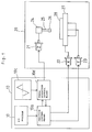
- a punch press system comprises a CNC unit 10 and a punch press 20, in which its operation is controlled by the CNC unit 10.
- the punch press 20 includes an XY table 27 for loading and fixing a workpiece 28, an X-axis servo motor 22 for moving the XY table 27 in the direction of X-axis, a Y-axis servo motor 23 for moving the XY table 27 in the direction of Y-axis, a ram 25 having the end to which a tool 26 is attached, and a Z-axis servo motor 21 for moving the ram 25 through a power transmission section 24 in the direction (in the direction of Z-axis) perpendicular to the surface (the XY plane) on which table 27 moves.
- the CNC unit 10 includes a position control means 10a, which moves and controls the position of the XY table 27 on the XY plane by issuing a command to the X-axis servo motor 22 and the Y-axis servo motor 23 according to a working program (an NC program) 10b.
- a position control means 10a which moves and controls the position of the XY table 27 on the XY plane by issuing a command to the X-axis servo motor 22 and the Y-axis servo motor 23 according to a working program (an NC program) 10b.
- the CNC unit 10 includes a press operation data storage means 10c capable of storing the data to determine a pattern in one cycle of press operation by the punch press 20, and a press operation control means 10d capable of reading out press operation data, which is previously stored in the press operation data storage means 10c from the press operation data storage means 10c in response to the output from the position control means 10a, and capable of controlling the Z-axis servo motor 21 according to the read-out operation data.
- a press operation data storage means 10c capable of storing the data to determine a pattern in one cycle of press operation by the punch press 20
- a press operation control means 10d capable of reading out press operation data, which is previously stored in the press operation data storage means 10c from the press operation data storage means 10c in response to the output from the position control means 10a, and capable of controlling the Z-axis servo motor 21 according to the read-out operation data.
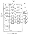
- a processor 11 is connected, through a bus 19, to each of ROM 12 for storing a system program, RAM 13 for temporarily storing computational data and display data or the like, CMOS 14 for storing the correction quantity of tool, the error correction quantity of pitch, a working program and parameters or the like, an interface 15 for external device, a programmable machine controller (PMC) 36 for controlling the punch press, a graphic control circuit 16, an interface 17 for connecting a key board 33, an interface 18 for connecting a manual pulse generator 35 and axis control circuits 41 to 43 for receiving a command for moving each axis and outputting the received command to servo amplifiers 51 to 53.
- PMC programmable machine controller
- the processor 11 reads out the system program stored in ROM 12 through the bus 19, and controls the whole CNC unit 10 according to the read-out system program.
- SRAM or the like is used for RAM 13.
- CMOS 14 constitutes the press operation data storage means 10c shown in Fig. 1. Since this CMOS 14 is backed up by a battery (not shown), data stored in CMOS is held as it is even if the power supply to CNC unit 10 is interrupted.
- a paper tape reader, a paper tape puncher and an external device 34 such as a printer are connected to the interface 15 for the external device.
- a working program is read from the paper tape reader to the interface 15, and the interface 15 is able to output a working program edited in the CNC unit 10 to the paper tape puncher.
- the graphic control circuit 16 converts digital data such as the current position of each axis, an alarm, a parameter and image data into an image signal and outputs the image signal.
- This image signal is sent to a display 32 of a manual input unit with a display (CRT/MDI unit) 31 and is displayed on the display.
- the interface 17 receives data through the keyboard 33 in CRT/MDI unit 31 and sends the received data to the processor 11.
- the interface 18 is connected to the manual pulse generator 35 and receives a pulse from the manual pulse generator 35.
- the manual pulse generator 35 is mounted on a mechine control panel and is used for manually moving the punch press 20 with accuracy.
- the programmable machine controller (PMC) 36 is built in the CNC unit 10 and controls the punch press according to a sequence program created in the form of a random-access discrete address (RADA). That is, the programmable machine controller converts M function, S function and T function commanded by a working program into a signal required for the punch press according to a sequence program, and outputs the signal to the punch press through an I/O unit 37. This output signal drives a magnet or the like in the punch press and operates a hydraulic valve, a pneumatic valve, an electric actuator or the like.
- the programmable machine controller receives a signal from a limit switch for the punch press and from a switch or the like on the mechanical control panel, performs the processing required for the signal and sends the processed signal to the processor 11.
- the axis control circuits 41 to 43 receive a command for moving each axis (X-axis, Y-axis and Z-axis) from the processor 11 and outputs the received command for each axis to the servo amplifiers 51 to 53.
- Each of the servo amplifiers 51 to 53 receives this command and drives the corresponding servo motor 21 to 23 for each axis.
- a pulse coder (not shown) for detecting a position is built in each of the servo motors 21 to 23, and the position signal is fed back from this pulse coder as a pulse train.
- a speed signal can be generted by F/V (frequency/velocity) conversion of this pulse train. However, in Fig. 2, the feedback line of this position signal and the feedback of a speed are omitted.
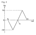
- Fig. 3 is a graph showing an embodiment of an operational pattern of press operation in one cycle between approach of the press tool 26 from its home position to the workpiece 28 and return to the home position through pressing and punching.
- a horizontal axis represents time
- a vertical axis represents speed Vp at which the press tool 26 is moved in the direction of Z-axis (the amount of movement during every predetermined period).
- the press tool 26 is rapidly accelerated from the time t0, at which press operation is started (the time at which approach is started), up to the maximum lowering speed (-Vd).
- the press tool 26 is decelerated until the press tool reaches an approach end position, and continues decelerated lowering movement at the following stage of the pressing workpiece and the subsequent stage of punching workpiece.
- time t1 the movement of the press tool 26 is changed from the lowering movement to lifting movement (return movement).
- the press tool 26 is rapidly accelerated again up to the maximum lifting speed (Vu).
- Vu maximum lifting speed
- the press tool 26 is decelerated while returning to the home position and is stopped (time t2).
- CMOS 14 Data for determining such operational pattern of the punch press is stored in CMOS 14 in the form of the amount of movement during each predetermined period (each interpolation period or each period including two or more interpolation periods). That is, the press operation data storage means 10c shown in Fig. 1 is constituted by CMOS 14 in the CNC unit 10 shown in Fig. 2. This data is read out every predetermined period (interpolation period), and is sent to the servo amplifier 51 through the axis control circuit 41 for press to rotate the servo motor 21 for Z-axis through the angle corresponding to the movement during the predetermined period (interpolation period). As a result, the press tool 26 is operated according to a preset operational pattern.
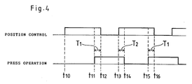
- press operation is started at the time T11 earlier, by predetermined time T1, than the time T12 at which positioning is completed.
- This predetermined time T1 is set on the basis of the operating characteristics or the like of the operational pattern shown in Fig. 3 so that the predetermined time T1 is within the approach time of the press tool 26 and as close to the approach time as possible.
- the time T1 may peviouly be stored in a memory as a parameter or may be calculad as required.
- predetermined time T2 is set on the basis of the operating characteristics or the like of the operational pattern shown in Fig. 3 so that the predetermined time is a time starting from a time when the press tool 26 is separated from the workpiece 28 and ending when the press tool is returned to its home position, that is, the predetermined time is in the range not exceeding return time and as close to the return time as possible.
- predetermined times T1 and T2 they may be either previously stored in a memory as a parameter or calculated as required.
- Fig. 5 is a flow chart showing a processing procedure by the processor 11 for executing such press operation.
- the processor 11 reads out the working program from CMOS 14 constituting the press operation data storage means 10c, and starts positioning control according to its first block (Step S1).
- positioning control the number of interpolation periods and the quantity of movement distributed for each interpolation period are calculated according to a movement command written in the present (first) read-out block (concering the X- and Y-coordinate values of a movement start point and a movement end point and a moving speed).
- the number P1 of interpolation periods equivalent to the time from positioning control start time t10 till press operation start time t11, is obtained by converting the time from the start of positioning control (time t10) till the end of positioning control (time t12) into the number of interpolation periods and then subtracting the number of interpolation periods equivalent to the time T1 from the number thus converted.
- Step S2 the number of interpolation periods, successively executed, is counted up (Step S2). Processing in this step is repeated until the count value reaches P1, that is, the number equivalent to the time from the positioning control start time t10 to the press operation start time t11.
- P1 that is, the current time reaches t11
- data for determining the operational pattern of the punch press is read out from CMOS 14 as the press operation data storage means 10c for each predetermined period (interpolation period), and the punch press is operated according to the read-out data (Step S3).
- the number Q1 of predetermined periods (interpolation periods) equivalent to the time from the press operation start time t11 till positioning control start time t13 written in the next block is obtained by obtaining the time from the start of press operation (time t11) till the end of the press operation (time t14) on the basis of the number of predetermined periods (interpolation periods) and then subtracting from the foregoing number the number of predetermined periods (interpolation periods) equivalent to the time T2 from the number thus obtained.
- Step S4 the number of predetermined periods (interpolation periods) in which data is successively read out from CMOS 14 is counted up (Step S4). Processing in this step is repeated until the count value reaches Q1, that is, the number equivalent to the time from the press operation start time t11 to the following positioning start time t13.
- Q1 that is, when current time has reached t13
- positioning control is started (Step S5).
- Step S6 the processor 11 executes the same positioning processing as that in Step S1, and thereafter, returns to Step S2 to start press operation.
- the time from the start of positioning control till the end thereof (the time from the time t10 till the time t12) and the time from the start of press operation till the end thereof (the time from the time t11 till the time t14) are obtained by counting the number of periods.
- the time R1 (the time from the time t10 till the time t12), at which positioning control is executed, is calculated on the bases of a moving speed and the amount of movement in the movement command, and the time, at which the time R1-T1 is measured by the timer that is started at the positioning control start time (the time t10), may be set as the press operation start time (the time t11).
- time S1 (the time from the time t11 till the time t14), at which press operation is executed, is obtained from the data stored in CMOS 14 for determining the operational pattern of the punch press, and the time, at which time S1-T2 is meared by the timer that is started at the press operation start time (the time t11), may be set as the positioning control start time (the time t13).
- the press tool 26 is operated by the servo motor controlled by the CNC unit 10, it is possible to configure a punch press system which has a simple structure and is excellent in responsibility. As a result, press operation is able to be executed at a high speed even at a low cost.
- press operation is started at the time t11 earlier, by the predetermined time T1, than the time t12 at which positioning is completed, and the next positioning operation is started at the time t13 earlier, by the predetermined time T2 than the time t14 at which press operation is finished. Therefore, waiting time between the completion of positioning control and the start of press operation and waiting time between the start of press operation and the start of positioning control in a working cycle are reduced to a largest possible extent. As a result, high speed press operation is made possible.
- the pattern of press operation is stored in the form of the data of movement amount for each predetermined period corresponding to one interpolation period or two or more interpolation periods, and the data is read out for each predetermined period and is outputted to the servo motor.
- One embodiment of the pattern of press operation is shown in Fig. 3; however, a plurality of other patterns may be prepared and may be selected according to a command or the like by an operator.
- the time from the start of press operation till the start of the next positioning control (the time from the time t11 till the time t13) or the number of predetermined periods (interpolation periods) correspoding to such a time may also be stored along with the data for determining the pattern.
- a caluculation for obtaining the time of press operation or the number of interpolation periods, prior to the start of press operation would not require much time.
- a command for starting positioning control may also be stored, when the pattern of press operation is set, in an address in which a movement command (a command for movement amount in a predetermined period) corresponding to the time t13, at which the next positioning control is started, is stored.
- Fig. 6 is a graph showing an operational pattern different form the operational pattern of press operation shown in Fig. 3, though the vertical and horizontal axes are the same as those in Fig. 3.
- the press tool 26 is accelerated from approach start time (time t20) up to the maximum lowering speed (-Vd) and is then decelerated to complete its approach stroke (time t21).
- the press tool 26 presses the workpiece 28, while maintaining the lowering speed (-Vm) of the time when approach was completed.
- time t22 work for punching the workpiece 28 is started (time t22)
- the lowering speed is accelerated again, and the press tool punches the workpiece with the lowering speed accelerated and punching is completed (time t23).
- the press tool 26 which has finished punching is rapidly accelerated in the return direction (in the lifting direction) up to the maximum lifting speed (Vu). Then, the press tool is decelerated, while returning to the home position and is stopped (time t24). As described above, the press tool 26 is operated at a low fixed lowering speed (-Vm) between the end of approach (the time t21) and the start of the operation for punching the workpiece (the time t22), so that the shock at the time of the contact between the workpiece 28 and the press tool 26, as well as the noise, can be reduced. On the other hand, approach, punching and retreat are performed at a high speed, so that working time can be reduced.
- the press operation data created in advance is read out according to the positioning control of the table, and the operation of the press tool is controlled by controlling the servo motor for press according to the read-out press operation data, so that it is possible to configure a punch press system which has a simple structure and is excellent in responsibility. Therefore, press operation can be executed at a high speed, as well as at a low cost.
Landscapes
- Engineering & Computer Science (AREA)
- Mechanical Engineering (AREA)
- Human Computer Interaction (AREA)
- Manufacturing & Machinery (AREA)
- Physics & Mathematics (AREA)
- General Physics & Mathematics (AREA)
- Automation & Control Theory (AREA)
- Control Of Presses (AREA)
- Numerical Control (AREA)
- Punching Or Piercing (AREA)
Applications Claiming Priority (4)
| Application Number | Priority Date | Filing Date | Title |
|---|---|---|---|
| JP160239/95 | 1995-06-27 | ||
| JP16023995 | 1995-06-27 | ||
| JP7160239A JPH0910858A (ja) | 1995-06-27 | 1995-06-27 | パンチプレス機システムおよび制御方法 |
| PCT/JP1996/001756 WO1997001405A1 (fr) | 1995-06-27 | 1996-06-25 | Systeme de presse a poinçonner et procede de commande approprie |
Publications (3)
| Publication Number | Publication Date |
|---|---|
| EP0778092A1 true EP0778092A1 (fr) | 1997-06-11 |
| EP0778092A4 EP0778092A4 (fr) | 1999-08-25 |
| EP0778092B1 EP0778092B1 (fr) | 2003-05-14 |
Family
ID=15710718
Family Applications (1)
| Application Number | Title | Priority Date | Filing Date |
|---|---|---|---|
| EP96918904A Expired - Lifetime EP0778092B1 (fr) | 1995-06-27 | 1996-06-25 | Systeme de presse a poinconner et procede de commande approprie |
Country Status (5)
| Country | Link |
|---|---|
| US (1) | US5931070A (fr) |
| EP (1) | EP0778092B1 (fr) |
| JP (1) | JPH0910858A (fr) |
| DE (1) | DE69628125T2 (fr) |
| WO (1) | WO1997001405A1 (fr) |
Cited By (2)
| Publication number | Priority date | Publication date | Assignee | Title |
|---|---|---|---|---|
| EP1281452A3 (fr) * | 1998-10-19 | 2004-09-01 | Mika Virtanen | Centre de fabrication de toles et procédés utilisés dans ce centre pour la fabrication optimale de toles à travailler |
| EP2067544A1 (fr) * | 2007-12-06 | 2009-06-10 | Trumpf Werkzeugmaschinen GmbH + Co. KG | Procédé et machine-outil destinés au traitement de pièces à usiner |
Families Citing this family (16)
| Publication number | Priority date | Publication date | Assignee | Title |
|---|---|---|---|---|
| US6418824B1 (en) * | 2000-03-03 | 2002-07-16 | Pcps Limited Partnership | Two stage punch press actuator with output drive shaft position sensing |
| JP4080249B2 (ja) * | 2002-06-04 | 2008-04-23 | 日立ビアメカニクス株式会社 | 加工方法 |
| US7325437B2 (en) * | 2004-04-13 | 2008-02-05 | Jeff Boatright | Long reach press |
| DE102007008698A1 (de) * | 2007-02-20 | 2008-08-21 | Deutsche Mechatronics Gmbh | Verfahren zur optischen Voreinrichtung von Stanzmaschinenwerkzeugen und Vorrichtung zur Durchführung |
| US7723178B2 (en) * | 2008-07-18 | 2010-05-25 | International Business Machines Corporation | Shallow and deep trench isolation structures in semiconductor integrated circuits |
| CN101887250B (zh) * | 2009-05-12 | 2012-05-30 | 鸿富锦精密工业(深圳)有限公司 | Cnc工具机控制装置 |
| JP5476100B2 (ja) * | 2009-11-18 | 2014-04-23 | ファナック株式会社 | パンチプレス機を制御する数値制御装置 |
| CN102161063B (zh) * | 2011-01-04 | 2013-06-26 | 安徽工业大学 | 一种用于金属带材的连续冲孔装置 |
| WO2012146286A1 (fr) * | 2011-04-28 | 2012-11-01 | Voith Patent Gmbh | Machine à estamper et/ou à grignoter et procédé de commande d'une machine à estamper et/ou à grignoter |
| US9459198B2 (en) * | 2014-03-17 | 2016-10-04 | Shenzhen China Star Optoelectronics Technology Co., Ltd. | Pressing and tearing apparatus and method for peeling rate tests |
| US10712728B2 (en) * | 2015-11-20 | 2020-07-14 | Kabushiki Kaisha Yaskawa Denki | Motor control apparatus and method of controlling motor control apparatus |
| JP6412087B2 (ja) | 2016-11-22 | 2018-10-24 | ファナック株式会社 | 数値制御装置 |
| CN107081390A (zh) * | 2017-05-31 | 2017-08-22 | 嘉兴宝程自动化设备有限公司 | 全自动冲床送料机、全自动冲床送料机纠偏方法及系统 |
| CN107088590A (zh) * | 2017-06-07 | 2017-08-25 | 嘉兴宝程自动化设备有限公司 | 一种快速识别板材偏移的冲床送料机及其工作方法 |
| JP6549647B2 (ja) | 2017-07-26 | 2019-07-24 | ファナック株式会社 | 数値制御装置 |
| JP6549648B2 (ja) | 2017-07-26 | 2019-07-24 | ファナック株式会社 | 数値制御装置 |
Family Cites Families (14)
| Publication number | Priority date | Publication date | Assignee | Title |
|---|---|---|---|---|
| US3979985A (en) * | 1973-08-06 | 1976-09-14 | U.S. Amada, Ltd. | Sheet transfer between a turret punch press and an adjacent apparatus |
| US4257000A (en) * | 1979-05-01 | 1981-03-17 | General Electric Company | Apparatus for controlling the length of movement of a controlled member along a path of repeated operating positions |
| JPS59212135A (ja) * | 1983-05-17 | 1984-12-01 | Aida Eng Ltd | プレス装置の制御方法 |
| US4628578A (en) * | 1983-08-19 | 1986-12-16 | Kabushiki Kaisha Komatsu Seisakusho | Method and apparatus for automatic punching |
| DD296451B5 (de) * | 1990-07-10 | 1995-08-24 | Umformtechnik Erfurt Gmh | Verfahren und Anordnung zur Koordinierung von Achsantrieben fuer sich ueberlagernde Bewegungsablaeufe von flexiblen Blechteiltransporteinrichtungen mimit Eigenantrieb an Pressen |
| JP2584889B2 (ja) * | 1990-07-26 | 1997-02-26 | ファナック株式会社 | パンチプレス機械の工具選択方法 |
| JP3083101B2 (ja) * | 1990-08-15 | 2000-09-04 | 上野精機株式会社 | プレス装置 |
| JPH05100733A (ja) * | 1991-10-03 | 1993-04-23 | Fanuc Ltd | パンチプレス機械の加工方法 |
| JPH05169151A (ja) * | 1991-12-16 | 1993-07-09 | Mekatoro Joban Internatl:Kk | パンチプレス機 |
| US5333525A (en) * | 1992-06-05 | 1994-08-02 | General Electric Company | Apparatus and method for producing motor laminations from a blank |
| DE4218818A1 (de) * | 1992-06-06 | 1993-12-09 | Mueller Weingarten Maschf | Transporteinrichtung |
| US5435216A (en) * | 1993-07-28 | 1995-07-25 | Strippit, Inc. | Method and apparatus for operating a hydraulic ram |
| US5588344A (en) * | 1994-06-13 | 1996-12-31 | Murata Machinery, Ltd. | Electric servo motor punch press ram drive |
| JPH08108300A (ja) * | 1994-10-06 | 1996-04-30 | Murata Mach Ltd | パンチプレスの動作制御装置 |
-
1995
- 1995-06-27 JP JP7160239A patent/JPH0910858A/ja active Pending
-
1996
- 1996-06-25 WO PCT/JP1996/001756 patent/WO1997001405A1/fr not_active Ceased
- 1996-06-25 DE DE69628125T patent/DE69628125T2/de not_active Expired - Fee Related
- 1996-06-25 EP EP96918904A patent/EP0778092B1/fr not_active Expired - Lifetime
-
1997
- 1997-02-27 US US08/793,478 patent/US5931070A/en not_active Expired - Fee Related
Cited By (6)
| Publication number | Priority date | Publication date | Assignee | Title |
|---|---|---|---|---|
| EP1281452A3 (fr) * | 1998-10-19 | 2004-09-01 | Mika Virtanen | Centre de fabrication de toles et procédés utilisés dans ce centre pour la fabrication optimale de toles à travailler |
| EP1281453A3 (fr) * | 1998-10-19 | 2004-10-13 | Mika Virtanen | Centre de fabrication de toles et procédés utilisés dans ce centre pour la fabrication optimale de toles à travailler |
| EP2338619A3 (fr) * | 1998-10-19 | 2018-05-02 | Finn-Power OY | Centre de fabrication de tôles et procédés utilisés dans ce centre pour la fabrication optimale de tôles à travailler |
| EP2067544A1 (fr) * | 2007-12-06 | 2009-06-10 | Trumpf Werkzeugmaschinen GmbH + Co. KG | Procédé et machine-outil destinés au traitement de pièces à usiner |
| JP2009137009A (ja) * | 2007-12-06 | 2009-06-25 | Trumpf Werkzeugmaschinen Gmbh & Co Kg | 工作物を加工するための方法及び工作機械 |
| US8126586B2 (en) | 2007-12-06 | 2012-02-28 | Trumpf Werkzeugmaschinen Gmbh + Co. Kg | Methods and machine tools for processing workpieces |
Also Published As
| Publication number | Publication date |
|---|---|
| DE69628125D1 (de) | 2003-06-18 |
| EP0778092B1 (fr) | 2003-05-14 |
| EP0778092A4 (fr) | 1999-08-25 |
| DE69628125T2 (de) | 2003-11-27 |
| US5931070A (en) | 1999-08-03 |
| WO1997001405A1 (fr) | 1997-01-16 |
| JPH0910858A (ja) | 1997-01-14 |
Similar Documents
| Publication | Publication Date | Title |
|---|---|---|
| US5931070A (en) | Punch press system and its control method | |
| US6885909B2 (en) | Numerical controller | |
| KR950015163B1 (ko) | 펀치 프레스 기계의 운전 재개 방법 및 수치 제어 장치 | |
| WO1994023869A1 (fr) | Appareil d'usinage a commande numerique | |
| JP2584889B2 (ja) | パンチプレス機械の工具選択方法 | |
| US6909938B2 (en) | Method of and apparatus for synchronous control | |
| JP2006004275A (ja) | 数値制御装置 | |
| JP3795854B2 (ja) | レーザ加工装置 | |
| EP0460220A1 (fr) | Systeme d'affichage pour commande numerique de machine-outil | |
| US5298006A (en) | Machining method of punch press machine | |
| JPH11143514A (ja) | 加工誤差チェックができる数値制御装置 | |
| EP1403747A2 (fr) | Commande numérique | |
| EP1720083A2 (fr) | Contrôleur numérique | |
| JP2571319B2 (ja) | パンチプレス機械の工具交換方法 | |
| KR940010397B1 (ko) | 피치 오차 정정 데이타의 리로딩 방법 | |
| JP2862211B2 (ja) | 数値制御装置の主軸の速度到達検出方法 | |
| JP2762366B2 (ja) | セーフティゾーン設定方式 | |
| JPH05309546A (ja) | 数値制御工作機械の加工時間計算方法及びその装置 | |
| JPH07334223A (ja) | 工具軸姿勢制御方式 | |
| CN109308050B (zh) | 数值控制装置 | |
| JPH03161808A (ja) | 工具形状の入力描画方式 | |
| JPH06304845A (ja) | 数値制御装置 | |
| JPH07155860A (ja) | パンチプレスの動作制御方式 | |
| JPH0651822A (ja) | 対話形数値制御装置のアニメ描画方法 | |
| JPH0325511A (ja) | 数値制御装置の教示データ作成方式及び加工速度制御方式 |
Legal Events
| Date | Code | Title | Description |
|---|---|---|---|
| PUAI | Public reference made under article 153(3) epc to a published international application that has entered the european phase |
Free format text: ORIGINAL CODE: 0009012 |
|
| 17P | Request for examination filed |
Effective date: 19970320 |
|
| AK | Designated contracting states |
Kind code of ref document: A1 Designated state(s): DE |
|
| A4 | Supplementary search report drawn up and despatched |
Effective date: 19990708 |
|
| AK | Designated contracting states |
Kind code of ref document: A4 Designated state(s): DE |
|
| RIC1 | Information provided on ipc code assigned before grant |
Free format text: 6B 21D 28/00 A, 6B 21D 28/26 B, 6G 05B 19/4155 B |
|
| 17Q | First examination report despatched |
Effective date: 20020612 |
|
| GRAH | Despatch of communication of intention to grant a patent |
Free format text: ORIGINAL CODE: EPIDOS IGRA |
|
| GRAH | Despatch of communication of intention to grant a patent |
Free format text: ORIGINAL CODE: EPIDOS IGRA |
|
| GRAA | (expected) grant |
Free format text: ORIGINAL CODE: 0009210 |
|
| AK | Designated contracting states |
Designated state(s): DE |
|
| REF | Corresponds to: |
Ref document number: 69628125 Country of ref document: DE Date of ref document: 20030618 Kind code of ref document: P |
|
| PLBE | No opposition filed within time limit |
Free format text: ORIGINAL CODE: 0009261 |
|
| STAA | Information on the status of an ep patent application or granted ep patent |
Free format text: STATUS: NO OPPOSITION FILED WITHIN TIME LIMIT |
|
| 26N | No opposition filed |
Effective date: 20040217 |
|
| PGFP | Annual fee paid to national office [announced via postgrant information from national office to epo] |
Ref country code: DE Payment date: 20090619 Year of fee payment: 14 |
|
| PG25 | Lapsed in a contracting state [announced via postgrant information from national office to epo] |
Ref country code: DE Free format text: LAPSE BECAUSE OF NON-PAYMENT OF DUE FEES Effective date: 20110101 |