EP0778228B1 - Système hydraulique - Google Patents
Système hydraulique Download PDFInfo
- Publication number
- EP0778228B1 EP0778228B1 EP96203437A EP96203437A EP0778228B1 EP 0778228 B1 EP0778228 B1 EP 0778228B1 EP 96203437 A EP96203437 A EP 96203437A EP 96203437 A EP96203437 A EP 96203437A EP 0778228 B1 EP0778228 B1 EP 0778228B1
- Authority
- EP
- European Patent Office
- Prior art keywords
- source
- motors
- truck
- pressure
- control
- Prior art date
- Legal status (The legal status is an assumption and is not a legal conclusion. Google has not performed a legal analysis and makes no representation as to the accuracy of the status listed.)
- Expired - Lifetime
Links
Images


Classifications
-
- F—MECHANICAL ENGINEERING; LIGHTING; HEATING; WEAPONS; BLASTING
- F15—FLUID-PRESSURE ACTUATORS; HYDRAULICS OR PNEUMATICS IN GENERAL
- F15B—SYSTEMS ACTING BY MEANS OF FLUIDS IN GENERAL; FLUID-PRESSURE ACTUATORS, e.g. SERVOMOTORS; DETAILS OF FLUID-PRESSURE SYSTEMS, NOT OTHERWISE PROVIDED FOR
- F15B11/00—Servomotor systems without provision for follow-up action; Circuits therefor
- F15B11/16—Servomotor systems without provision for follow-up action; Circuits therefor with two or more servomotors
- F15B11/161—Servomotor systems without provision for follow-up action; Circuits therefor with two or more servomotors with sensing of servomotor demand or load
- F15B11/165—Servomotor systems without provision for follow-up action; Circuits therefor with two or more servomotors with sensing of servomotor demand or load for adjusting the pump output or bypass in response to demand
-
- B—PERFORMING OPERATIONS; TRANSPORTING
- B65—CONVEYING; PACKING; STORING; HANDLING THIN OR FILAMENTARY MATERIAL
- B65F—GATHERING OR REMOVAL OF DOMESTIC OR LIKE REFUSE
- B65F3/00—Vehicles particularly adapted for collecting refuse
- B65F3/02—Vehicles particularly adapted for collecting refuse with means for discharging refuse receptacles thereinto
- B65F3/04—Linkages, pivoted arms, or pivoted carriers for raising and subsequently tipping receptacles
- B65F3/06—Arrangement and disposition of fluid actuators
-
- F—MECHANICAL ENGINEERING; LIGHTING; HEATING; WEAPONS; BLASTING
- F04—POSITIVE - DISPLACEMENT MACHINES FOR LIQUIDS; PUMPS FOR LIQUIDS OR ELASTIC FLUIDS
- F04B—POSITIVE-DISPLACEMENT MACHINES FOR LIQUIDS; PUMPS
- F04B2207/00—External parameters
- F04B2207/01—Load in general
-
- F—MECHANICAL ENGINEERING; LIGHTING; HEATING; WEAPONS; BLASTING
- F15—FLUID-PRESSURE ACTUATORS; HYDRAULICS OR PNEUMATICS IN GENERAL
- F15B—SYSTEMS ACTING BY MEANS OF FLUIDS IN GENERAL; FLUID-PRESSURE ACTUATORS, e.g. SERVOMOTORS; DETAILS OF FLUID-PRESSURE SYSTEMS, NOT OTHERWISE PROVIDED FOR
- F15B2211/00—Circuits for servomotor systems
- F15B2211/20—Fluid pressure source, e.g. accumulator or variable axial piston pump
- F15B2211/205—Systems with pumps
- F15B2211/2053—Type of pump
- F15B2211/20546—Type of pump variable capacity
- F15B2211/20553—Type of pump variable capacity with pilot circuit, e.g. for controlling a swash plate
-
- F—MECHANICAL ENGINEERING; LIGHTING; HEATING; WEAPONS; BLASTING
- F15—FLUID-PRESSURE ACTUATORS; HYDRAULICS OR PNEUMATICS IN GENERAL
- F15B—SYSTEMS ACTING BY MEANS OF FLUIDS IN GENERAL; FLUID-PRESSURE ACTUATORS, e.g. SERVOMOTORS; DETAILS OF FLUID-PRESSURE SYSTEMS, NOT OTHERWISE PROVIDED FOR
- F15B2211/00—Circuits for servomotor systems
- F15B2211/20—Fluid pressure source, e.g. accumulator or variable axial piston pump
- F15B2211/205—Systems with pumps
- F15B2211/20576—Systems with pumps with multiple pumps
-
- F—MECHANICAL ENGINEERING; LIGHTING; HEATING; WEAPONS; BLASTING
- F15—FLUID-PRESSURE ACTUATORS; HYDRAULICS OR PNEUMATICS IN GENERAL
- F15B—SYSTEMS ACTING BY MEANS OF FLUIDS IN GENERAL; FLUID-PRESSURE ACTUATORS, e.g. SERVOMOTORS; DETAILS OF FLUID-PRESSURE SYSTEMS, NOT OTHERWISE PROVIDED FOR
- F15B2211/00—Circuits for servomotor systems
- F15B2211/20—Fluid pressure source, e.g. accumulator or variable axial piston pump
- F15B2211/25—Pressure control functions
-
- F—MECHANICAL ENGINEERING; LIGHTING; HEATING; WEAPONS; BLASTING
- F15—FLUID-PRESSURE ACTUATORS; HYDRAULICS OR PNEUMATICS IN GENERAL
- F15B—SYSTEMS ACTING BY MEANS OF FLUIDS IN GENERAL; FLUID-PRESSURE ACTUATORS, e.g. SERVOMOTORS; DETAILS OF FLUID-PRESSURE SYSTEMS, NOT OTHERWISE PROVIDED FOR
- F15B2211/00—Circuits for servomotor systems
- F15B2211/30—Directional control
- F15B2211/305—Directional control characterised by the type of valves
- F15B2211/30505—Non-return valves, i.e. check valves
-
- F—MECHANICAL ENGINEERING; LIGHTING; HEATING; WEAPONS; BLASTING
- F15—FLUID-PRESSURE ACTUATORS; HYDRAULICS OR PNEUMATICS IN GENERAL
- F15B—SYSTEMS ACTING BY MEANS OF FLUIDS IN GENERAL; FLUID-PRESSURE ACTUATORS, e.g. SERVOMOTORS; DETAILS OF FLUID-PRESSURE SYSTEMS, NOT OTHERWISE PROVIDED FOR
- F15B2211/00—Circuits for servomotor systems
- F15B2211/30—Directional control
- F15B2211/305—Directional control characterised by the type of valves
- F15B2211/30505—Non-return valves, i.e. check valves
- F15B2211/30515—Load holding valves
-
- F—MECHANICAL ENGINEERING; LIGHTING; HEATING; WEAPONS; BLASTING
- F15—FLUID-PRESSURE ACTUATORS; HYDRAULICS OR PNEUMATICS IN GENERAL
- F15B—SYSTEMS ACTING BY MEANS OF FLUIDS IN GENERAL; FLUID-PRESSURE ACTUATORS, e.g. SERVOMOTORS; DETAILS OF FLUID-PRESSURE SYSTEMS, NOT OTHERWISE PROVIDED FOR
- F15B2211/00—Circuits for servomotor systems
- F15B2211/30—Directional control
- F15B2211/305—Directional control characterised by the type of valves
- F15B2211/30525—Directional control valves, e.g. 4/3-directional control valve
-
- F—MECHANICAL ENGINEERING; LIGHTING; HEATING; WEAPONS; BLASTING
- F15—FLUID-PRESSURE ACTUATORS; HYDRAULICS OR PNEUMATICS IN GENERAL
- F15B—SYSTEMS ACTING BY MEANS OF FLUIDS IN GENERAL; FLUID-PRESSURE ACTUATORS, e.g. SERVOMOTORS; DETAILS OF FLUID-PRESSURE SYSTEMS, NOT OTHERWISE PROVIDED FOR
- F15B2211/00—Circuits for servomotor systems
- F15B2211/30—Directional control
- F15B2211/315—Directional control characterised by the connections of the valve or valves in the circuit
- F15B2211/3157—Directional control characterised by the connections of the valve or valves in the circuit being connected to a pressure source, an output member and a return line
- F15B2211/31576—Directional control characterised by the connections of the valve or valves in the circuit being connected to a pressure source, an output member and a return line having a single pressure source and a single output member
-
- F—MECHANICAL ENGINEERING; LIGHTING; HEATING; WEAPONS; BLASTING
- F15—FLUID-PRESSURE ACTUATORS; HYDRAULICS OR PNEUMATICS IN GENERAL
- F15B—SYSTEMS ACTING BY MEANS OF FLUIDS IN GENERAL; FLUID-PRESSURE ACTUATORS, e.g. SERVOMOTORS; DETAILS OF FLUID-PRESSURE SYSTEMS, NOT OTHERWISE PROVIDED FOR
- F15B2211/00—Circuits for servomotor systems
- F15B2211/30—Directional control
- F15B2211/32—Directional control characterised by the type of actuation
- F15B2211/327—Directional control characterised by the type of actuation electrically or electronically
-
- F—MECHANICAL ENGINEERING; LIGHTING; HEATING; WEAPONS; BLASTING
- F15—FLUID-PRESSURE ACTUATORS; HYDRAULICS OR PNEUMATICS IN GENERAL
- F15B—SYSTEMS ACTING BY MEANS OF FLUIDS IN GENERAL; FLUID-PRESSURE ACTUATORS, e.g. SERVOMOTORS; DETAILS OF FLUID-PRESSURE SYSTEMS, NOT OTHERWISE PROVIDED FOR
- F15B2211/00—Circuits for servomotor systems
- F15B2211/40—Flow control
- F15B2211/405—Flow control characterised by the type of flow control means or valve
- F15B2211/40507—Flow control characterised by the type of flow control means or valve with constant throttles or orifices
-
- F—MECHANICAL ENGINEERING; LIGHTING; HEATING; WEAPONS; BLASTING
- F15—FLUID-PRESSURE ACTUATORS; HYDRAULICS OR PNEUMATICS IN GENERAL
- F15B—SYSTEMS ACTING BY MEANS OF FLUIDS IN GENERAL; FLUID-PRESSURE ACTUATORS, e.g. SERVOMOTORS; DETAILS OF FLUID-PRESSURE SYSTEMS, NOT OTHERWISE PROVIDED FOR
- F15B2211/00—Circuits for servomotor systems
- F15B2211/40—Flow control
- F15B2211/415—Flow control characterised by the connections of the flow control means in the circuit
- F15B2211/41563—Flow control characterised by the connections of the flow control means in the circuit being connected to a pressure source and a return line
-
- F—MECHANICAL ENGINEERING; LIGHTING; HEATING; WEAPONS; BLASTING
- F15—FLUID-PRESSURE ACTUATORS; HYDRAULICS OR PNEUMATICS IN GENERAL
- F15B—SYSTEMS ACTING BY MEANS OF FLUIDS IN GENERAL; FLUID-PRESSURE ACTUATORS, e.g. SERVOMOTORS; DETAILS OF FLUID-PRESSURE SYSTEMS, NOT OTHERWISE PROVIDED FOR
- F15B2211/00—Circuits for servomotor systems
- F15B2211/50—Pressure control
- F15B2211/505—Pressure control characterised by the type of pressure control means
- F15B2211/50509—Pressure control characterised by the type of pressure control means the pressure control means controlling a pressure upstream of the pressure control means
- F15B2211/50518—Pressure control characterised by the type of pressure control means the pressure control means controlling a pressure upstream of the pressure control means using pressure relief valves
-
- F—MECHANICAL ENGINEERING; LIGHTING; HEATING; WEAPONS; BLASTING
- F15—FLUID-PRESSURE ACTUATORS; HYDRAULICS OR PNEUMATICS IN GENERAL
- F15B—SYSTEMS ACTING BY MEANS OF FLUIDS IN GENERAL; FLUID-PRESSURE ACTUATORS, e.g. SERVOMOTORS; DETAILS OF FLUID-PRESSURE SYSTEMS, NOT OTHERWISE PROVIDED FOR
- F15B2211/00—Circuits for servomotor systems
- F15B2211/50—Pressure control
- F15B2211/515—Pressure control characterised by the connections of the pressure control means in the circuit
- F15B2211/5157—Pressure control characterised by the connections of the pressure control means in the circuit being connected to a pressure source and a return line
-
- F—MECHANICAL ENGINEERING; LIGHTING; HEATING; WEAPONS; BLASTING
- F15—FLUID-PRESSURE ACTUATORS; HYDRAULICS OR PNEUMATICS IN GENERAL
- F15B—SYSTEMS ACTING BY MEANS OF FLUIDS IN GENERAL; FLUID-PRESSURE ACTUATORS, e.g. SERVOMOTORS; DETAILS OF FLUID-PRESSURE SYSTEMS, NOT OTHERWISE PROVIDED FOR
- F15B2211/00—Circuits for servomotor systems
- F15B2211/50—Pressure control
- F15B2211/52—Pressure control characterised by the type of actuation
- F15B2211/528—Pressure control characterised by the type of actuation actuated by fluid pressure
-
- F—MECHANICAL ENGINEERING; LIGHTING; HEATING; WEAPONS; BLASTING
- F15—FLUID-PRESSURE ACTUATORS; HYDRAULICS OR PNEUMATICS IN GENERAL
- F15B—SYSTEMS ACTING BY MEANS OF FLUIDS IN GENERAL; FLUID-PRESSURE ACTUATORS, e.g. SERVOMOTORS; DETAILS OF FLUID-PRESSURE SYSTEMS, NOT OTHERWISE PROVIDED FOR
- F15B2211/00—Circuits for servomotor systems
- F15B2211/50—Pressure control
- F15B2211/55—Pressure control for limiting a pressure up to a maximum pressure, e.g. by using a pressure relief valve
-
- F—MECHANICAL ENGINEERING; LIGHTING; HEATING; WEAPONS; BLASTING
- F15—FLUID-PRESSURE ACTUATORS; HYDRAULICS OR PNEUMATICS IN GENERAL
- F15B—SYSTEMS ACTING BY MEANS OF FLUIDS IN GENERAL; FLUID-PRESSURE ACTUATORS, e.g. SERVOMOTORS; DETAILS OF FLUID-PRESSURE SYSTEMS, NOT OTHERWISE PROVIDED FOR
- F15B2211/00—Circuits for servomotor systems
- F15B2211/60—Circuit components or control therefor
- F15B2211/605—Load sensing circuits
-
- F—MECHANICAL ENGINEERING; LIGHTING; HEATING; WEAPONS; BLASTING
- F15—FLUID-PRESSURE ACTUATORS; HYDRAULICS OR PNEUMATICS IN GENERAL
- F15B—SYSTEMS ACTING BY MEANS OF FLUIDS IN GENERAL; FLUID-PRESSURE ACTUATORS, e.g. SERVOMOTORS; DETAILS OF FLUID-PRESSURE SYSTEMS, NOT OTHERWISE PROVIDED FOR
- F15B2211/00—Circuits for servomotor systems
- F15B2211/60—Circuit components or control therefor
- F15B2211/615—Filtering means
-
- F—MECHANICAL ENGINEERING; LIGHTING; HEATING; WEAPONS; BLASTING
- F15—FLUID-PRESSURE ACTUATORS; HYDRAULICS OR PNEUMATICS IN GENERAL
- F15B—SYSTEMS ACTING BY MEANS OF FLUIDS IN GENERAL; FLUID-PRESSURE ACTUATORS, e.g. SERVOMOTORS; DETAILS OF FLUID-PRESSURE SYSTEMS, NOT OTHERWISE PROVIDED FOR
- F15B2211/00—Circuits for servomotor systems
- F15B2211/60—Circuit components or control therefor
- F15B2211/62—Cooling or heating means
-
- F—MECHANICAL ENGINEERING; LIGHTING; HEATING; WEAPONS; BLASTING
- F15—FLUID-PRESSURE ACTUATORS; HYDRAULICS OR PNEUMATICS IN GENERAL
- F15B—SYSTEMS ACTING BY MEANS OF FLUIDS IN GENERAL; FLUID-PRESSURE ACTUATORS, e.g. SERVOMOTORS; DETAILS OF FLUID-PRESSURE SYSTEMS, NOT OTHERWISE PROVIDED FOR
- F15B2211/00—Circuits for servomotor systems
- F15B2211/70—Output members, e.g. hydraulic motors or cylinders or control therefor
- F15B2211/705—Output members, e.g. hydraulic motors or cylinders or control therefor characterised by the type of output members or actuators
- F15B2211/7051—Linear output members
- F15B2211/7052—Single-acting output members
-
- F—MECHANICAL ENGINEERING; LIGHTING; HEATING; WEAPONS; BLASTING
- F15—FLUID-PRESSURE ACTUATORS; HYDRAULICS OR PNEUMATICS IN GENERAL
- F15B—SYSTEMS ACTING BY MEANS OF FLUIDS IN GENERAL; FLUID-PRESSURE ACTUATORS, e.g. SERVOMOTORS; DETAILS OF FLUID-PRESSURE SYSTEMS, NOT OTHERWISE PROVIDED FOR
- F15B2211/00—Circuits for servomotor systems
- F15B2211/70—Output members, e.g. hydraulic motors or cylinders or control therefor
- F15B2211/705—Output members, e.g. hydraulic motors or cylinders or control therefor characterised by the type of output members or actuators
- F15B2211/7051—Linear output members
- F15B2211/7053—Double-acting output members
-
- F—MECHANICAL ENGINEERING; LIGHTING; HEATING; WEAPONS; BLASTING
- F15—FLUID-PRESSURE ACTUATORS; HYDRAULICS OR PNEUMATICS IN GENERAL
- F15B—SYSTEMS ACTING BY MEANS OF FLUIDS IN GENERAL; FLUID-PRESSURE ACTUATORS, e.g. SERVOMOTORS; DETAILS OF FLUID-PRESSURE SYSTEMS, NOT OTHERWISE PROVIDED FOR
- F15B2211/00—Circuits for servomotor systems
- F15B2211/70—Output members, e.g. hydraulic motors or cylinders or control therefor
- F15B2211/71—Multiple output members, e.g. multiple hydraulic motors or cylinders
Definitions
- the present invention relates to a device, which comprises: at least two separately functioning motors for hydraulic driving; at least one controllable source of medium under pressure; lines for guiding the medium under pressure from the source to each of the motors; operating means for selectively feeding hydraulic fluid to at least one of the motors; detecting means for detecting actuation of the operating means; and control means for controlling the source in order to provide medium under pressure specifically required by the motor for setting into operation when actuation of the operating means is detected.
- the minimum pressure is in its entirity fed through the feedback line to the source, when the closable valve means have been closed after actuation of one of the motors as a result of generating the minimum pressure by the source and providing the discharge line with the valve means therein. Because the source is then controlled with the minimum pressure, which is higher than the pressure provided to the source, when the valve means in the discharge line are not closed, the source is charged to generate a higher pressure. At this point one or more than one of the motors is actuated, i.e.
- the feed line thereto has been opened, whereby also as a result of load of the motor pressure in the feedback line is increased corresponding to this load, when the output of the source is increased.
- gradual increase of the power provided by the source is achieved, which is nevertheless sufficiently quick to be able to actuate the motors without any detrimental delays.
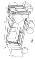
- Shown in fig. 1 is a refuse collection truck 1 which is equipped with a device according to the present invention.
- the device forms a hydraulic system which comprises: a pulling arm cylinder 2 as motor for a pulling arm 9 with which a container 7 can be placed onto and removed from the supporting surface of a truck 10; a slide cylinder 3 as motor for a slide 8 placed hingedly in container 7 in order to displace in forward direction refuse tipped into the container 7; a valve cylinder 4 as motor for a flap 11 arranged hingedly on container 7 in order to close and open the container; and a first loading cylinder 5 and a second loading cylinder 6 as motors for a lifting and tipping device 12 with which refuse bins 13 can be discharged into container 7.
- the lines run from the cylinders 2-6 to the control means on the truck 10 and connections (not shown) run from the control buttons to the control means via quick-detachable couplings (not shown) in order to enable simple placing and removal of container 10 on and off the chassis of truck 10.
- Optimum use is hereby further made of the space available in container 7 and only components of the device according to the present invention are arranged in and on container 7 which are relatively inexpensive and not susceptible to malfunction in relation to for instance a source of medium under pressure.
- a fully laden container 7 can be removed simply and a new empty container placed so that operations are interrupted for only a minimized time period once a container has been fully loaded.
- FIG. 2 Shown schematically in fig. 2 is an embodiment of a device in the application according to the present invention shown in fig. 1.
- the device substantially comprises: pumps 15 as sources of medium under pressure, feed lines 16, control blocks 18 as control means, through-feed lines 19, drain lines 20 and an oil tank 21.
- the pumps 15 are embodied in the embodiment shown here as discharge pumps for pumping through an adjustable quantity of oil per unit of time.
- Pumps 15 draw off oil from oil tank 21 to send a minimum flow, which amounts for instance to 6 litres per minute, to the control blocks 18 via feed lines 16.
- filters 17 are arranged in feed lines 16.
- the pumps 15 supply the minimum flow when none of the cylinders 2-6 is operating. In this case this minimum flow is returned to oil tank 21 via drain lines 20.
- control button 23 is energized, whereby in the control block 18 the through-feed line 19 is placed into connection with the feed line 16, for instance via a system of servo-valves.
- This can be effected for instance by means of a simple valve.
- a control pressure for supplying to a closing valve 22 over a closing line 24 is herein drawn off in order to close the drain line 20 by means of the closing valve 22.
- a controlling pressure for supplying to the pump 15 over a feedback line 25 is also drawn off in control block 18 in order to control pump 15.
- the detecting means are therefore formed by the taps in control block 18. In response to this controlling pressure over feedback line 25 the pump 15 produces a higher output.
- the pressure in through-feed line 19 will then increase rapidly as will the output related thereto which is produced by the source 15, here in the form of volume/unit of time, for instance 60 litres/min., until the pressure in through-feed line 19 is sufficient to cause the pulling arm cylinder 2 with the load acting thereon to function.
- the control pressure in feedback line 25 does not increase further herein, so that the pump 15 produces a constant output.
- pressure limiting means are preferably arranged in control blocks 18.
- the pump 15 is controlled by the control block via the feedback line 25 to cause the pressure to decrease.
- the excess oil is herein returned to oil tank 21 via control block 18 and a second drain line 27 in which an oil cooler 26 is accommodated.
- the power required thereby can be supplied simultaneously or successively to one or more than one of the cylinders 2-6 associated with one of the control blocks 18.
- the only limitation is that the power required by the motors to be set into combined operation may not exceed the maximum output of the pump.
- a different pressure with an associated flow rate can herein be provided with the pumps 15 to each of the motors which are to be set into operation separately but simultaneously, provided the total required flow rate for one of the control blocks 18 does not exceed the output of the associated pump 15.
- Control blocks 18 are provided with pressure limiting valves (not shown) in order to ensure that the pressure in through-feed line 19 does not rise so quickly to a high value such that the piston will move in the cylinder in juddering manner or too rapidly.
- the first loading cylinder 5 and the second loading cylinder 6 of the loading device 12 are suitable to each separately discharge a refuse bin 13 as shown in fig. 1 or to jointly discharge a larger refuse bin (not shown). It is desirable herein that a large refuse bin be discharged more slowly and gradually than a smaller refuse bin 13.
- control blocks 18 for the first loading cylinder 5 and the second loading cylinder 6 of the lifting and tipping device 12 are accordingly provided with pressure limiting means, wherein the operation thereof depends on the operational situation of lifting and tipping device 12, wherein a single large refuse bin is being discharged using both loading cylinders 5, 6 or smaller refuse bins 13 are being discharged using one of the loading cylinders 5, 6.
- the embodiment shown in fig. 3 of a device according to the present invention corresponds closely with that shown in fig. 2.
- the device comprises only one pump 15 and one control block 18.
- Such a device can be applied particularly advantageously when the cylinders 2-6 for driving require a comparatively low power which is smaller than the output of the pump or when a pump with a relatively high output is available.
- fig. 2 For the operation of the device further reference is made to the description of fig. 2.
- hydraulic feedback lines 25 are used to control the pumps 15 wherein it must be noted that within the scope of the present invention use can also be made of connections carrying electric signals.
- the control block herein contains detecting means and control means for generating such an electric control signal for the pumps 15. It is otherwise noted here that the motors for driving are not limited to cylinders but comprise all motors for hydraulic driving. Other embodiments are also possible within the scope of the present invention.
Landscapes
- Engineering & Computer Science (AREA)
- Mechanical Engineering (AREA)
- Physics & Mathematics (AREA)
- Fluid Mechanics (AREA)
- General Engineering & Computer Science (AREA)
- Fluid-Pressure Circuits (AREA)
- Operation Control Of Excavators (AREA)
- Refuse-Collection Vehicles (AREA)
Claims (6)
- Dispositif comprenant : au moins deux moteurs fonctionnant séparément (2-6) pour un entraínement hydraulique ; au moins une source susceptible d'être commandée (15) d'un milieu sous pression ; des lignes (16-19) pour guider le milieu sous pression à partir de la source (15) vers chacun des moteurs (2-6) ; des moyens de fonctionnement (23) pour alimenter de manière sélective le fluide hydraulique vers au moins l'un des moteurs ; des moyens de détection pour détecter l'actionnement des moyens de fonctionnement (23) ; et des moyens de commande (18) pour commander la source (15) dans le but de fournir le milieu sous pression requis de manière spécifique par le moteur (2-6) pour sa mise en fonctionnement lorsque l'actionnement des moyens de fonctionnement est détecté, caractérisé en ce que la source (15) est disposée de manière à générer une pression minimale dans un état non chargé, où ladite pression minimale est déchargée via une ligne de décharge (20) connectée aux moyens de commande, où les moyens de commande comprennent une ligne d'alimentation en retour hydraulique (25) pour la pression dépendant de la commande de la source, où la ligne de décharge comprend des moyens formant soupape (22), qui sont susceptibles d'être)fermés en réaction à l'actionnement de l'un des moteurs (2-6), et où les moyens de commande (18) sont disposés de manière à augmenter la pression dans la ligne d'alimentation en retour en réaction à l'actionnement d'au moins un des moteurs (2-6) et au chargement du moteur concerné.
- Dispositif selon la revendication 1, caractérisé en ce que les moyens de détection et les moyens de commande (18) forment une unité avec les moyens de fonctionnement (23) pour chacun des moteurs (2-6).
- Dispositif selon la revendication 2, caractérisé en ce qu'au moins deux unités sont connectées conjointement à la source (15) au moyen d'une ligne (16) et d'une ligne d'alimentation en retour (25).
- Dispositif selon l'une quelconque des revendications précédentes, caractérisé en ce que les moyens de commande (18) comprennent des moyens de limitation de la pression dépendant de l'état de fonctionnement souhaité des moteurs (2-6) pour l'entraínement.
- Camion (1), tel qu'un camion de collecte de déchets, comprenant un châssis (10) et un groupe motopropulseur assurant la propulsion, caractérisé en ce que le camion est muni d'un dispositif selon l'une quelconque des revendications précédentes, dans lequel la source (15) du milieu sous pression est couplée mécaniquement au groupe motopropulseur.
- Camion selon la revendication 5, dans lequel un conteneur séparé (7) peut être placé sur un châssis de camion, caractérisé en ce que sur le conteneur sont disposés au moins des lignes, des moteurs, des boutons de commande faisant partie des moyens de fonctionnement (23) et des moyens de couplage détachables rapidement, dans lequel les lignes et les boutons de commande (23) peuvent être placés en connexion via les moyens de couplage détachables rapidement avec les moyens de commande (18) et les moyens de détection durant le placement du conteneur sur le châssis du camion.
Applications Claiming Priority (2)
| Application Number | Priority Date | Filing Date | Title |
|---|---|---|---|
| NL1001814A NL1001814C2 (nl) | 1995-12-04 | 1995-12-04 | Hydraulisch systeem. |
| NL1001814 | 1995-12-04 |
Publications (2)
| Publication Number | Publication Date |
|---|---|
| EP0778228A1 EP0778228A1 (fr) | 1997-06-11 |
| EP0778228B1 true EP0778228B1 (fr) | 2002-06-19 |
Family
ID=19761972
Family Applications (1)
| Application Number | Title | Priority Date | Filing Date |
|---|---|---|---|
| EP96203437A Expired - Lifetime EP0778228B1 (fr) | 1995-12-04 | 1996-12-04 | Système hydraulique |
Country Status (4)
| Country | Link |
|---|---|
| EP (1) | EP0778228B1 (fr) |
| AT (1) | ATE219457T1 (fr) |
| DE (1) | DE69621899T2 (fr) |
| NL (1) | NL1001814C2 (fr) |
Families Citing this family (2)
| Publication number | Priority date | Publication date | Assignee | Title |
|---|---|---|---|---|
| US11042745B2 (en) | 2018-04-23 | 2021-06-22 | Oshkosh Corporation | Refuse vehicle control system |
| US10859167B2 (en) | 2018-05-22 | 2020-12-08 | Oshkosh Corporation | Refuse vehicle body assembly |
Family Cites Families (5)
| Publication number | Priority date | Publication date | Assignee | Title |
|---|---|---|---|---|
| US5073091A (en) * | 1989-09-25 | 1991-12-17 | Vickers, Incorporated | Power transmission |
| WO1992006306A1 (fr) * | 1990-09-28 | 1992-04-16 | Hitachi Construction Machinery Co., Ltd. | Systeme de commande pour pompe hydraulique |
| DE4244516C1 (de) * | 1992-12-30 | 1994-04-21 | Hausherr & Soehne Rudolf | Anfahrüberwachungseinrichtung für eine hydraulisch angetriebene Maschine |
| US5470187A (en) * | 1993-09-09 | 1995-11-28 | Galion Solid Waste Equipment Co., Inc. | Front-side lifting and loading apparatus |
| DE9318647U1 (de) * | 1993-12-06 | 1994-02-17 | Herion-Werke KG, 70736 Fellbach | Hydraulische Steuerungs-Anordnung |
-
1995
- 1995-12-04 NL NL1001814A patent/NL1001814C2/nl not_active IP Right Cessation
-
1996
- 1996-12-04 AT AT96203437T patent/ATE219457T1/de not_active IP Right Cessation
- 1996-12-04 EP EP96203437A patent/EP0778228B1/fr not_active Expired - Lifetime
- 1996-12-04 DE DE69621899T patent/DE69621899T2/de not_active Expired - Fee Related
Also Published As
| Publication number | Publication date |
|---|---|
| DE69621899D1 (de) | 2002-07-25 |
| DE69621899T2 (de) | 2003-02-20 |
| EP0778228A1 (fr) | 1997-06-11 |
| ATE219457T1 (de) | 2002-07-15 |
| NL1001814C2 (nl) | 1997-06-10 |
Similar Documents
| Publication | Publication Date | Title |
|---|---|---|
| US6098967A (en) | Level control arrangement for vehicles having air springs | |
| CN103459727B (zh) | 用于蓄充蓄能器的设备 | |
| US9273700B2 (en) | Pressure medium supply arrangement | |
| US5794734A (en) | Method and apparatus for supplying driving energy to vehicle subassemblies | |
| US4354693A (en) | Vehicle height adjusting device | |
| US20210001679A1 (en) | Compressed air supply installation for operating a pneumatic installation, method and vehicle | |
| EP0778228B1 (fr) | Système hydraulique | |
| US4173424A (en) | Automatic packing system for refuse vehicle | |
| US6368046B1 (en) | Modulation of ejector pumps to provide uniform and controllable ejector speed during ejector stroke for articulated trucks and the like having ejector type dump mechanism | |
| EP0451274A1 (fr) | Unite de commande hydraulique | |
| US6688834B1 (en) | Self-contained hydraulic power unit | |
| EP0844198A1 (fr) | Dispositif pour soulever et/ou faire basculer des récipients | |
| US7444808B2 (en) | Hydraulic system | |
| KR0179634B1 (ko) | 자동차용 배터리 공급장치 | |
| US20030041596A1 (en) | Hydraulic system with multiple-pressure relief limits | |
| US7264318B2 (en) | Brake pressure control arrangement | |
| JP2000281275A (ja) | 油圧式グラブバケットの油圧制御回路 | |
| JP3633995B2 (ja) | 塵芥収集車の塵芥圧縮装置 | |
| JPS6234827A (ja) | ダンプ車 | |
| CN212672135U (zh) | 一种渣土车用全液压密闭篷布机构限位装置 | |
| JPS61162402A (ja) | 塵芥収集車の油圧制御装置 | |
| JP2922262B2 (ja) | 麈芥収集車の油圧制御装置 | |
| JP2559573Y2 (ja) | 塵芥収集車の油圧制御装置 | |
| KR100375373B1 (ko) | 압축천연가스 버스용 가스 미터링 밸브의 오일 배수 시스템 | |
| JPH0344726Y2 (fr) |
Legal Events
| Date | Code | Title | Description |
|---|---|---|---|
| PUAI | Public reference made under article 153(3) epc to a published international application that has entered the european phase |
Free format text: ORIGINAL CODE: 0009012 |
|
| AK | Designated contracting states |
Kind code of ref document: A1 Designated state(s): AT BE CH DE DK ES FR GB GR IE IT LI LU MC NL PT SE |
|
| RBV | Designated contracting states (corrected) |
Designated state(s): AT BE CH DE DK ES FR GB GR IE IT LI LU MC NL PT SE |
|
| 17P | Request for examination filed |
Effective date: 19971203 |
|
| 17Q | First examination report despatched |
Effective date: 19990329 |
|
| GRAG | Despatch of communication of intention to grant |
Free format text: ORIGINAL CODE: EPIDOS AGRA |
|
| GRAG | Despatch of communication of intention to grant |
Free format text: ORIGINAL CODE: EPIDOS AGRA |
|
| GRAH | Despatch of communication of intention to grant a patent |
Free format text: ORIGINAL CODE: EPIDOS IGRA |
|
| GRAH | Despatch of communication of intention to grant a patent |
Free format text: ORIGINAL CODE: EPIDOS IGRA |
|
| GRAA | (expected) grant |
Free format text: ORIGINAL CODE: 0009210 |
|
| AK | Designated contracting states |
Kind code of ref document: B1 Designated state(s): AT BE CH DE DK ES FR GB GR IE IT LI LU MC NL PT SE |
|
| PG25 | Lapsed in a contracting state [announced via postgrant information from national office to epo] |
Ref country code: LI Free format text: LAPSE BECAUSE OF FAILURE TO SUBMIT A TRANSLATION OF THE DESCRIPTION OR TO PAY THE FEE WITHIN THE PRESCRIBED TIME-LIMIT Effective date: 20020619 Ref country code: IT Free format text: LAPSE BECAUSE OF FAILURE TO SUBMIT A TRANSLATION OF THE DESCRIPTION OR TO PAY THE FEE WITHIN THE PRESCRIBED TIME-LIMIT;WARNING: LAPSES OF ITALIAN PATENTS WITH EFFECTIVE DATE BEFORE 2007 MAY HAVE OCCURRED AT ANY TIME BEFORE 2007. THE CORRECT EFFECTIVE DATE MAY BE DIFFERENT FROM THE ONE RECORDED. Effective date: 20020619 Ref country code: GR Free format text: LAPSE BECAUSE OF FAILURE TO SUBMIT A TRANSLATION OF THE DESCRIPTION OR TO PAY THE FEE WITHIN THE PRESCRIBED TIME-LIMIT Effective date: 20020619 Ref country code: CH Free format text: LAPSE BECAUSE OF FAILURE TO SUBMIT A TRANSLATION OF THE DESCRIPTION OR TO PAY THE FEE WITHIN THE PRESCRIBED TIME-LIMIT Effective date: 20020619 Ref country code: BE Free format text: LAPSE BECAUSE OF FAILURE TO SUBMIT A TRANSLATION OF THE DESCRIPTION OR TO PAY THE FEE WITHIN THE PRESCRIBED TIME-LIMIT Effective date: 20020619 Ref country code: AT Free format text: LAPSE BECAUSE OF FAILURE TO SUBMIT A TRANSLATION OF THE DESCRIPTION OR TO PAY THE FEE WITHIN THE PRESCRIBED TIME-LIMIT Effective date: 20020619 |
|
| REF | Corresponds to: |
Ref document number: 219457 Country of ref document: AT Date of ref document: 20020715 Kind code of ref document: T |
|
| REG | Reference to a national code |
Ref country code: GB Ref legal event code: FG4D |
|
| REG | Reference to a national code |
Ref country code: CH Ref legal event code: EP |
|
| REG | Reference to a national code |
Ref country code: IE Ref legal event code: FG4D |
|
| REF | Corresponds to: |
Ref document number: 69621899 Country of ref document: DE Date of ref document: 20020725 |
|
| PG25 | Lapsed in a contracting state [announced via postgrant information from national office to epo] |
Ref country code: SE Free format text: LAPSE BECAUSE OF FAILURE TO SUBMIT A TRANSLATION OF THE DESCRIPTION OR TO PAY THE FEE WITHIN THE PRESCRIBED TIME-LIMIT Effective date: 20020919 Ref country code: DK Free format text: LAPSE BECAUSE OF FAILURE TO SUBMIT A TRANSLATION OF THE DESCRIPTION OR TO PAY THE FEE WITHIN THE PRESCRIBED TIME-LIMIT Effective date: 20020919 |
|
| PG25 | Lapsed in a contracting state [announced via postgrant information from national office to epo] |
Ref country code: PT Free format text: LAPSE BECAUSE OF FAILURE TO SUBMIT A TRANSLATION OF THE DESCRIPTION OR TO PAY THE FEE WITHIN THE PRESCRIBED TIME-LIMIT Effective date: 20020923 |
|
| ET | Fr: translation filed | ||
| PG25 | Lapsed in a contracting state [announced via postgrant information from national office to epo] |
Ref country code: LU Free format text: LAPSE BECAUSE OF NON-PAYMENT OF DUE FEES Effective date: 20021204 Ref country code: IE Free format text: LAPSE BECAUSE OF NON-PAYMENT OF DUE FEES Effective date: 20021204 |
|
| PG25 | Lapsed in a contracting state [announced via postgrant information from national office to epo] |
Ref country code: ES Free format text: LAPSE BECAUSE OF FAILURE TO SUBMIT A TRANSLATION OF THE DESCRIPTION OR TO PAY THE FEE WITHIN THE PRESCRIBED TIME-LIMIT Effective date: 20021220 |
|
| REG | Reference to a national code |
Ref country code: CH Ref legal event code: PL |
|
| PLBE | No opposition filed within time limit |
Free format text: ORIGINAL CODE: 0009261 |
|
| STAA | Information on the status of an ep patent application or granted ep patent |
Free format text: STATUS: NO OPPOSITION FILED WITHIN TIME LIMIT |
|
| 26N | No opposition filed |
Effective date: 20030320 |
|
| PG25 | Lapsed in a contracting state [announced via postgrant information from national office to epo] |
Ref country code: MC Free format text: LAPSE BECAUSE OF NON-PAYMENT OF DUE FEES Effective date: 20030701 |
|
| REG | Reference to a national code |
Ref country code: IE Ref legal event code: MM4A |
|
| PGFP | Annual fee paid to national office [announced via postgrant information from national office to epo] |
Ref country code: GB Payment date: 20051201 Year of fee payment: 10 |
|
| PGFP | Annual fee paid to national office [announced via postgrant information from national office to epo] |
Ref country code: FR Payment date: 20051229 Year of fee payment: 10 Ref country code: DE Payment date: 20051229 Year of fee payment: 10 |
|
| PGFP | Annual fee paid to national office [announced via postgrant information from national office to epo] |
Ref country code: NL Payment date: 20051230 Year of fee payment: 10 |
|
| PG25 | Lapsed in a contracting state [announced via postgrant information from national office to epo] |
Ref country code: NL Free format text: LAPSE BECAUSE OF NON-PAYMENT OF DUE FEES Effective date: 20070701 |
|
| PG25 | Lapsed in a contracting state [announced via postgrant information from national office to epo] |
Ref country code: DE Free format text: LAPSE BECAUSE OF NON-PAYMENT OF DUE FEES Effective date: 20070703 |
|
| GBPC | Gb: european patent ceased through non-payment of renewal fee |
Effective date: 20061204 |
|
| NLV4 | Nl: lapsed or anulled due to non-payment of the annual fee |
Effective date: 20070701 |
|
| REG | Reference to a national code |
Ref country code: FR Ref legal event code: ST Effective date: 20070831 |
|
| PG25 | Lapsed in a contracting state [announced via postgrant information from national office to epo] |
Ref country code: GB Free format text: LAPSE BECAUSE OF NON-PAYMENT OF DUE FEES Effective date: 20061204 |
|
| PG25 | Lapsed in a contracting state [announced via postgrant information from national office to epo] |
Ref country code: FR Free format text: LAPSE BECAUSE OF NON-PAYMENT OF DUE FEES Effective date: 20070102 |