EP0778231A2 - Dispositif d'alignement et d'alimentation de pièces - Google Patents
Dispositif d'alignement et d'alimentation de pièces Download PDFInfo
- Publication number
- EP0778231A2 EP0778231A2 EP96119066A EP96119066A EP0778231A2 EP 0778231 A2 EP0778231 A2 EP 0778231A2 EP 96119066 A EP96119066 A EP 96119066A EP 96119066 A EP96119066 A EP 96119066A EP 0778231 A2 EP0778231 A2 EP 0778231A2
- Authority
- EP
- European Patent Office
- Prior art keywords
- parts
- oriented
- incorrectly
- discriminating
- removing means
- Prior art date
- Legal status (The legal status is an assumption and is not a legal conclusion. Google has not performed a legal analysis and makes no representation as to the accuracy of the status listed.)
- Granted
Links
Images



Classifications
-
- B—PERFORMING OPERATIONS; TRANSPORTING
- B65—CONVEYING; PACKING; STORING; HANDLING THIN OR FILAMENTARY MATERIAL
- B65G—TRANSPORT OR STORAGE DEVICES, e.g. CONVEYORS FOR LOADING OR TIPPING, SHOP CONVEYOR SYSTEMS OR PNEUMATIC TUBE CONVEYORS
- B65G47/00—Article or material-handling devices associated with conveyors; Methods employing such devices
- B65G47/22—Devices influencing the relative position or the attitude of articles during transit by conveyors
- B65G47/24—Devices influencing the relative position or the attitude of articles during transit by conveyors orientating the articles
- B65G47/256—Devices influencing the relative position or the attitude of articles during transit by conveyors orientating the articles removing incorrectly orientated articles
-
- B—PERFORMING OPERATIONS; TRANSPORTING
- B65—CONVEYING; PACKING; STORING; HANDLING THIN OR FILAMENTARY MATERIAL
- B65G—TRANSPORT OR STORAGE DEVICES, e.g. CONVEYORS FOR LOADING OR TIPPING, SHOP CONVEYOR SYSTEMS OR PNEUMATIC TUBE CONVEYORS
- B65G2203/00—Indexing code relating to control or detection of the articles or the load carriers during conveying
- B65G2203/04—Detection means
- B65G2203/042—Sensors
Definitions
- the present invention relates generally to a parts feeder of the type wherein parts held in a rotating drum provided in place of a conventional bowl are fed in order along a linear passage at high speed and with reliability for conveyance to the next processing operation, and more particularly to a parts feeder which is suitable for use with various parts having irregular cross sections and requiring orientation in conveyance.
- a parts feeder as disclosed in Japanese Patent Laid-open Publication No. HEI 5-178447 is generally used for conveyance of small parts.
- the disclosed parts feeder is of the bowl type including a bottomed vibrating bowl with a spiral parts feed passage on an inside wall surface thereof, and a plate-like chute interconnecting an outlet of the parts feed passage in the bowl and a parts supplying portion of the next processing station.
- U.S. Patent No. 2,052,179 discloses a parts feeder for feeding fastener elements for a slide fastener.
- the disclosed parts feeder includes a horizontal horizontal axis, a downwardly inclined tubular chute extending from the inside of the horizontal drum to the outside of the same along the axis of the horizontal drum.
- An inner cylindrical drum driven to rotate in one direction about a substantially wall surface of the horizontal drum is provided with a plurality of wing plates circumferentially spaced at predetermined intervals and projecting radially inwardly at predetermined angles toward the axis of the horizontal drum.
- the parts held in batches in the horizontal drum are scooped or taken up by the wing plates and when the wing plates reach an upper oblique position of the drum, the parts slide down from the wing plates onto a tray and then received in a longitudinal slit formed in an upper surface of the tubular chute.
- the parts slides down along the slit of the tubular chute for conveyance to a delivery chute connected to the next processing station.
- the parts will to move into the internal space of the tubular chute and then fall down to the outside of the tubular chute through a discharge hole formed in a portion of a bottom surface of the tubular chute.
- the bowl type parts feeder shown in Japanese Patent Laid-open Publication No. HEI 5-178447 has a drawback in that since conveyance of the parts relies on vibration of the bowl in the circumferential direction thereof, not only the parts are unlikely to move or advance smoothly along the spiral feed passage, but also it is difficult to advance the parts on the feed passage smoothly.
- the bowl type part feeder therefore, has a limitation or difficulty in increasing the parts conveyance speed. Furthermore, it is doubtful that the parts can be reliably transferred from the spiral feed passage to the plate-like chute.
- the drum-type parts feeder disclosed in U.S. Patent No. 2,052,179 has no means for positively advancing the parts. Instead, the parts simply slide down the chute by their own weights while they are guided in the slit of the tubular chute. Accordingly, smooth conveyance of the parts is difficult to achieve, and the parts conveyance speed cannot be increased. Further, depending on the shape of parts to be conveyed, the number of parts which can be received in the slit may be limited, thus lowering the productivity.
- the disclosed drum type parts feeder cannot make a discrimination between the front and the reverse of the respective parts to be fed, so that it can not recognize and remove parts in reverse or wrong postures. Accordingly, the parts feeder is not suitable for use with parts, such as fastener elements for a slide fastener, which require orientation in conveyance.
- an object of the present invention to provide an orientation parts feeder which is capable of feeding parts reliably and smoothly while keeping them in a desired posture or orientation, and is able to realize a high speed conveyance and a reliable operation over a prolonged period of use.
- an orientation parts feeder of this invention for successively feeding parts each having an irregular cross section while keeping them in identical postures, comprising: a transfer chute of an elongated rectangular bar having a longitudinal parts guide channel in its one side; a vibration generating means supporting thereon the transfer chute for vibrating the transfer chute in a longitudinal direction thereof; and a first and a second incorrectly-oriented-parts discriminating and removing means disposed on the transfer chute in succession toward a downstream end of the parts guide channel for discriminating and removing parts of undesired postures from the parts guide channel.
- the first incorrectly-oriented-parts discriminating and removing means discriminates and removes the parts of the undesired postures while they are fed down the parts guide channel
- the second incorrectly-oriented-parts discriminating and removing means detects the parts of the undesired postures which have passed the first incorrectly-oriented-parts discriminating and removing means, so as to stop the detected parts of the undesired posture and then removes the thus stopped parts.
- the transfer chute is preferably inclined downward toward a direction of conveyance of the parts.
- the first incorrectly-oriented-parts discriminating and removing means includes at least two parts detecting means, and a single parts removing means.
- said at least two parts detecting-means are positioned such that if any of the parts in conveyance has a desired posture, it is detected by each one of said at least two parts detecting means separately, and if any of the parts in conveyance has an undesired posture, it is detected simultaneously by said at least two parts detecting means.
- the parts removing means includes an air blast mechanism operable, in response to coexisting detection signals from said at least two parts detecting means, to eject air against the parts of the undesired posture.
- the second incorrectly-oriented-parts discriminating and removing means preferably includes a parts blocking member disposed at the parts guide channel for adjusting a restricted passageway of the parts to prevent passage of the parts of the undesired postures while allowing the passage of the parts of a desired posture, a parts removing member retractably movable into the restricted passageway defined by the parts blocking member, a parts detecting means disposed downstream of the parts removing means for detecting the arrival of the parts, and an actuating means for allowing the parts removing member to move into the restricted passageway when detection of the arrival of each of the parts by the parts detecting means does not take place within a predetermined time period.
- the transfer chute If one of the parts being fed down the transfer chute has an undesired posture or orientation, light beams projected from two light projectors toward a light detector (constituting jointly with the light projectors the aforesaid at least two parts detecting means of the first incorrectly-oriented parts discriminating and removing means) are simultaneously blocked by one of the parts. In this instance, the luminous energy detected by the light detector falls below a predetermined value. If such a low luminous energy condition still continues even after a lapse of the predetermined time period, the air blast mechanism is activated to eject compressed air toward the one of the parts for a predetermined period of time.
- the greater part of the incorrectly oriented parts i.e., parts having undesired postures
- the greater part of the incorrectly oriented parts are discharged from the parts guide channel to the outside of the orientation parts feeder as they travel down the parts guide channel.
- a correctly oriented parts i.e., parts having the desired posture, coming just before or next to the incorrectly oriented parts, are either removed together with the incorrectly oriented part, or forcibly displaced or incorrectly oriented to assume an undesired postures by the effect of the compressed air ejected from the air blast mechanism of the first incorrectly-oriented-parts discriminating and removing means.
- each of the forcibly incorrectly oriented parts after having passed the first incorrectly-oriented-parts discriminating and removing means passes the second incorrectly-oriented-parts discriminating and removing means.
- the orientation parts feeder may further include a parts orienting means disposed on the parts guide channel at an upstream side of the first and second incorrectly-oriented-parts discriminating and removing means for orienting the parts into the desired posture.
- the parts orienting means preferably comprises an air blast mechanism.
- the downstream end of the transfer chute may be connected via an arcuate parts-feed-direction changing passage to a vertical chute for conveyance of the parts to the next processing operation.
- the first and second incorrectly-oriented-parts discriminating and removing means are disposed in succession on a downstream end portion of the transfer chute.
- the arcuate parts-feed-direction changing passage is a part or segment of a circular groove formed in a curved surface of a hollow circular truncated cone.
- the hollow circular truncated cone is divided into a plurality of segment members each having an arcuate groove which forms the parts-feed-direction changing passage.
- the orientation parts feeder may further include a parts discharge hole formed in a guide surface of the parts guide channel at a position between the second incorrectly-oriented-parts discriminating and removing means and the arcuate parts-feed-direction changing passage so as to allow parts of undesired postures which could not have been removed even by the second incorrectly-oriented-parts discriminating and removing means, to fall down by their own weights to the outside of the transfer chute.
- a parts discharge hole formed in a guide surface of the parts guide channel at a position between the second incorrectly-oriented-parts discriminating and removing means and the arcuate parts-feed-direction changing passage so as to allow parts of undesired postures which could not have been removed even by the second incorrectly-oriented-parts discriminating and removing means, to fall down by their own weights to the outside of the transfer chute.
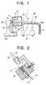
- FIG. 1 shows, in side view with parts in cross section, a general construction of the orientation parts feeder 1 according to the present invention.
- This embodiment illustrates an apparatus for continuously conveying metal fastener elements for a slide fastener.
- the orientation parts feeder 1 includes a rotating drum 10 rotatable about a rotating shaft 14 inclined upwardly at a slight angle to the horizontal, an electric motor 20 for rotatably driving the rotating drum 10, a transfer chute 30 of in a form of an elongated rectangular bar along which a multiplicity of fastener elements 2 held in the rotating drum 10 are fed or conveyed to the outside of the rotating drum 10 while keeping a desired posture or orientation in a manner described later, a vibrating unit 40 for vibrating the transfer chute 30 in its longitudinal direction, and first and second incorrectly-oriented-parts discriminating and removing units 50 and 55 for removing fastener elements 2 having undesired postures or orientations from the transfer chute 30 while they are fed down the transfer chute 30.
- the rotating drum 10 has a hollow cylindrical shape and includes a bottom plate 11 at one end, and an open end 12 at the opposite end.
- the rotating drum 10 includes a plurality of wing plates 13 extending parallel to the axis of rotation of the drum 10 and being circumferentially spaced at regular intervals, and projecting radially inwardly from an inner cylindrical wall of the drum 10 toward the axis.
- the thus constructed rotating drum 10 is rotatably disposed, with its bottom plate 11 facing obliquely and downwardly at a predetermined angle, and with its open end 12 facing upwardly and obliquely.
- the rotating shaft 14 projects outwardly from the center of the bottom plate 11 of the rotating drum 10 and is rotatably supported on an upper supporting portion 15a of a support frame 15 while keeping the predetermined angle of inclination.
- the rotating shaft 14 is connected by an endless belt 16 to the electric motor 20 disposed on a lower base 15b of the support frame 15.
- the electric motor 20 may be provided with a non-illustrated built-in speed reducer, not shown.
- the transfer chute 30 is composed of an elongated rectangular bar, as described above, and has one end (upstream end) inserted into the rotating drum 10 through the open end 12 and terminating short of the bottom plate 11.
- the opposite end (downstream end) of the chute 30 is connected via an arcuate (quarter-circular) parts-feed-direction changing member 60 to a vertical chute 61 leading to the next processing station.
- the transfer chute 30 as a whole is inclined slightly downwardly toward the joint portion between itself and the vertical chute 61. Further, the transfer chute 30 has a front surface tilted at an angle of 45° - 60° and having a stepped longitudinal parts guide passage thereon and extending throughout the length of the transfer chute 30.
- the quarter-circular parts-feed-direction changing member 60 in this embodiment has a longitudinal parts-feed-direction changing passage 60a formed simply by cutting.
- FIG. 8 schematically illustrates the manner in which the parts-feed-direction changing member 60 is produced.
- a short cylindrical metal material 60B while being rotated about its axis is shaped into a hollow circular truncated cone by means of a bite 62, during which a continuous circular groove 60A is formed or cut in an intermediate portion of a circumferential surface of the truncated cone.
- the grooved hollow circular truncated cone thus obtained is then divided into four equal segments each of which forms the aforesaid arcuate (quarter-circular) parts-feed-direction changing member 60.
- FIG. 9 is a schematic perspective view showing the transfer chute 30 and the vertical chute 61 joined together with the parts-feed-direction changing member 60 disposed therebetween.
- the fastener elements 2 are first slid down in the parts guide channel 31 while being supported in a backward tilted position by the tilted front surface of the parts guide channel 31. Then they are gradually placed into an upright position as they travel through the arcuate passage 60a in the parts-feed-direction changing member 60, and finally slid down the vertical chute 61.
- the transfer chute 30 in order to advance the fastener elements 2 positively along the parts guide channel 31 of the transfer chute 30 as soon as they are received in the parts guide channel 31 disposed inside the rotating drum 10, the transfer chute 30 is vibrated in the longitudinal direction thereof.
- the transfer chute 30 is supported by the vibrating unit 40 at the outside of the rotating drum 10 so that the transfer chute 30 is directly vibrated by the vibrating unit 40.
- the vibrating unit 40 may be either an electromagnetic vibrator or a mechanical vibrator, both being readily available in the market.
- the first and second incorrectly-oriented-parts discriminating and removing means 50, 55 are disposed in succession on a downstream end portion of the parts guide channel 31 of the transfer chute 30 for discriminating and removing the fastener elements 2 being conveyed in incorrect postures other than the predetermined desired posture.
- Such a series arrangement of the first and second incorrectly-oriented-parts discriminating and removing means 50, 55 at the downstream end portion of the parts guide channel 31 of the transfer chute 30 is applied for the purpose of securing a reliable orientation of the parts (fastener elements 2) at the final stage of transport to the next processing operation.
- the first and second incorrectly oriented-parts discriminating and removing means 50, 55 perform a two-stage discrimination and removing of the incorrectly oriented parts (fastener elements 2) which will considerably improve the parts orientation accuracy. More specifically, the first incorrectly-oriented-parts discriminating and removing means 50 is provided for achieving an efficient discrimination and removing of incorrectly oriented fastener elements 2 from a multiplicity of all the correctly or incorrectly oriented fastener elements 2 fed in succession down the transfer chute 30, and the second incorrectly-oriented-parts discriminating and removing means 55 is provided for achieving a reliable discrimination and removing of the incorrectly oriented fastener elements 2 which could not have been discriminated and removed by the first incorrectly-oriented-parts discriminating and removing means 50.
- the first incorrectly-oriented-parts discriminating and removing means 50 includes a photoelectric detector 51 and an air blast mechanism (parts removing means) 54 operative in quick response to detection signals from the photoelectric detector 51 for ensuring that a incorrectly oriented fastener element 2 can be discriminated and removed efficiently at high speeds.
- the second incorrectly-oriented-parts discriminating and removing means 55 has a lower response speed than the first incorrectly-oriented-parts discriminating and removing means 50 but includes a mechanical discriminating and removing mechanism which is capable of securing a highly reliable discrimination and removing of the incorrectly oriented fastener elements 2.
- the photoelectric detectors 51 are used in combination to make a discrimination between incorrectly oriented fastener elements 2 and correctly oriented fastener elements 2. As shown in FIG.
- the discriminating mechanism of the detector 51 is composed of two light sources or projectors 52 and 52 disposed behind the tilted front face of the parts guide channel 31 at different heights or levels and spaced in the direction of conveyance of the fastener elements 2 by a predetermined distance L, and two light detectors 53, 53 disposed in confrontation with the light projectors 52, 52 for receiving light beams projected from the respective light projectors 52, 52.
- the respective levels of the first and second light projectors 52, 52 are determined such that the fastener elements 2 each having any of three different postures as shown in FIGS. 3A, 3B and 3C blocks the light beams from the first and second light projectors 52, 52 when they pass by the respective light projectors 52, 52.
- the distance L between the first and second projectors 52, 52 is determined such that a incorrectly oriented fastener element 2, namely, a fastener element 2 having an undesired posture or orientation, can be discriminated depending on a change in luminous energy received by the light detectors 53, 53 which may be caused when the incorrectly oriented fastener element 2 passes right by the first and second light projectors 52, 52'.
- FIG. 3A shows fastener elements 2 being conveyed in a desired posture or orientation.
- the fastener element 2 as it passes right by the first and second light projectors 52, 52, do never block the light beams from the first and second light projectors 52, 52, simultaneously. Instead, it blocks the light beams from the respective projectors 52, 52 separately .
- a fastener element 2 having an undesired posture or orientation shown in FIG. 3B or 3C passes right by the first and second light projectors 52, 52, the light beams from the respective light projectors 52, 52 are blocked simultaneously by the incorrectly oriented fastener element 2.
- the first and second light projectors 52', 52' are positioned in the manner described above.
- the light detectors 53, 53 sends an electric signal to a non-illustrated control unit, which, after the lapse of a predetermined time, issues a command signal to open a non-illustrated valve to activate the air blast mechanism 54.
- the air blast mechanism 54 ejects compressed air toward the forthcoming or approaching fastener element 2 for a predetermined period of time.
- the air blast mechanism 54 has an air blast hole 54a formed in the transfer chute 30 and opening to the parts guide channel 31. The air blasting time enough for the purpose is 0.08 to 0.15 second.
- the greater members of the incorrectly oriented fastener elements 2, as they travel down the parts guide channel 31, are discriminated among all the fastener elements 2 being fed in succession and then discharged from the parts guide channel 31 to the outside of the orientation parts feeder 1.
- the air blasting in fact ensures a highly efficient operation for removing the incorrectly oriented parts.
- the air blasting is continuously effected for the predetermined period of time, with the predetermined time interval or delay provided after the detection of an incorrectly oriented fastener element 2, notwithstanding that all the fastener elements 2 are not always conveyed at the same speed along the transfer chute 30 being vibrated, it may occur that the incorrectly oriented fastener element 2 passes the air nozzle 54a without being subjected to the compressed air ejected from the air nozzle 54a, or that a correctly oriented fastener element 2 coming just before or next to the incorrectly oriented fastener is blasted the compressed air to assume an undesired posture or orientation.
- the present invention further provides the second incorrectly-oriented-parts discriminating and removing means 55 disposed on the downstream side of the first incorrectly-oriented-parts discriminating and removing means 50. Since most incorrectly oriented fastener elements 2 have already been removed by the first incorrectly-oriented-parts discriminating and removing means 50, the role of the second incorrectly-oriented-parts discriminating and removing means 55 is to discriminate and remove the remaining incorrectly oriented fastener elements 2 with improved reliability.
- the second incorrectly-oriented-parts discriminating and removing means 55 may not have a high response speed but is required to have a mechanism which is capable of achieving a highly reliable discrimination and removing of the incorrectly oriented fastener elements 2 which have passed the first incorrectly-oriented-parts discriminating and removing means 50.
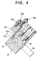
- the second incorrectly-oriented-parts discriminating and removing means 55 of the illustrated embodiment is composed of a mechanical discriminating and removing mechanism, such as shown in FIGS. 4 and 5A - 5C.
- the mechanical discriminating and removing mechanism includes a recess 32 extending from a back surface of the transfer chute 30 toward the parts guide channel 31 and terminating short of the parts guide channel 31, and a rectangular hole 32a extending from the bottom surface of the recess 32 to the front surface of the parts guide channel 31.
- the recess 32 movably receives therein an actuating rod 57 attached as a parts removing member, which is fixed to an outer end of the rod of an air cylinder 59, with a tip end portion 57a of the actuating rod 57 slidably received in the rectangular hole 32a.
- a parts blocking member 56 is slidably mounted on the front surface of the parts guide channel 31 at a position located directly above the rectangular hole 32a in such a manner that the vertical position of the parts blocking member 56 can be adjusted by an adjusting screw 56a.
- the parts blocking member 56 is a rectangular plate having at its upper end an integral projection 56b.
- the projection 56b has a screw hole in which the adjusting screw 56a is threaded.
- a lower surface of the rectangular plate-like parts blocking member 56 is composed of a taper surface 56c sloping down toward the direction of conveyance of the fastener elements 2, and a straight surface 56d extending continuously from a downstream end of the taper surface 56c.
- reference character 56e denotes a resilient adjusting mechanism which includes a compression spring (not designated) for preventing the parts blocking member 56 from being moving upwardly by the incorrectly oriented fastener element 2.
- a photoelectric parts detector 58 FIG. 1
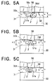
- the parts blocking member 56 defines in the parts guide channel 31 a narrowed or restricted parts passage which has a width (height) which is slightly greater than the width (height) H1 of a fastener element 2 fed in the desired posture or orientation shown in FIG. 5A, but smaller than the width (height) H2 of a fastener element 2 fed in an undesired posture or orientation shown in FIG. 5B or FIG. 5C.
- the orientation parts feeder 1 of the construction described above operates as follows.
- the electric motor 20 is driven to rotate the rotating drum 10 having a great number of fastener elements 2 therein.
- the fastener elements 2 held in the rotating drum 10 are scooped or taken up by the wing plates 13 of the rotating drum 10, and when the wing plates 13 reach an upper oblique position, the fastener elements 2 slide down the wing plates 13 and are received in an upstream portion of the parts guide channel 31 of the transfer chute 30 of which front surface is tilted backwardly at an angle of 45° to 60° degrees.
- the transfer chute 30 is vibrated in its longitudinal direction by the vibrating unit 40, so the fastener elements 2 received in the parts guide channel 31 can be smoothly advanced along the parts guide channel 31.
- the fastener elements 2 supported on a guide surface of the parts guide channel 31 have the desired posture or orientation shown in FIG. 3A and FIG. 5A, none of them are detected as incorrectly oriented fastener elements by the first and second incorrectly-oriented-parts discriminating and removing means 50, 55.
- the correctly oriented fastener elements 2 are fed smoothly into the quarter-circular parts-feed-direction changing passage 60a, then transferred therefrom into the vertical chute 61, and finally delivered to the next processing operation. Throughout the conveyance, the fastener elements 2 keep their desired posture or orientation.
- each of the incorrectly oriented fastener elements 2 simultaneously blocks both light beams from the first and second light projectors 52, 52 of the first incorrectly-oriented-parts discriminating and removing means 50. With the light beams thus blocked, luminous energy detected by the light detectors 53, 53 falls below a predetermined value. By virtue of the decrease of the detected luminous energy, the light detectors 53, 53 send an electric signal to the non-illustrated control unit which, after the lapse of the predetermined time period, issues a command signal to open the non-illustrated valve to activate the air blast mechanism 54.
- fastener elements 2 having the desired posture, coming just before or next to the incorrectly oriented fastener element 2 are either removed together with the incorrectly oriented part 2, or forcibly displaced or incorrectly oriented to assume an undesired posture, by the effect of the compressed air ejected from the first incorrectly-oriented-parts discriminating and removing means 50.
- the forcibly incorrectly oriented fastener element 2 after having passed the first incorrectly-oriented-parts discriminating and removing means 50 passes the second incorrectly-oriented-parts discriminating and removing means 55, the incorrectly oriented fastener element 2 is discriminated and removed from the parts guide channel 31 with utmost reliability.
- control unit activates the air cylinder 59 in its extending direction to project the tip end portion 57a of the actuating rod 57 outwardly from the rectangular hole 32a into the parts guide channel 31, more particularly, the restricted passage defined by the parts blocking member 56, with the result that the fastener element 2 arrested by the parts blocking block 56 is thrust off from the parts guide channel 31.
- the orientation parts feeder 1 may further include a parts orienting means 70, which is shown in FIG. 6A - 6E disposed in the parts guide channel 31 at an upstream side of the first incorrectly-oriented-parts discriminating and removing means 50.
- the parts orienting means 70 is so constructed as to correct the posture of an incorrectly oriented fastener element 2 into a predetermined desired posture while the fastener element 2 is fed along the parts guide channel 31 of the transfer chute 30, as shown in FIGS. 6B - 6E.
- the parts orienting means 70 is composed of an air blast mechanism.
- the fastener elements 2, as they are slid down along the transfer chute 30 toward the parts orienting means 70 have one of four postures shown in FIGS. 6A, 6B, 6C and 6D, respectively. Now, posture, those fastener elements 2 having other postures shown in FIGS. 6B - 6D are oriented to assume the desired posture of FIG. 6A by the parts orienting means 70.
- the air blast mechanism constituting the parts orienting means 70 includes a series of non-illustrated air nozzles formed, in a bottom surface of the parts guide channel 31 of the transfer chute 30.
- the air nozzles are inclined in such a manner that streams of air ejected from the air nozzles at a predetermined pressure are directed upwardly and obliquely at an appropriate angle as indicated by the arrows shown in each of FIGS. 6A - 6E.
- the air ejected from the lower left of the fastener element 2 flows upwardly along an upper surface of an inclined leg of the fastener element 2 and, hence, the air has no function to overturn the fastener element 2.
- the air ejected overturns the fastener element 2 in the forward or downstream direction with its legs directed leftwise of the figure so as to assume a horizontal recumbent posture as shown in FIG. 6C, then turns the fastener element 2 clockwise about its head portion to assume an inverted posture shown in FIG. 6D, and by the air further ejected from the lower left, finally further turns the fastener element 2 clockwise about the head portion to assume another horizontal recumbent posture shown in FIG. 6E where the fastener element 2 has the desired posture shown in FIG. 6A.
- One example of such means comprises, as shown in FIG. 7, a parts discharge hole 33 provided for discharging incorrectly oriented fastener elements 2 which could not have been removed by the second incorrectly-oriented-parts discriminating and removing means 55, by allowing them to fall down by their own weight from the parts discharge hole 33 to the outside of the transfer chute 30.
- the second incorrectly-oriented-parts discriminating and removing means 55 is so constructed as to detect and remove a fastener element 2 having an upright posture shown in FIG. 5B and a fastener element 2 having an inverted posture shown in FIG. 5C.
- a fastener element 2 has a horizontal recumbent posture as shown in FIG. 6C which is oriented in the opposite direction to that of the desired posture of the fastener element 2 shown in FIG. 5A
- the fastener element 2 of the undesired recumbent posture can be neither detected nor removed by the second incorrectly-oriented-parts discriminating and removing means 55.
- the parts discharge hole 33 is formed in the tilted front surface of the parts guide channel 31 at a position downstream of the second incorrectly-oriented-parts discriminating and removing means 55, such as shown in FIG. 7, so that the fastener element 2 sliding down the vibrating chute 30 with the posture shown in FIG. 6C is automatically received in the parts discharge hole 33 and hence allowed to fall down by its own weight from the parts discharge hole 33 in the parts guide channel 31 of the chute 30.
- the parts discharge hole 33 is substantially similar in shape as the fastener element 2 fed in the undesired posture of FIG. 6C and is larger in size than the same fastener element 2. With the parts discharge hole 33 thus profiled, a fastener element 2 having a desired posture indicated by the broken line shown in FIG. 7 can pass the parts discharge hole 33 smoothly while it is supported by the guide surfaces of the parts guide channel 31. On the other hand, when the fastener element 2 sliding down the transfer chute 30 in the undesired recumbent posture of FIG. 6C arrives at the parts discharge hole 33, it loses a support of the guide surfaces of the parts guide channel 31 and hence fall down by its own weight from the parts discharge hole 33 to the outside of the parts guide channel 31. Thus, the fastener elements 2 of the undesired recumbent posture which could not have been removed by the second incorrectly-oriented-parts discriminating and removing means 55 can be removed completely.
- first and second incorrectly-oriented-parts discriminating and removing means 50, 55, the parts orienting means 70, and the parts discharge hole 33 can be modified in various ways according to the type and shape of parts used.
- orientation parts feeder 1 of this invention As described above, according to the orientation parts feeder 1 of this invention, a great number of parts (fastener elements 2, for example) held in a substantially horizontally supported rotating drum 10 are scooped or taken up by a plurality of wing plates 13 provided on a cylindrical inner wall of the rotating drum 10. Then the parts are dropped onto a guide surface of a longitudinal parts guide channel 31 in a linear transfer chute 30 while being vibrated in the longitudinal direction. Thereafter, the parts are positively advanced down along the vibrating transfer chute 30.
- the orientation parts feeder 1 thus constructed has an extremely high conveyance speed.
- the orientation parts feeder 1 of this invention further includes a first and a second incorrectly-oriented-parts discriminating and removing means 50, 55 disposed in succession on a downstream end portion of the transfer chute 31.
- the first incorrectly-oriented-parts discriminating and removing means 50 has a high speed of response and is able to discriminate and remove a greater number of the incorrectly oriented parts with high efficiency.
- the second incorrectly-oriented-parts discriminating and removing means 55 which is disposed downstream of the first incorrectly-oriented-parts discriminating and removing means 50, is not so good in responsibility as the first incorrectly oriented discriminating and removing means 50 but is able to mechanically and reliably remove the incorrectly oriented parts which could not have been removed by the first incorrectly-oriented-parts discriminating and removing means.
- any part having a undesired posture can be almost perfectly discriminated and removed among from parts fed down along the vibrating transfer chute 30 at high speeds.
- the orientation parts feeder 1 of this invention may further include a parts orienting means 70 disposed on the transfer chute 30 at an upstream side of the first incorrectly-oriented-parts discriminating and removing means 50, and a parts discharge hole 33 formed in the transfer chute 30 at a downstream side of the second incorrectly-oriented-parts discriminating and removing means 55 for receiving parts of an undesired posture and thus allowing them to fall down by their own weights to the outside of the transfer chute 30.
- the parts are all but oriented into a desired posture by the parts orienting means 70 before they reach the first incorrectly-oriented-parts discriminating and removing means 50, and the parts with the undesired posture which have passed even the second incorrectly-oriented-parts discriminating and removing means 55 can be removed with reliability by the parts discharge hole 33.
Landscapes
- Engineering & Computer Science (AREA)
- Mechanical Engineering (AREA)
- Feeding Of Articles To Conveyors (AREA)
- Control Of Conveyors (AREA)
Applications Claiming Priority (3)
| Application Number | Priority Date | Filing Date | Title |
|---|---|---|---|
| JP31773395 | 1995-12-06 | ||
| JP7317733A JPH09156751A (ja) | 1995-12-06 | 1995-12-06 | 部品整送フィーダ |
| JP317733/95 | 1995-12-06 |
Publications (3)
| Publication Number | Publication Date |
|---|---|
| EP0778231A2 true EP0778231A2 (fr) | 1997-06-11 |
| EP0778231A3 EP0778231A3 (fr) | 1998-03-18 |
| EP0778231B1 EP0778231B1 (fr) | 2003-06-11 |
Family
ID=18091442
Family Applications (1)
| Application Number | Title | Priority Date | Filing Date |
|---|---|---|---|
| EP96119066A Expired - Lifetime EP0778231B1 (fr) | 1995-12-06 | 1996-11-28 | Dispositif d'alignement et d'alimentation de pièces |
Country Status (6)
| Country | Link |
|---|---|
| US (1) | US5871082A (fr) |
| EP (1) | EP0778231B1 (fr) |
| JP (1) | JPH09156751A (fr) |
| CN (1) | CN1075463C (fr) |
| DE (1) | DE69628628T2 (fr) |
| TW (1) | TW341557B (fr) |
Cited By (5)
| Publication number | Priority date | Publication date | Assignee | Title |
|---|---|---|---|---|
| EP1334927A3 (fr) * | 2002-02-07 | 2003-10-01 | Ykk Corporation | Dispositif de disposition et distribution de composants |
| CN102814618A (zh) * | 2012-08-19 | 2012-12-12 | 青岛亚华制盖有限公司 | 金属瓶盖滚花机废品检测装置 |
| US8522956B2 (en) | 2008-07-17 | 2013-09-03 | M. Tanner Ag | Apparatus for, and method of, separating cylindrical bodies |
| CN105151833A (zh) * | 2015-06-22 | 2015-12-16 | 湖南长笛龙吟竹业有限公司 | 一种原料竹材的卸车装置及其卸车方法 |
| CN116924009A (zh) * | 2023-08-25 | 2023-10-24 | 辽宁华戎装备科技有限公司 | 一种叶片上料装置和上料方法 |
Families Citing this family (21)
| Publication number | Priority date | Publication date | Assignee | Title |
|---|---|---|---|---|
| US6487036B1 (en) | 1999-08-20 | 2002-11-26 | Seagate Technology Llc | Vibratory feeder for dispensing balance correction members for securing to a disc drive disc pack |
| US6419074B1 (en) | 2000-02-10 | 2002-07-16 | Lockheed Martin Corporation | 180 Degree tray rotator |
| JP4154298B2 (ja) * | 2003-08-12 | 2008-09-24 | 住友電装株式会社 | パーツフィーダ用整列供給装置 |
| WO2007109109A2 (fr) * | 2006-03-16 | 2007-09-27 | Northwestern University | Procédé et appareil de manipulation de pièces |
| CH699222A1 (de) * | 2008-07-17 | 2010-01-29 | M Tanner Ag | Vorrichtung und Verfahren zum Vereinzeln von zylindrischen Körpern. |
| JP2010079814A (ja) * | 2008-09-29 | 2010-04-08 | Sanyo Electric Co Ltd | 搬送制御装置、搬送装置の制御方法、及び観察装置 |
| CN102849440A (zh) * | 2012-09-28 | 2013-01-02 | 山东爱通工业机器人科技有限公司 | 一种供料机结构 |
| CN104736260B (zh) * | 2012-11-14 | 2016-12-07 | Ykk株式会社 | 零件供给器以及拉链的制造方法 |
| CN102963709A (zh) * | 2012-11-20 | 2013-03-13 | 新乡东方工业科技有限公司 | 一种滚筒式自动理料器 |
| CN105523222A (zh) * | 2014-10-22 | 2016-04-27 | 深圳富泰宏精密工业有限公司 | 整列机构 |
| CN104609144B (zh) * | 2015-01-19 | 2016-11-30 | 蚌埠市钟钲实业有限责任公司 | 一种自动理棒机 |
| CN105478566B (zh) * | 2015-12-31 | 2017-11-17 | 平湖市品耀机器自动化有限公司 | 扣环切口机 |
| CN105600397A (zh) * | 2016-01-19 | 2016-05-25 | 江苏盛业拉链制造有限公司 | 一种拉链链齿选料送料装置 |
| CN107303730A (zh) * | 2016-04-17 | 2017-10-31 | 杨四清 | 一种阀柄自动识别挑选装置 |
| CN105690079B (zh) * | 2016-04-29 | 2018-07-10 | 重庆市灵龙自动化设备有限公司 | 扁平垫圈全自动装配机 |
| EP3458388B1 (fr) * | 2016-05-20 | 2023-09-20 | Laitram, L.L.C. | Système de transporteur à espacement dynamique |
| CN107685995B (zh) * | 2017-10-20 | 2023-11-14 | 贵州大学 | 一种用于缠绕透析管的管夹子自动送料机构 |
| CN107792639B (zh) * | 2017-11-09 | 2023-11-10 | 福安市瑞世康精密机械有限公司 | 一种喷管进料方法 |
| CN111086861B (zh) * | 2020-01-07 | 2024-12-10 | 厦门宏发电力电子科技有限公司 | 一种自动送料设备 |
| CN116690277B (zh) * | 2023-08-07 | 2023-09-29 | 山东卓益数控设备有限公司 | 一种数控机床逆向上料机构 |
| CN117429688B (zh) * | 2023-12-11 | 2025-09-19 | 河北铁科翼辰新材科技有限公司 | 一种轨距挡板自动打标包装设备 |
Citations (3)
| Publication number | Priority date | Publication date | Assignee | Title |
|---|---|---|---|---|
| US2052179A (en) | 1931-06-24 | 1936-08-25 | Us Rubber Co | Machine and method for setting elements upon a strip |
| JPS60132822A (ja) | 1983-12-16 | 1985-07-15 | Daiwa Denki Kogyo Kk | パ−ツフイ−ダ及び受光フアイバ−固着方法 |
| JPH05178447A (ja) | 1991-12-26 | 1993-07-20 | Yoshida Kogyo Kk <Ykk> | 起爪付鈎ホックの自動送出し装置 |
Family Cites Families (13)
| Publication number | Priority date | Publication date | Assignee | Title |
|---|---|---|---|---|
| US3101832A (en) * | 1961-04-07 | 1963-08-27 | Emhart Mfg Co | Unscrambler and erector for articles such as plastic bottles |
| US3282397A (en) * | 1963-06-04 | 1966-11-01 | Western Electric Co | Apparatus for feeding articles |
| US3295661A (en) * | 1965-05-24 | 1967-01-03 | Western Electric Co | Apparatus for conveying elongated articles |
| US3307670A (en) * | 1965-08-18 | 1967-03-07 | Ramsey Eng Co | Apparatus for handling magnetic cores having an asymmetrically located center of gravity |
| US3526310A (en) * | 1968-09-06 | 1970-09-01 | Procter & Gamble | Cap arranger |
| SU414764A1 (ru) * | 1971-11-01 | 1974-02-05 | В. Ф. Потехин | Устройство для ориентированной подачиплоских радиодеталей с металлизированнымпокрытием на противоположных сторонах |
| US4333558A (en) * | 1976-05-06 | 1982-06-08 | Shinko Electric Co., Ltd. | Photoelectric control system for parts orientation |
| AT391438B (de) * | 1982-10-25 | 1990-10-10 | Sticht Fertigungstech Stiwa | Teilezufuehreinrichtung, insbesondere fuer montage- bzw. verpackungsmaschinen |
| DD218332A1 (de) * | 1983-06-27 | 1985-02-06 | Robotron Bueromasch | Verfahren und vorrichtung zur lageerkennung und zum ausrichten flaechiger teile |
| US4960360A (en) * | 1989-07-19 | 1990-10-02 | Grumman Aerospace Corporation | Rivet orientation device and method |
| JPH0656251A (ja) * | 1992-08-05 | 1994-03-01 | Shinko Electric Co Ltd | 振動ふるい装置 |
| JP2547930B2 (ja) * | 1992-10-26 | 1996-10-30 | 若井産業株式会社 | 部品供給装置の部品搬送機構 |
| SE9300643L (sv) * | 1993-02-26 | 1994-08-27 | Ips Mechatronics Ab | Förfarande och anordning för att mata fram föremål till visst korrekt hanteringsläge |
-
1995
- 1995-12-06 JP JP7317733A patent/JPH09156751A/ja active Pending
-
1996
- 1996-11-22 TW TW085114424A patent/TW341557B/zh not_active IP Right Cessation
- 1996-11-28 EP EP96119066A patent/EP0778231B1/fr not_active Expired - Lifetime
- 1996-11-28 DE DE69628628T patent/DE69628628T2/de not_active Expired - Lifetime
- 1996-12-05 CN CN96118556A patent/CN1075463C/zh not_active Expired - Lifetime
- 1996-12-05 US US08/759,428 patent/US5871082A/en not_active Expired - Lifetime
Patent Citations (3)
| Publication number | Priority date | Publication date | Assignee | Title |
|---|---|---|---|---|
| US2052179A (en) | 1931-06-24 | 1936-08-25 | Us Rubber Co | Machine and method for setting elements upon a strip |
| JPS60132822A (ja) | 1983-12-16 | 1985-07-15 | Daiwa Denki Kogyo Kk | パ−ツフイ−ダ及び受光フアイバ−固着方法 |
| JPH05178447A (ja) | 1991-12-26 | 1993-07-20 | Yoshida Kogyo Kk <Ykk> | 起爪付鈎ホックの自動送出し装置 |
Cited By (6)
| Publication number | Priority date | Publication date | Assignee | Title |
|---|---|---|---|---|
| EP1334927A3 (fr) * | 2002-02-07 | 2003-10-01 | Ykk Corporation | Dispositif de disposition et distribution de composants |
| US6860379B2 (en) | 2002-02-07 | 2005-03-01 | Ykk Corporation | Component arranging and delivering apparatus |
| US8522956B2 (en) | 2008-07-17 | 2013-09-03 | M. Tanner Ag | Apparatus for, and method of, separating cylindrical bodies |
| CN102814618A (zh) * | 2012-08-19 | 2012-12-12 | 青岛亚华制盖有限公司 | 金属瓶盖滚花机废品检测装置 |
| CN105151833A (zh) * | 2015-06-22 | 2015-12-16 | 湖南长笛龙吟竹业有限公司 | 一种原料竹材的卸车装置及其卸车方法 |
| CN116924009A (zh) * | 2023-08-25 | 2023-10-24 | 辽宁华戎装备科技有限公司 | 一种叶片上料装置和上料方法 |
Also Published As
| Publication number | Publication date |
|---|---|
| JPH09156751A (ja) | 1997-06-17 |
| CN1075463C (zh) | 2001-11-28 |
| DE69628628T2 (de) | 2004-05-13 |
| EP0778231A3 (fr) | 1998-03-18 |
| CN1156644A (zh) | 1997-08-13 |
| EP0778231B1 (fr) | 2003-06-11 |
| TW341557B (en) | 1998-10-01 |
| DE69628628D1 (de) | 2003-07-17 |
| US5871082A (en) | 1999-02-16 |
Similar Documents
| Publication | Publication Date | Title |
|---|---|---|
| US5871082A (en) | Orientation parts feeder | |
| US6261030B1 (en) | Desiccant feeder system and apparatus | |
| JP3269952B2 (ja) | 部品姿勢保持フィーダ | |
| US8783439B2 (en) | Method and machine for preparing stoppers, caps, or other types of objects | |
| US5894938A (en) | Glass cullet separation apparatus | |
| US4884678A (en) | Orbital cap selecting and feeding mechanism | |
| EP0705650A2 (fr) | Dispositif de tri de grains | |
| CN106903509B (zh) | 一种膨胀螺栓组装设备 | |
| US5240118A (en) | High-speed tablet sorting machine | |
| JPH0228412A (ja) | キャップ送り装置 | |
| AU736412B2 (en) | Jam resistant channel slide for sorting machine | |
| JPH09239169A (ja) | 縫製用ボタン取付ミシンへのボタン自動供給装置 | |
| US3958687A (en) | High-speed multi-channel feeder for tablets | |
| US20070039856A1 (en) | Chute for sorting apparatus and sorting apparatus provided with such a chute | |
| JP4020215B2 (ja) | 分類装置 | |
| US5404991A (en) | Article orienting device | |
| US4995503A (en) | Starwheel cap selecting apparatus | |
| US5845810A (en) | Feeder track assembly | |
| KR100271581B1 (ko) | 일련의 걸터앉는 독특한 형상의 방향성 부품을 운반하는 부품 공급기 | |
| CA2101477C (fr) | Methode et appareil d'alimentation en pieces | |
| US5464089A (en) | Electromagnet crown sorting and un-jamming device | |
| EP2324935B1 (fr) | Goulotte pour appareil de tri et appareil de tri pourvu d'une telle goulotte | |
| JP2551112B2 (ja) | 振動部品供給機における部品表裏整送装置 | |
| JPH0573648B2 (fr) | ||
| JPH0473726B2 (fr) |
Legal Events
| Date | Code | Title | Description |
|---|---|---|---|
| PUAI | Public reference made under article 153(3) epc to a published international application that has entered the european phase |
Free format text: ORIGINAL CODE: 0009012 |
|
| AK | Designated contracting states |
Kind code of ref document: A2 Designated state(s): DE FR GB IT |
|
| PUAL | Search report despatched |
Free format text: ORIGINAL CODE: 0009013 |
|
| RHK1 | Main classification (correction) |
Ipc: B65G 47/256 |
|
| AK | Designated contracting states |
Kind code of ref document: A3 Designated state(s): DE FR GB IT |
|
| 17P | Request for examination filed |
Effective date: 19980617 |
|
| 17Q | First examination report despatched |
Effective date: 19991206 |
|
| GRAH | Despatch of communication of intention to grant a patent |
Free format text: ORIGINAL CODE: EPIDOS IGRA |
|
| GRAH | Despatch of communication of intention to grant a patent |
Free format text: ORIGINAL CODE: EPIDOS IGRA |
|
| GRAA | (expected) grant |
Free format text: ORIGINAL CODE: 0009210 |
|
| AK | Designated contracting states |
Designated state(s): DE FR GB IT |
|
| REG | Reference to a national code |
Ref country code: GB Ref legal event code: FG4D |
|
| REF | Corresponds to: |
Ref document number: 69628628 Country of ref document: DE Date of ref document: 20030717 Kind code of ref document: P |
|
| ET | Fr: translation filed | ||
| PLBE | No opposition filed within time limit |
Free format text: ORIGINAL CODE: 0009261 |
|
| STAA | Information on the status of an ep patent application or granted ep patent |
Free format text: STATUS: NO OPPOSITION FILED WITHIN TIME LIMIT |
|
| 26N | No opposition filed |
Effective date: 20040312 |
|
| PGFP | Annual fee paid to national office [announced via postgrant information from national office to epo] |
Ref country code: FR Payment date: 20101123 Year of fee payment: 15 |
|
| PGFP | Annual fee paid to national office [announced via postgrant information from national office to epo] |
Ref country code: DE Payment date: 20101124 Year of fee payment: 15 |
|
| PGFP | Annual fee paid to national office [announced via postgrant information from national office to epo] |
Ref country code: GB Payment date: 20101124 Year of fee payment: 15 |
|
| GBPC | Gb: european patent ceased through non-payment of renewal fee |
Effective date: 20111128 |
|
| REG | Reference to a national code |
Ref country code: FR Ref legal event code: ST Effective date: 20120731 |
|
| REG | Reference to a national code |
Ref country code: DE Ref legal event code: R119 Ref document number: 69628628 Country of ref document: DE Effective date: 20120601 |
|
| PG25 | Lapsed in a contracting state [announced via postgrant information from national office to epo] |
Ref country code: GB Free format text: LAPSE BECAUSE OF NON-PAYMENT OF DUE FEES Effective date: 20111128 |
|
| PG25 | Lapsed in a contracting state [announced via postgrant information from national office to epo] |
Ref country code: FR Free format text: LAPSE BECAUSE OF NON-PAYMENT OF DUE FEES Effective date: 20111130 |
|
| PG25 | Lapsed in a contracting state [announced via postgrant information from national office to epo] |
Ref country code: DE Free format text: LAPSE BECAUSE OF NON-PAYMENT OF DUE FEES Effective date: 20120601 |
|
| PGFP | Annual fee paid to national office [announced via postgrant information from national office to epo] |
Ref country code: IT Payment date: 20151124 Year of fee payment: 20 |