EP0778402B1 - Brennkraftmaschine des direkteinspritzung - Google Patents
Brennkraftmaschine des direkteinspritzung Download PDFInfo
- Publication number
- EP0778402B1 EP0778402B1 EP96907670A EP96907670A EP0778402B1 EP 0778402 B1 EP0778402 B1 EP 0778402B1 EP 96907670 A EP96907670 A EP 96907670A EP 96907670 A EP96907670 A EP 96907670A EP 0778402 B1 EP0778402 B1 EP 0778402B1
- Authority
- EP
- European Patent Office
- Prior art keywords
- recessed portion
- internal combustion
- combustion engine
- piston
- intake
- Prior art date
- Legal status (The legal status is an assumption and is not a legal conclusion. Google has not performed a legal analysis and makes no representation as to the accuracy of the status listed.)
- Expired - Lifetime
Links
Images



Classifications
-
- F—MECHANICAL ENGINEERING; LIGHTING; HEATING; WEAPONS; BLASTING
- F02—COMBUSTION ENGINES; HOT-GAS OR COMBUSTION-PRODUCT ENGINE PLANTS
- F02F—CYLINDERS, PISTONS OR CASINGS, FOR COMBUSTION ENGINES; ARRANGEMENTS OF SEALINGS IN COMBUSTION ENGINES
- F02F3/00—Pistons
- F02F3/26—Pistons having combustion chamber in piston head
-
- F—MECHANICAL ENGINEERING; LIGHTING; HEATING; WEAPONS; BLASTING
- F02—COMBUSTION ENGINES; HOT-GAS OR COMBUSTION-PRODUCT ENGINE PLANTS
- F02B—INTERNAL-COMBUSTION PISTON ENGINES; COMBUSTION ENGINES IN GENERAL
- F02B23/00—Other engines characterised by special shape or construction of combustion chambers to improve operation
- F02B23/08—Other engines characterised by special shape or construction of combustion chambers to improve operation with positive ignition
- F02B23/10—Other engines characterised by special shape or construction of combustion chambers to improve operation with positive ignition with separate admission of air and fuel into cylinder
-
- F—MECHANICAL ENGINEERING; LIGHTING; HEATING; WEAPONS; BLASTING
- F02—COMBUSTION ENGINES; HOT-GAS OR COMBUSTION-PRODUCT ENGINE PLANTS
- F02B—INTERNAL-COMBUSTION PISTON ENGINES; COMBUSTION ENGINES IN GENERAL
- F02B17/00—Engines characterised by means for effecting stratification of charge in cylinders
- F02B17/005—Engines characterised by means for effecting stratification of charge in cylinders having direct injection in the combustion chamber
-
- F—MECHANICAL ENGINEERING; LIGHTING; HEATING; WEAPONS; BLASTING
- F02—COMBUSTION ENGINES; HOT-GAS OR COMBUSTION-PRODUCT ENGINE PLANTS
- F02B—INTERNAL-COMBUSTION PISTON ENGINES; COMBUSTION ENGINES IN GENERAL
- F02B23/00—Other engines characterised by special shape or construction of combustion chambers to improve operation
- F02B23/08—Other engines characterised by special shape or construction of combustion chambers to improve operation with positive ignition
- F02B23/10—Other engines characterised by special shape or construction of combustion chambers to improve operation with positive ignition with separate admission of air and fuel into cylinder
- F02B23/104—Other engines characterised by special shape or construction of combustion chambers to improve operation with positive ignition with separate admission of air and fuel into cylinder the injector being placed on a side position of the cylinder
-
- F—MECHANICAL ENGINEERING; LIGHTING; HEATING; WEAPONS; BLASTING
- F02—COMBUSTION ENGINES; HOT-GAS OR COMBUSTION-PRODUCT ENGINE PLANTS
- F02B—INTERNAL-COMBUSTION PISTON ENGINES; COMBUSTION ENGINES IN GENERAL
- F02B31/00—Modifying induction systems for imparting a rotation to the charge in the cylinder
-
- F—MECHANICAL ENGINEERING; LIGHTING; HEATING; WEAPONS; BLASTING
- F02—COMBUSTION ENGINES; HOT-GAS OR COMBUSTION-PRODUCT ENGINE PLANTS
- F02B—INTERNAL-COMBUSTION PISTON ENGINES; COMBUSTION ENGINES IN GENERAL
- F02B31/00—Modifying induction systems for imparting a rotation to the charge in the cylinder
- F02B31/08—Modifying induction systems for imparting a rotation to the charge in the cylinder having multiple air inlets
- F02B31/085—Modifying induction systems for imparting a rotation to the charge in the cylinder having multiple air inlets having two inlet valves
-
- F—MECHANICAL ENGINEERING; LIGHTING; HEATING; WEAPONS; BLASTING
- F02—COMBUSTION ENGINES; HOT-GAS OR COMBUSTION-PRODUCT ENGINE PLANTS
- F02F—CYLINDERS, PISTONS OR CASINGS, FOR COMBUSTION ENGINES; ARRANGEMENTS OF SEALINGS IN COMBUSTION ENGINES
- F02F1/00—Cylinders; Cylinder heads
- F02F1/24—Cylinder heads
- F02F1/242—Arrangement of spark plugs or injectors
-
- F—MECHANICAL ENGINEERING; LIGHTING; HEATING; WEAPONS; BLASTING
- F02—COMBUSTION ENGINES; HOT-GAS OR COMBUSTION-PRODUCT ENGINE PLANTS
- F02F—CYLINDERS, PISTONS OR CASINGS, FOR COMBUSTION ENGINES; ARRANGEMENTS OF SEALINGS IN COMBUSTION ENGINES
- F02F3/00—Pistons
- F02F3/28—Other pistons with specially-shaped head
-
- F—MECHANICAL ENGINEERING; LIGHTING; HEATING; WEAPONS; BLASTING
- F02—COMBUSTION ENGINES; HOT-GAS OR COMBUSTION-PRODUCT ENGINE PLANTS
- F02B—INTERNAL-COMBUSTION PISTON ENGINES; COMBUSTION ENGINES IN GENERAL
- F02B1/00—Engines characterised by fuel-air mixture compression
- F02B1/02—Engines characterised by fuel-air mixture compression with positive ignition
- F02B1/04—Engines characterised by fuel-air mixture compression with positive ignition with fuel-air mixture admission into cylinder
-
- F—MECHANICAL ENGINEERING; LIGHTING; HEATING; WEAPONS; BLASTING
- F02—COMBUSTION ENGINES; HOT-GAS OR COMBUSTION-PRODUCT ENGINE PLANTS
- F02B—INTERNAL-COMBUSTION PISTON ENGINES; COMBUSTION ENGINES IN GENERAL
- F02B23/00—Other engines characterised by special shape or construction of combustion chambers to improve operation
- F02B23/08—Other engines characterised by special shape or construction of combustion chambers to improve operation with positive ignition
- F02B23/10—Other engines characterised by special shape or construction of combustion chambers to improve operation with positive ignition with separate admission of air and fuel into cylinder
- F02B2023/106—Tumble flow, i.e. the axis of rotation of the main charge flow motion is horizontal
-
- F—MECHANICAL ENGINEERING; LIGHTING; HEATING; WEAPONS; BLASTING
- F02—COMBUSTION ENGINES; HOT-GAS OR COMBUSTION-PRODUCT ENGINE PLANTS
- F02B—INTERNAL-COMBUSTION PISTON ENGINES; COMBUSTION ENGINES IN GENERAL
- F02B23/00—Other engines characterised by special shape or construction of combustion chambers to improve operation
- F02B23/08—Other engines characterised by special shape or construction of combustion chambers to improve operation with positive ignition
- F02B23/10—Other engines characterised by special shape or construction of combustion chambers to improve operation with positive ignition with separate admission of air and fuel into cylinder
- F02B2023/106—Tumble flow, i.e. the axis of rotation of the main charge flow motion is horizontal
- F02B2023/107—Reverse tumble flow, e.g. having substantially vertical intake ports
-
- F—MECHANICAL ENGINEERING; LIGHTING; HEATING; WEAPONS; BLASTING
- F02—COMBUSTION ENGINES; HOT-GAS OR COMBUSTION-PRODUCT ENGINE PLANTS
- F02B—INTERNAL-COMBUSTION PISTON ENGINES; COMBUSTION ENGINES IN GENERAL
- F02B23/00—Other engines characterised by special shape or construction of combustion chambers to improve operation
- F02B23/08—Other engines characterised by special shape or construction of combustion chambers to improve operation with positive ignition
- F02B23/10—Other engines characterised by special shape or construction of combustion chambers to improve operation with positive ignition with separate admission of air and fuel into cylinder
- F02B2023/108—Swirl flow, i.e. the axis of rotation of the main charge flow motion is vertical
-
- F—MECHANICAL ENGINEERING; LIGHTING; HEATING; WEAPONS; BLASTING
- F02—COMBUSTION ENGINES; HOT-GAS OR COMBUSTION-PRODUCT ENGINE PLANTS
- F02B—INTERNAL-COMBUSTION PISTON ENGINES; COMBUSTION ENGINES IN GENERAL
- F02B75/00—Other engines
- F02B75/02—Engines characterised by their cycles, e.g. six-stroke
- F02B2075/022—Engines characterised by their cycles, e.g. six-stroke having less than six strokes per cycle
- F02B2075/025—Engines characterised by their cycles, e.g. six-stroke having less than six strokes per cycle two
-
- F—MECHANICAL ENGINEERING; LIGHTING; HEATING; WEAPONS; BLASTING
- F02—COMBUSTION ENGINES; HOT-GAS OR COMBUSTION-PRODUCT ENGINE PLANTS
- F02B—INTERNAL-COMBUSTION PISTON ENGINES; COMBUSTION ENGINES IN GENERAL
- F02B75/00—Other engines
- F02B75/02—Engines characterised by their cycles, e.g. six-stroke
- F02B2075/022—Engines characterised by their cycles, e.g. six-stroke having less than six strokes per cycle
- F02B2075/027—Engines characterised by their cycles, e.g. six-stroke having less than six strokes per cycle four
-
- F—MECHANICAL ENGINEERING; LIGHTING; HEATING; WEAPONS; BLASTING
- F02—COMBUSTION ENGINES; HOT-GAS OR COMBUSTION-PRODUCT ENGINE PLANTS
- F02B—INTERNAL-COMBUSTION PISTON ENGINES; COMBUSTION ENGINES IN GENERAL
- F02B75/00—Other engines
- F02B75/12—Other methods of operation
- F02B2075/125—Direct injection in the combustion chamber for spark ignition engines, i.e. not in pre-combustion chamber
-
- F—MECHANICAL ENGINEERING; LIGHTING; HEATING; WEAPONS; BLASTING
- F02—COMBUSTION ENGINES; HOT-GAS OR COMBUSTION-PRODUCT ENGINE PLANTS
- F02B—INTERNAL-COMBUSTION PISTON ENGINES; COMBUSTION ENGINES IN GENERAL
- F02B2275/00—Other engines, components or details, not provided for in other groups of this subclass
- F02B2275/40—Squish effect
-
- F—MECHANICAL ENGINEERING; LIGHTING; HEATING; WEAPONS; BLASTING
- F02—COMBUSTION ENGINES; HOT-GAS OR COMBUSTION-PRODUCT ENGINE PLANTS
- F02B—INTERNAL-COMBUSTION PISTON ENGINES; COMBUSTION ENGINES IN GENERAL
- F02B2275/00—Other engines, components or details, not provided for in other groups of this subclass
- F02B2275/48—Tumble motion in gas movement in cylinder
-
- F—MECHANICAL ENGINEERING; LIGHTING; HEATING; WEAPONS; BLASTING
- F02—COMBUSTION ENGINES; HOT-GAS OR COMBUSTION-PRODUCT ENGINE PLANTS
- F02B—INTERNAL-COMBUSTION PISTON ENGINES; COMBUSTION ENGINES IN GENERAL
- F02B3/00—Engines characterised by air compression and subsequent fuel addition
- F02B3/06—Engines characterised by air compression and subsequent fuel addition with compression ignition
-
- F—MECHANICAL ENGINEERING; LIGHTING; HEATING; WEAPONS; BLASTING
- F02—COMBUSTION ENGINES; HOT-GAS OR COMBUSTION-PRODUCT ENGINE PLANTS
- F02F—CYLINDERS, PISTONS OR CASINGS, FOR COMBUSTION ENGINES; ARRANGEMENTS OF SEALINGS IN COMBUSTION ENGINES
- F02F1/00—Cylinders; Cylinder heads
- F02F1/24—Cylinder heads
- F02F1/42—Shape or arrangement of intake or exhaust channels in cylinder heads
- F02F1/4214—Shape or arrangement of intake or exhaust channels in cylinder heads specially adapted for four or more valves per cylinder
-
- F—MECHANICAL ENGINEERING; LIGHTING; HEATING; WEAPONS; BLASTING
- F02—COMBUSTION ENGINES; HOT-GAS OR COMBUSTION-PRODUCT ENGINE PLANTS
- F02F—CYLINDERS, PISTONS OR CASINGS, FOR COMBUSTION ENGINES; ARRANGEMENTS OF SEALINGS IN COMBUSTION ENGINES
- F02F1/00—Cylinders; Cylinder heads
- F02F1/24—Cylinder heads
- F02F2001/241—Cylinder heads specially adapted to pent roof shape of the combustion chamber
-
- F—MECHANICAL ENGINEERING; LIGHTING; HEATING; WEAPONS; BLASTING
- F02—COMBUSTION ENGINES; HOT-GAS OR COMBUSTION-PRODUCT ENGINE PLANTS
- F02F—CYLINDERS, PISTONS OR CASINGS, FOR COMBUSTION ENGINES; ARRANGEMENTS OF SEALINGS IN COMBUSTION ENGINES
- F02F1/00—Cylinders; Cylinder heads
- F02F1/24—Cylinder heads
- F02F2001/244—Arrangement of valve stems in cylinder heads
- F02F2001/245—Arrangement of valve stems in cylinder heads the valve stems being orientated at an angle with the cylinder axis
-
- Y—GENERAL TAGGING OF NEW TECHNOLOGICAL DEVELOPMENTS; GENERAL TAGGING OF CROSS-SECTIONAL TECHNOLOGIES SPANNING OVER SEVERAL SECTIONS OF THE IPC; TECHNICAL SUBJECTS COVERED BY FORMER USPC CROSS-REFERENCE ART COLLECTIONS [XRACs] AND DIGESTS
- Y02—TECHNOLOGIES OR APPLICATIONS FOR MITIGATION OR ADAPTATION AGAINST CLIMATE CHANGE
- Y02T—CLIMATE CHANGE MITIGATION TECHNOLOGIES RELATED TO TRANSPORTATION
- Y02T10/00—Road transport of goods or passengers
- Y02T10/10—Internal combustion engine [ICE] based vehicles
- Y02T10/12—Improving ICE efficiencies
Definitions
- a gasoline engine supplies from an injector into an intake port fuel in a quantity corresponding to a quantity of inducted air flowed into a cylinder during an intake stroke, whereby an air-fuel mixture is formed in a combustion chamber.
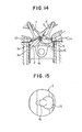
- a recess 15 which extends from a point below a spark plug 10 to another point below a free end portion of the fuel injection valve 14 is formed in the top wall of the piston 2 as shown in FIG. 14 and FIG. 15.
- the top wall of the piston is provided with a greater surface area owing to the existence of the recessed portion c. Further, it has also been found that the edge d of the peripheral edge of the opening becomes very hot over the entire periphery thereof, leading to a large heat loss and hence to an output loss.
- the recessed portion is formed in the shape of the angular edge portion on the outlet side of the vertical swirl. Separating action can therefore be assured for the vertical swirl, thereby making it possible to obtain stable stratified combustion by stratified combustion.
- the combustion chamber 27 is formed.
- an intake port 24 and an exhaust port 25 are connected in communication with the combustion chamber 27 via an intake opening 24A and an exhaust opening 25A, respectively.
- the controller performs the control so that at least in a low-load and low-rotation range, fuel is injected in a later stage of a compression stroke to form a reversed tumble flow of a rich air-fuel mixture around the spark plug but in a high-load range and in a high-rotation range, fuel is injected from an early stage of an intake stroke to form a uniform air-fuel mixture in the combustion chamber.
- the flow of inducted air therefore promotes the formation of the reversed tumble flow TF along the recessed portion 22A.
- an unillustrated ignition circuit is driven to initiate an ignition processing (shown by a ⁇ mark in FIG. 7) by the spark plug 30.
- an ignition processing shown by a ⁇ mark in FIG. 7
- injected fuel is ignited to burn so that the in-cylinder pressure of the combustion chamber 27 arises.
- the piston 22 is therefore pushed down to produce an output.
- the intake ports 24 extend in the vertical direction alongside the imaginary plane 40 on the one side of the cylinder head 21, the flow of inducted air flowing from the intake port 24 into the combustion chamber 27 is facilitated to downwardly flow in along the cylinder wall 23A on the side of the intake openings 24A and also to be introduced as a strong flow of inducted air directed to a lower part (toward the piston 22).
- the formation of a strong vertical swirl is therefore rendered easier.
- the corner portion of the peripheral edge of the recessed portion 22A is formed on the inlet side of the vertical swirl as a gently rounded portion M1 and on the outlet side of the vertical swirl as an edge portion M2 where the exhaust-side, tilted top wall behind the ridge of the pentroof-shaped raised portion 22B and the inner wall of the recessed portion 22A meet with each other. Accordingly, this modification exhibits similar effects as the first embodiment.
- the engine can therefore be operated stably even by lean burning of a stratified tumble flow composed of a rich air-fuel mixture and a superlean air-fuel mixture, thereby achieving an improvement in gas mileage. Further, when an air-fuel mixture richer than that used upon lean burning is caused to burn, a heat loss can also be reduced.
- the present invention can therefore significantly contribute to improvements in the efficiency and power output of an internal combustion engine.
Landscapes
- Engineering & Computer Science (AREA)
- Chemical & Material Sciences (AREA)
- Combustion & Propulsion (AREA)
- Mechanical Engineering (AREA)
- General Engineering & Computer Science (AREA)
- Combustion Methods Of Internal-Combustion Engines (AREA)
- Cylinder Crankcases Of Internal Combustion Engines (AREA)
Claims (15)
- Verbrennungsmotor mit Einspritzung in den Zylinder, versehen mit:einem Verbrennungsraum (27), der durch eine untere Zylinderkopfwand (21A) und eine obere Wand eines paßgenau in einen Zylinder eingesetzten Kolbens gebildet ist,einer Einlaßöffnung (24A), die in der unteren Zylinderkopfwand (21A) des Verbrennungsraums (27) so angeordnet ist, daß die Einlaßöffnung durch ein Einlaßventil geöffnet oder geschlossen werden kann,einer Auslaßöffnung (25A), die in der unteren Zylinderkopfwand (21A) des Verbrennungsraums (27) so angeordnet ist, daß die Auslaßöffnung durch ein Auslaßventil geöffnet oder geschlossen werden kann,einer Einlaßbohrung (24), die an ihrem unteren Ende durch die Einlaßöffnung mit dem Verbrennungsraum (27) in Verbindung steht, so daß in dem Verbrennungsraum (27) ein vertikaler Ansaugluftwirbel gebildet wird,einer Auslaßbohrung (25), die an ihrem unteren Ende durch die Auslaßöffnung mit dem Verbrennungsraum (27) in Verbindung steht, so daß Verbrennungsgas in dem Verbrennungsraum (27) abgeführt wird,einer Zündkerze (30), die auf der unteren Zylinderkopfwand (21A) des Verbrennungsraums (27) angeordnet ist, undeiner Kraftstoffeinspritzeinrichtung (H) zum direkten Einspritzen von Kraftstoff in den Verbrennungsraum (27), dadurch gekennzeichnet, daß:die Kraftstoffeinspritzeinrichtung (H) so angeordnet ist, daß der Kraftstoff in einen Kompressionshub eingespritzt wird, um eine geschichtete Verbrennung durchzuführen, wenn der Verbrennungsmotor unter geringer Last ist, oder in einen Ansaughub, um eine gleichförmige Verbrennung durchzuführen, wenn der Verbrennungsmotor unter großer Last ist;der Kolben (22) einen vertieften Teil (22A) aufweist, der in der oberen Wand des Kolbens (22) angeordnet ist, um die Bildung des vertikalen Wirbels mit durch die Einlaßöffnung in den Verbrennungsraum (27) zugeführter Ansaugluft zu fördern, undder vertiefte Teil (22A) an und entlang von einer Schnittlinie zwischen einer Innenwand des vertieften Teils (22A) und der oberen Wand des Kolbens (22) und auf einer Einlaßseite des vertikalen Wirbels einen Umfangsrand aufweist, wobei der Umfangsrand des vertieften Teils so zu einem Eckteil (M1) ausgebildet ist, so daß sich der Eckteil von der oberen Wand des Kolbens (22) aus in Richtung auf die Innenwand des vertieften Teils (22A) als schräges Teilstück neigt, über das die obere Wand des Kolbens und die Innenwand des vertieften Teils miteinander verbunden sind, wobei das schräge Teilstück in Form eines sanften gerundeten Teilstücks und/oder eines oder mehrerer linear geneigter Teilstücke vorliegt.
- Verbrennungsmotor mit Einspritzung in den Zylinder nach Anspruch 1, bei dem der Eckteil (M1) auf der Einlaßseite des vertikalen Wirbels so durch das schräge Teilstück gebildet wird, daß ein Flächeninhalt der oberen Wand des Kolbens (22) verkleinert wird.
- Verbrennungsmotor mit Einspritzung in den Zylinder nach Anspruch 1, bei dem das schräge Teilstück (M1) so ausgebildet ist, daß der einlaßseitige Umfangsrand des vertieften Teils an seinen in Richtung einer Achse einer Kurbelwelle des Verbrennungsmotors entgegengesetzten Endteilen in Richtung auf die Auslaßseite des vertikalen Wirbels verläuft.
- Verbrennungsmotor mit Einspritzung in den Zylinder nach einem vorangehenden Anspruch, bei dem das schräge Teilstück (M1) so ausgebildet ist, daß die Größe des schrägen Teilstücks von einem einlaßseitigen Mittelteil des Umfangsrandes des vertieften Teils in Richtung auf die entgegengesetzten Endteile allmählich kleiner wird.
- Verbrennungsmotor mit Einspritzung in den Zylinder nach Anspruch 1, bei dem der Umfangsrand des vertieften Teils auf der Auslaßseite des vertikalen Wirbels ausgebildet ist, so daß der von der oberen Wand des Kolbens (22) und einer Innenwand des vertieften Teils (22A) gebildete Eckteil in Form eines Kantenteils (M2) vorliegt.
- Verbrennungsmotor mit Einspritzung in den Zylinder nach Anspruch 5, bei dem der auslaßseitige Eckteil des vertieften Teils als winkliger Kantenteil (M2) ausgebildet ist.
- Verbrennungsmotor mit Einspritzung in den Zylinder nach Anspruch 5, bei dem der Umfangsrand des vertieften Teils auf der Auslaßseite des vertikalen Wirbels im Wesentlichen parallel zu einer gedachten Ebene (40) ausgebildet ist, in der eine Achse einer Kurbelwelle und eine Achse des Zylinders des Verbrennungsmotors enthalten sind.
- Verbrennungsmotor mit Einspritzung in den Zylinder nach Anspruch 1, bei dem das Einlaßventil auf einer Seite des Verbrennungsraums (27) angeordnet ist und der vertiefte Teil (22A) aus einer Mitte der oberen Wand des Kolbens (22) in Richtung auf die besagte eine Seite versetzt angeordnet ist, so daß der vertiefte Teil mindestens dem Einlaßventil zugewandt angeordnet ist.
- Verbrennungsmotor mit Einspritzung in den Zylinder nach Anspruch 8, bei dem der vertiefte Teil (22A) so ausgebildet ist, daß eine in Strömungsrichtung des vertikalen Wirbels genommene Querschnittsform in Form eines Kreisbogens vorliegt.
- Verbrennungsmotor mit Einspritzung in den Zylinder nach Anspruch 8, bei dem der vertiefte Teil (22A) in Form einer sphärischen Oberfläche ausgebildet ist.
- Verbrennungsmotor mit Einspritzung in den Zylinder nach Anspruch 1, bei dem die untere Zylinderkopfwand (21A) in Form eines Pultdachs ausgebildet ist, das aus einer einlaßventilseitigen geneigten unteren Wand, die auf der einen Seite ausgebildet ist, und einer auslaßventilseitigen geneigten unteren Wand, die auf der gegenüberliegenden Seite ausgebildet ist, besteht, und die obere Wand des Kolbens (22) in Form des Pultdachs ausgebildet ist, das eine einlaßventilseitige geneigte obere Wand und eine auslaßventilseitige geneigte obere Wand aufweist, die entsprechend der einlaßventilseitigen geneigten unteren Wand bzw. der auslaßventilseitigen geneigten unteren Wand ausgebildet sind.
- Verbrennungsmotor mit Einspritzung in den Zylinder nach Anspruch 11, bei dem der vertiefte Teil (22A) in der einlaßventilseitigen geneigten oberen Wand ausgebildet ist und der vertiefte Teil (22A) auf der Auslaßseite des vertikalen Wirbels auch höher ausgebildet ist als auf der Einlaßseite des vertikalen Wirbels.
- Verbrennungsmotor mit Einspritzung in den Zylinder nach Anspruch 11, bei dem der vertiefte Teil (22A) über die einlaßventilseitige geneigte obere Wand und die auslaßventilseitige geneigte obere Wand verlaufend ausgebildet ist.
- Verbrennungsmotor mit Einspritzung in den Zylinder nach Anspruch 13, bei dem der durch die auslaßventilseitige geneigte obere Wand und eine Innenwand des vertieften Teils (22A) gebildete Eckteil in Form eines Kantenteils (M2) als der Umfangsrand des vertieften Teils an der Auslaßseite des vertikalen Wirbels ausgebildet ist.
- Verbrennungsmotor mit Einspritzung in den Zylinder nach Anspruch 1, bei dem die Einlaßbohrung (24) auf einer Seite der gedachten Ebene (40) angeordnet ist und sich längsseits der gedachten Ebene (40) vertikal durch den Zylinderkopf (21) erstreckt.
Applications Claiming Priority (4)
| Application Number | Priority Date | Filing Date | Title |
|---|---|---|---|
| JP6981595 | 1995-03-28 | ||
| JP6981595 | 1995-03-28 | ||
| JP69815/95 | 1995-03-28 | ||
| PCT/JP1996/000802 WO1996030632A1 (en) | 1995-03-28 | 1996-03-27 | Cylinder injection type internal combustion engine |
Publications (3)
| Publication Number | Publication Date |
|---|---|
| EP0778402A1 EP0778402A1 (de) | 1997-06-11 |
| EP0778402A4 EP0778402A4 (de) | 1998-02-11 |
| EP0778402B1 true EP0778402B1 (de) | 2001-09-12 |
Family
ID=13413642
Family Applications (1)
| Application Number | Title | Priority Date | Filing Date |
|---|---|---|---|
| EP96907670A Expired - Lifetime EP0778402B1 (de) | 1995-03-28 | 1996-03-27 | Brennkraftmaschine des direkteinspritzung |
Country Status (7)
| Country | Link |
|---|---|
| US (1) | US5711269A (de) |
| EP (1) | EP0778402B1 (de) |
| JP (1) | JP3158443B2 (de) |
| KR (1) | KR100266059B1 (de) |
| CN (1) | CN1083527C (de) |
| DE (1) | DE69615130T2 (de) |
| WO (1) | WO1996030632A1 (de) |
Families Citing this family (52)
| Publication number | Priority date | Publication date | Assignee | Title |
|---|---|---|---|---|
| JP3746344B2 (ja) * | 1996-12-24 | 2006-02-15 | トヨタ自動車株式会社 | 内燃機関の燃焼室構造 |
| EP1739294A1 (de) | 1997-05-20 | 2007-01-03 | Nissan Motor Co., Ltd. | Kolben für eine direkteinspritzende Otto-Brennkraftmaschine |
| FR2763646B1 (fr) * | 1997-05-20 | 1999-07-02 | Renault | Moteur a injection directe et allumage commande |
| FR2763995B1 (fr) * | 1997-05-29 | 1999-07-02 | Renault | Moteur a injection directe et allumage commande |
| AT2333U1 (de) * | 1997-08-11 | 1998-08-25 | Avl List Gmbh | Brennkraftmaschine mit fremdzündung |
| FR2770875B1 (fr) * | 1997-11-13 | 1999-12-24 | Renault | Moteur a combustion interne a allumage commande, a injection directe et a bougie decalee |
| JPH11148355A (ja) * | 1997-11-14 | 1999-06-02 | Mazda Motor Corp | 筒内噴射型火花点火式エンジン |
| FR2772073B1 (fr) * | 1997-12-08 | 2000-02-04 | Renault | Moteur a combustion interne a allumage commande et a injection directe |
| FR2772074B1 (fr) * | 1997-12-08 | 2000-02-04 | Renault | Moteur a combustion interne a allumage commande et a injection directe |
| JP3692749B2 (ja) * | 1997-12-22 | 2005-09-07 | 日産自動車株式会社 | 筒内噴射式内燃機関のピストン |
| JP3644228B2 (ja) * | 1998-01-07 | 2005-04-27 | 日産自動車株式会社 | 筒内噴射式火花点火機関 |
| DE19801607A1 (de) * | 1998-01-17 | 1999-07-22 | Audi Ag | Brennkraftmaschine und Verfahren zur Gemischaufbereitung bei einer Brennkraftmaschine |
| DE19809066A1 (de) * | 1998-03-04 | 1999-09-09 | Audi Ag | Direkteinspritzende Brennkraftmaschine |
| KR20010074482A (ko) * | 1998-04-10 | 2001-08-04 | 추후제출 | 점화 제어 방식의 직접 분사형 내연 기관 |
| SE519775C2 (sv) * | 1998-05-14 | 2003-04-08 | Volvo Car Corp | Förbränningsmotor |
| FR2778694B1 (fr) * | 1998-05-18 | 2001-01-19 | Renault | Moteur a combustion interne a allumage commande et a injection directe |
| DE19826865B4 (de) * | 1998-06-17 | 2005-04-14 | Audi Ag | Direkteinspritzende Brennkraftmaschine |
| DE19827463A1 (de) * | 1998-06-19 | 1999-12-23 | Fev Motorentech Gmbh | Direkteinspritzender Dieselmotor mit tumblegestütztem Brennverfahren |
| DE19835563A1 (de) * | 1998-08-06 | 2000-02-10 | Volkswagen Ag | Viertakt-Brennkraftmaschine mit Direkteinspritzung |
| FR2783566B1 (fr) * | 1998-09-23 | 2000-10-27 | Renault | Moteur a combustion interne a allumage commande |
| FR2784714B1 (fr) * | 1998-10-16 | 2005-07-15 | Renault | Procede de commande d'un moteur injection directe essence equipe d'un alternateur demarreur integre au volant d'inertie |
| DE59806643D1 (de) * | 1998-11-23 | 2003-01-23 | Ford Global Tech Inc | Otto-Brennkraftmaschine mit direkter Kraftstoffeinspritzung |
| JP3537347B2 (ja) * | 1999-04-02 | 2004-06-14 | トヨタ自動車株式会社 | 筒内噴射式火花点火内燃機関 |
| JP3370947B2 (ja) * | 1999-04-09 | 2003-01-27 | トヨタ自動車株式会社 | 筒内噴射式火花点火内燃機関 |
| JP3598880B2 (ja) * | 1999-06-07 | 2004-12-08 | 日産自動車株式会社 | 直噴火花点火式内燃機関 |
| JP3692860B2 (ja) * | 1999-09-28 | 2005-09-07 | 日産自動車株式会社 | 筒内噴射式火花点火機関 |
| US6269790B1 (en) | 1999-11-05 | 2001-08-07 | Ford Global Technologies, Inc. | Combustion chamber for DISI engines with exhaust side piston bowl |
| US6286477B1 (en) | 1999-12-21 | 2001-09-11 | Ford Global Technologies, Inc. | Combustion chamber for direct-injected spark-ignited engines with swirl airflows |
| US6267096B1 (en) | 2000-01-07 | 2001-07-31 | Ford Global Technologies, Inc. | Three-valve cylinder head system |
| JP2001248447A (ja) * | 2000-03-06 | 2001-09-14 | Yamaha Motor Co Ltd | 筒内燃料噴射式エンジンにおける燃焼室構造 |
| JP2002327622A (ja) * | 2001-04-27 | 2002-11-15 | Unisia Jecs Corp | 内燃機関のピストン |
| US6588396B1 (en) * | 2002-02-01 | 2003-07-08 | General Motors Corporation | Spark ignition direct injection engine with oval fuel spray into oblong piston bowl |
| US6745745B2 (en) | 2002-02-22 | 2004-06-08 | General Motors Corporation | Combustion chamber for reverse tumble spark ignition direct injection engine |
| JP4172496B2 (ja) * | 2006-05-11 | 2008-10-29 | トヨタ自動車株式会社 | 可変圧縮比内燃機関 |
| CN101144413B (zh) * | 2007-09-28 | 2010-06-02 | 清华大学 | 一种缸内直喷汽油机燃烧室 |
| US9512779B2 (en) * | 2010-04-27 | 2016-12-06 | Achates Power, Inc. | Swirl-conserving combustion chamber construction for opposed-piston engines |
| US10180115B2 (en) * | 2010-04-27 | 2019-01-15 | Achates Power, Inc. | Piston crown bowls defining combustion chamber constructions in opposed-piston engines |
| JP5782109B2 (ja) * | 2010-04-27 | 2015-09-24 | アカーテース パワー,インク. | 対向ピストン式エンジン用の燃焼室構造 |
| JP5661779B2 (ja) * | 2010-09-03 | 2015-01-28 | 本田技研工業株式会社 | 内燃機関診断装置及び内燃機関診断方法 |
| CN105019999B (zh) * | 2014-04-30 | 2017-09-29 | 上海汽车集团股份有限公司 | 汽油机燃烧系统及汽油机燃油喷射方法 |
| WO2017052207A1 (ko) * | 2015-09-22 | 2017-03-30 | 조주혁 | 기관부 외부의 공기 압축 기구에 의한 급기 방식의 2 행정 1 사이클 내연기관 |
| US10060387B2 (en) * | 2016-06-22 | 2018-08-28 | Ford Global Technologies, Llc | Multi-step combustion chamber with multi-step cylinder head |
| CN106593681A (zh) * | 2016-12-20 | 2017-04-26 | 中国第汽车股份有限公司 | 一种用于1l直喷汽油机的半球形燃烧室 |
| CN106640338B (zh) * | 2016-12-28 | 2019-03-08 | 天津大学 | 一种顶置气门二冲程缸内直喷汽油机燃烧室 |
| JP6566000B2 (ja) * | 2017-06-02 | 2019-08-28 | マツダ株式会社 | エンジン |
| EP3617470A4 (de) | 2017-06-02 | 2020-03-04 | Mazda Motor Corporation | Brennkammerstruktur für motoren |
| JP6565999B2 (ja) * | 2017-06-02 | 2019-08-28 | マツダ株式会社 | エンジン |
| WO2018221638A1 (ja) | 2017-06-02 | 2018-12-06 | マツダ株式会社 | エンジンの燃焼室構造 |
| FR3071879B1 (fr) * | 2017-09-29 | 2022-03-11 | Ifp Energies Now | Moteur a combustion interne a deux soupapes |
| JP2020002844A (ja) * | 2018-06-27 | 2020-01-09 | トヨタ自動車株式会社 | 内燃機関の制御システム |
| EP4293209A4 (de) * | 2021-05-08 | 2024-04-24 | Zhejiang Geely Holding Group Co., Ltd. | Verbrennungssystem für ein fahrzeug und fahrzeug |
| CN115597052B (zh) * | 2022-09-30 | 2025-10-03 | 北京天地融创科技股份有限公司 | 一种适应于四角切圆锅炉灵活调峰的燃烧系统和方法 |
Family Cites Families (26)
| Publication number | Priority date | Publication date | Assignee | Title |
|---|---|---|---|---|
| FR2359971A1 (fr) * | 1976-07-28 | 1978-02-24 | Citroen Sa | Moteur a combustion interne |
| JPS55180028U (de) * | 1979-06-12 | 1980-12-24 | ||
| JPS5934417A (ja) * | 1982-08-19 | 1984-02-24 | Kawasaki Heavy Ind Ltd | 2サイクルエンジン |
| JPS5939921A (ja) * | 1982-08-27 | 1984-03-05 | Toyota Central Res & Dev Lab Inc | 圧縮着火式直接噴射内燃機関 |
| US4693218A (en) * | 1984-09-12 | 1987-09-15 | Yanmar Diesel Engine Co., Ltd. | Internal combustion engine |
| JPS61202631A (ja) * | 1985-03-06 | 1986-09-08 | ヤンマー農機株式会社 | ロ−ルベ−ラの結束装置 |
| JPS61202631U (de) * | 1985-06-07 | 1986-12-19 | ||
| JPS6227247A (ja) * | 1985-07-26 | 1987-02-05 | Ricoh Co Ltd | 記録装置の給紙制御装置 |
| JPS6227222A (ja) * | 1985-07-29 | 1987-02-05 | Fuji Heavy Ind Ltd | 部品パレツト交換装置 |
| JPS6267222A (ja) * | 1985-09-18 | 1987-03-26 | Mazda Motor Corp | エンジンの燃焼室 |
| JPH06100089B2 (ja) * | 1986-02-01 | 1994-12-12 | マツダ株式会社 | 内燃機関の燃焼室 |
| JP2572728B2 (ja) * | 1986-02-01 | 1997-01-16 | マツダ株式会社 | 内燃機関の燃焼室 |
| JPH07105657B2 (ja) * | 1989-07-19 | 1995-11-13 | 三菱電機株式会社 | 電子走査アンテナ |
| JPH04166612A (ja) * | 1990-10-31 | 1992-06-12 | Toyota Motor Corp | 筒内噴射式内燃機関 |
| JPH04124426A (ja) * | 1990-09-14 | 1992-04-24 | Mazda Motor Corp | エンジンの燃焼室構造 |
| JPH04224231A (ja) * | 1990-12-26 | 1992-08-13 | Toyota Motor Corp | 筒内噴射式内燃機関 |
| US5115774A (en) * | 1990-12-26 | 1992-05-26 | Toyota Jidosha Kabushiki Kaisha | Internal combustion engine |
| JPH0526047A (ja) * | 1991-07-19 | 1993-02-02 | Toyota Motor Corp | 筒内噴射式2サイクル内燃機関 |
| JPH0579337A (ja) * | 1991-09-19 | 1993-03-30 | Toyota Motor Corp | 筒内噴射式内燃機関 |
| JPH05179957A (ja) * | 1991-12-26 | 1993-07-20 | Toyota Motor Corp | 2サイクル内燃機関 |
| JP2792308B2 (ja) * | 1992-02-28 | 1998-09-03 | 三菱自動車工業株式会社 | 筒内噴射型内燃機関 |
| JP2946917B2 (ja) * | 1992-02-28 | 1999-09-13 | 三菱自動車工業株式会社 | 内燃機関 |
| JPH05240045A (ja) * | 1992-02-28 | 1993-09-17 | Mitsubishi Motors Corp | 渦流生成型内燃機関 |
| US5305720A (en) * | 1992-02-28 | 1994-04-26 | Mitsubishi Jidosha Kogyo Kabushiki Kaisha | Internal combustion engine |
| JP2917713B2 (ja) * | 1992-11-04 | 1999-07-12 | 三菱自動車工業株式会社 | 筒内噴射型内燃機関 |
| US5327864A (en) * | 1993-03-08 | 1994-07-12 | Chrysler Corporation | Stratified-charge internal combustion engine with fuel injection and dual ignition |
-
1996
- 1996-03-27 KR KR1019960706677A patent/KR100266059B1/ko not_active Expired - Fee Related
- 1996-03-27 WO PCT/JP1996/000802 patent/WO1996030632A1/ja not_active Ceased
- 1996-03-27 DE DE69615130T patent/DE69615130T2/de not_active Expired - Fee Related
- 1996-03-27 JP JP52557296A patent/JP3158443B2/ja not_active Expired - Fee Related
- 1996-03-27 CN CN96190255A patent/CN1083527C/zh not_active Expired - Fee Related
- 1996-03-27 EP EP96907670A patent/EP0778402B1/de not_active Expired - Lifetime
- 1996-03-27 US US08/750,161 patent/US5711269A/en not_active Expired - Lifetime
Also Published As
| Publication number | Publication date |
|---|---|
| DE69615130T2 (de) | 2002-06-13 |
| CN1149904A (zh) | 1997-05-14 |
| KR970703481A (ko) | 1997-07-03 |
| EP0778402A1 (de) | 1997-06-11 |
| EP0778402A4 (de) | 1998-02-11 |
| US5711269A (en) | 1998-01-27 |
| WO1996030632A1 (en) | 1996-10-03 |
| KR100266059B1 (ko) | 2000-10-02 |
| DE69615130D1 (de) | 2001-10-18 |
| JP3158443B2 (ja) | 2001-04-23 |
| CN1083527C (zh) | 2002-04-24 |
Similar Documents
| Publication | Publication Date | Title |
|---|---|---|
| EP0778402B1 (de) | Brennkraftmaschine des direkteinspritzung | |
| US5305720A (en) | Internal combustion engine | |
| US5927244A (en) | Combustion chamber structure having piston cavity | |
| JPWO1996030632A1 (ja) | 筒内噴射型内燃機関 | |
| US6173690B1 (en) | In-cylinder direct-injection spark-ignition engine | |
| US5806482A (en) | In-cylinder injection internal combustion engine | |
| US20210040913A1 (en) | Method for operating a spark-ignition internal combustion engine | |
| AU702939B2 (en) | In-cylinder injection internal combustion engine | |
| US6612282B2 (en) | Combustion chamber for DISI engine | |
| US4770139A (en) | Engine combustion chamber structure | |
| US5890466A (en) | Device for injecting fuel at the exhaust port of an engine cylinder | |
| US4178903A (en) | Internal combustion engine with an auxiliary combustion chamber | |
| JP2653226B2 (ja) | 2ストロークディーゼルエンジン | |
| JP2917713B2 (ja) | 筒内噴射型内燃機関 | |
| JP3591141B2 (ja) | 筒内直接噴射式火花点火内燃機関 | |
| JPH05240045A (ja) | 渦流生成型内燃機関 | |
| JPH06147022A (ja) | 筒内噴射型内燃機関 | |
| JP2936798B2 (ja) | 筒内噴射式内燃機関 | |
| JP3300965B2 (ja) | 2サイクル筒内噴射エンジン | |
| JPH10220230A (ja) | 筒内噴射型内燃機関 | |
| JPH0533650A (ja) | 2サイクル内燃機関 | |
| GB2287985A (en) | Multi-cylinder two-stroke engine charge intake system | |
| JPS63129116A (ja) | 相流層状給気方式内燃機関 | |
| JPS62131916A (ja) | 火花点火式2サイクルエンジン | |
| JPH02305319A (ja) | エンジンの燃焼室構造 |
Legal Events
| Date | Code | Title | Description |
|---|---|---|---|
| PUAI | Public reference made under article 153(3) epc to a published international application that has entered the european phase |
Free format text: ORIGINAL CODE: 0009012 |
|
| 17P | Request for examination filed |
Effective date: 19970127 |
|
| AK | Designated contracting states |
Kind code of ref document: A1 Designated state(s): DE FR GB |
|
| A4 | Supplementary search report drawn up and despatched | ||
| AK | Designated contracting states |
Kind code of ref document: A4 Designated state(s): DE FR GB |
|
| 17Q | First examination report despatched |
Effective date: 19980525 |
|
| GRAG | Despatch of communication of intention to grant |
Free format text: ORIGINAL CODE: EPIDOS AGRA |
|
| GRAG | Despatch of communication of intention to grant |
Free format text: ORIGINAL CODE: EPIDOS AGRA |
|
| GRAH | Despatch of communication of intention to grant a patent |
Free format text: ORIGINAL CODE: EPIDOS IGRA |
|
| GRAH | Despatch of communication of intention to grant a patent |
Free format text: ORIGINAL CODE: EPIDOS IGRA |
|
| GRAA | (expected) grant |
Free format text: ORIGINAL CODE: 0009210 |
|
| AK | Designated contracting states |
Kind code of ref document: B1 Designated state(s): DE FR GB |
|
| REF | Corresponds to: |
Ref document number: 69615130 Country of ref document: DE Date of ref document: 20011018 |
|
| ET | Fr: translation filed | ||
| REG | Reference to a national code |
Ref country code: GB Ref legal event code: IF02 |
|
| PLBE | No opposition filed within time limit |
Free format text: ORIGINAL CODE: 0009261 |
|
| STAA | Information on the status of an ep patent application or granted ep patent |
Free format text: STATUS: NO OPPOSITION FILED WITHIN TIME LIMIT |
|
| 26N | No opposition filed | ||
| REG | Reference to a national code |
Ref country code: FR Ref legal event code: CA |
|
| PGFP | Annual fee paid to national office [announced via postgrant information from national office to epo] |
Ref country code: FR Payment date: 20060308 Year of fee payment: 11 |
|
| PGFP | Annual fee paid to national office [announced via postgrant information from national office to epo] |
Ref country code: DE Payment date: 20060323 Year of fee payment: 11 |
|
| GBPC | Gb: european patent ceased through non-payment of renewal fee |
Effective date: 20070327 |
|
| REG | Reference to a national code |
Ref country code: FR Ref legal event code: ST Effective date: 20071130 |
|
| PG25 | Lapsed in a contracting state [announced via postgrant information from national office to epo] |
Ref country code: DE Free format text: LAPSE BECAUSE OF NON-PAYMENT OF DUE FEES Effective date: 20071002 |
|
| PG25 | Lapsed in a contracting state [announced via postgrant information from national office to epo] |
Ref country code: GB Free format text: LAPSE BECAUSE OF NON-PAYMENT OF DUE FEES Effective date: 20070327 |
|
| PG25 | Lapsed in a contracting state [announced via postgrant information from national office to epo] |
Ref country code: FR Free format text: LAPSE BECAUSE OF NON-PAYMENT OF DUE FEES Effective date: 20070402 |
|
| PGFP | Annual fee paid to national office [announced via postgrant information from national office to epo] |
Ref country code: GB Payment date: 20060322 Year of fee payment: 11 |