EP0779089A2 - Verfahren und Vorrichtung zum Abtrennen von Öl aus Abwasser, das emulgiertes Öl enthält - Google Patents
Verfahren und Vorrichtung zum Abtrennen von Öl aus Abwasser, das emulgiertes Öl enthält Download PDFInfo
- Publication number
- EP0779089A2 EP0779089A2 EP96120209A EP96120209A EP0779089A2 EP 0779089 A2 EP0779089 A2 EP 0779089A2 EP 96120209 A EP96120209 A EP 96120209A EP 96120209 A EP96120209 A EP 96120209A EP 0779089 A2 EP0779089 A2 EP 0779089A2
- Authority
- EP
- European Patent Office
- Prior art keywords
- oil
- anode
- compartment
- water separation
- diaphragm
- Prior art date
- Legal status (The legal status is an assumption and is not a legal conclusion. Google has not performed a legal analysis and makes no representation as to the accuracy of the status listed.)
- Withdrawn
Links
- XLYOFNOQVPJJNP-UHFFFAOYSA-N water Substances O XLYOFNOQVPJJNP-UHFFFAOYSA-N 0.000 title claims abstract description 267
- 239000002351 wastewater Substances 0.000 title claims abstract description 132
- 238000000034 method Methods 0.000 title claims abstract description 46
- 238000000926 separation method Methods 0.000 claims abstract description 242
- 239000004094 surface-active agent Substances 0.000 claims abstract description 56
- 239000007788 liquid Substances 0.000 claims abstract description 41
- 239000000463 material Substances 0.000 claims abstract description 39
- 238000005868 electrolysis reaction Methods 0.000 claims abstract description 33
- 230000009471 action Effects 0.000 claims abstract description 15
- 238000007599 discharging Methods 0.000 claims abstract 8
- 238000004140 cleaning Methods 0.000 claims description 184
- 239000002736 nonionic surfactant Substances 0.000 claims description 50
- 239000000356 contaminant Substances 0.000 claims description 17
- PMZURENOXWZQFD-UHFFFAOYSA-L Sodium Sulfate Chemical group [Na+].[Na+].[O-]S([O-])(=O)=O PMZURENOXWZQFD-UHFFFAOYSA-L 0.000 claims description 11
- 229910052938 sodium sulfate Inorganic materials 0.000 claims description 11
- 235000011152 sodium sulphate Nutrition 0.000 claims description 11
- 238000010438 heat treatment Methods 0.000 claims description 6
- 239000001488 sodium phosphate Substances 0.000 claims description 3
- 229910000162 sodium phosphate Inorganic materials 0.000 claims description 3
- RYFMWSXOAZQYPI-UHFFFAOYSA-K trisodium phosphate Chemical compound [Na+].[Na+].[Na+].[O-]P([O-])([O-])=O RYFMWSXOAZQYPI-UHFFFAOYSA-K 0.000 claims description 3
- 238000006386 neutralization reaction Methods 0.000 claims 1
- 230000003472 neutralizing effect Effects 0.000 claims 1
- 239000003921 oil Substances 0.000 description 169
- 239000000243 solution Substances 0.000 description 116
- -1 glycol ethers Chemical class 0.000 description 44
- 239000003945 anionic surfactant Substances 0.000 description 30
- 239000003599 detergent Substances 0.000 description 30
- 238000012360 testing method Methods 0.000 description 30
- 125000000129 anionic group Chemical group 0.000 description 22
- 239000010730 cutting oil Substances 0.000 description 22
- 230000000694 effects Effects 0.000 description 20
- 230000000052 comparative effect Effects 0.000 description 19
- 230000001965 increasing effect Effects 0.000 description 19
- 239000002585 base Substances 0.000 description 18
- 239000011734 sodium Substances 0.000 description 18
- 229910052708 sodium Inorganic materials 0.000 description 18
- 230000002378 acidificating effect Effects 0.000 description 15
- 239000012528 membrane Substances 0.000 description 14
- 238000011282 treatment Methods 0.000 description 14
- JEIPFZHSYJVQDO-UHFFFAOYSA-N iron(III) oxide Inorganic materials O=[Fe]O[Fe]=O JEIPFZHSYJVQDO-UHFFFAOYSA-N 0.000 description 13
- 239000010808 liquid waste Substances 0.000 description 12
- 238000005188 flotation Methods 0.000 description 11
- 239000012466 permeate Substances 0.000 description 11
- 239000002245 particle Substances 0.000 description 10
- 229920003171 Poly (ethylene oxide) Polymers 0.000 description 9
- 238000001471 micro-filtration Methods 0.000 description 9
- 230000008901 benefit Effects 0.000 description 8
- 239000002826 coolant Substances 0.000 description 8
- 239000000839 emulsion Substances 0.000 description 8
- 239000001257 hydrogen Substances 0.000 description 8
- 229910052739 hydrogen Inorganic materials 0.000 description 8
- 230000003449 preventive effect Effects 0.000 description 8
- 125000005037 alkyl phenyl group Chemical group 0.000 description 7
- 238000013461 design Methods 0.000 description 7
- RTZKZFJDLAIYFH-UHFFFAOYSA-N ether Substances CCOCC RTZKZFJDLAIYFH-UHFFFAOYSA-N 0.000 description 7
- HEMHJVSKTPXQMS-UHFFFAOYSA-M Sodium hydroxide Chemical compound [OH-].[Na+] HEMHJVSKTPXQMS-UHFFFAOYSA-M 0.000 description 6
- 238000006243 chemical reaction Methods 0.000 description 6
- 238000005516 engineering process Methods 0.000 description 6
- 238000007667 floating Methods 0.000 description 6
- 239000011148 porous material Substances 0.000 description 6
- 239000000126 substance Substances 0.000 description 6
- 239000002253 acid Substances 0.000 description 5
- 239000013543 active substance Substances 0.000 description 5
- 239000008346 aqueous phase Substances 0.000 description 5
- 239000007864 aqueous solution Substances 0.000 description 5
- 230000001186 cumulative effect Effects 0.000 description 5
- GPRLSGONYQIRFK-UHFFFAOYSA-N hydron Chemical compound [H+] GPRLSGONYQIRFK-UHFFFAOYSA-N 0.000 description 5
- 229910052751 metal Inorganic materials 0.000 description 5
- 239000002184 metal Substances 0.000 description 5
- 230000036962 time dependent Effects 0.000 description 5
- 239000010936 titanium Substances 0.000 description 5
- OYPRJOBELJOOCE-UHFFFAOYSA-N Calcium Chemical compound [Ca] OYPRJOBELJOOCE-UHFFFAOYSA-N 0.000 description 4
- QVGXLLKOCUKJST-UHFFFAOYSA-N atomic oxygen Chemical compound [O] QVGXLLKOCUKJST-UHFFFAOYSA-N 0.000 description 4
- 229910052791 calcium Inorganic materials 0.000 description 4
- 239000011575 calcium Substances 0.000 description 4
- 238000011109 contamination Methods 0.000 description 4
- 235000014113 dietary fatty acids Nutrition 0.000 description 4
- 239000000194 fatty acid Substances 0.000 description 4
- 229930195729 fatty acid Natural products 0.000 description 4
- 239000003112 inhibitor Substances 0.000 description 4
- 239000000203 mixture Substances 0.000 description 4
- 239000001301 oxygen Substances 0.000 description 4
- 229910052760 oxygen Inorganic materials 0.000 description 4
- BASFCYQUMIYNBI-UHFFFAOYSA-N platinum Chemical compound [Pt] BASFCYQUMIYNBI-UHFFFAOYSA-N 0.000 description 4
- 235000019832 sodium triphosphate Nutrition 0.000 description 4
- 229920001059 synthetic polymer Polymers 0.000 description 4
- 239000004743 Polypropylene Substances 0.000 description 3
- 239000003513 alkali Substances 0.000 description 3
- 229940045714 alkyl sulfonate alkylating agent Drugs 0.000 description 3
- 238000004458 analytical method Methods 0.000 description 3
- 229910052788 barium Inorganic materials 0.000 description 3
- 230000008859 change Effects 0.000 description 3
- 239000000835 fiber Substances 0.000 description 3
- 229920001983 poloxamer Polymers 0.000 description 3
- 229920001155 polypropylene Polymers 0.000 description 3
- 230000002829 reductive effect Effects 0.000 description 3
- 239000011347 resin Substances 0.000 description 3
- 229920005989 resin Polymers 0.000 description 3
- BDHFUVZGWQCTTF-UHFFFAOYSA-M sulfonate Chemical compound [O-]S(=O)=O BDHFUVZGWQCTTF-UHFFFAOYSA-M 0.000 description 3
- UOCLXMDMGBRAIB-UHFFFAOYSA-N 1,1,1-trichloroethane Chemical compound CC(Cl)(Cl)Cl UOCLXMDMGBRAIB-UHFFFAOYSA-N 0.000 description 2
- 241000226585 Antennaria plantaginifolia Species 0.000 description 2
- DGAQECJNVWCQMB-PUAWFVPOSA-M Ilexoside XXIX Chemical compound C[C@@H]1CC[C@@]2(CC[C@@]3(C(=CC[C@H]4[C@]3(CC[C@@H]5[C@@]4(CC[C@@H](C5(C)C)OS(=O)(=O)[O-])C)C)[C@@H]2[C@]1(C)O)C)C(=O)O[C@H]6[C@@H]([C@H]([C@@H]([C@H](O6)CO)O)O)O.[Na+] DGAQECJNVWCQMB-PUAWFVPOSA-M 0.000 description 2
- 239000002202 Polyethylene glycol Substances 0.000 description 2
- 229920001214 Polysorbate 60 Polymers 0.000 description 2
- RTAQQCXQSZGOHL-UHFFFAOYSA-N Titanium Chemical compound [Ti] RTAQQCXQSZGOHL-UHFFFAOYSA-N 0.000 description 2
- 229910052784 alkaline earth metal Inorganic materials 0.000 description 2
- 150000001342 alkaline earth metals Chemical class 0.000 description 2
- 150000005215 alkyl ethers Chemical class 0.000 description 2
- 150000001768 cations Chemical class 0.000 description 2
- 238000007796 conventional method Methods 0.000 description 2
- 230000002939 deleterious effect Effects 0.000 description 2
- 238000011161 development Methods 0.000 description 2
- 230000002708 enhancing effect Effects 0.000 description 2
- 238000001914 filtration Methods 0.000 description 2
- 230000002209 hydrophobic effect Effects 0.000 description 2
- 230000006872 improvement Effects 0.000 description 2
- 230000007246 mechanism Effects 0.000 description 2
- 239000000693 micelle Substances 0.000 description 2
- 239000005416 organic matter Substances 0.000 description 2
- 239000003960 organic solvent Substances 0.000 description 2
- 229910052697 platinum Inorganic materials 0.000 description 2
- 229920001223 polyethylene glycol Polymers 0.000 description 2
- 239000002244 precipitate Substances 0.000 description 2
- 230000002035 prolonged effect Effects 0.000 description 2
- 238000005096 rolling process Methods 0.000 description 2
- 229910052719 titanium Inorganic materials 0.000 description 2
- 238000000108 ultra-filtration Methods 0.000 description 2
- 239000005995 Aluminium silicate Substances 0.000 description 1
- OKTJSMMVPCPJKN-UHFFFAOYSA-N Carbon Chemical compound [C] OKTJSMMVPCPJKN-UHFFFAOYSA-N 0.000 description 1
- UFHFLCQGNIYNRP-UHFFFAOYSA-N Hydrogen Chemical compound [H][H] UFHFLCQGNIYNRP-UHFFFAOYSA-N 0.000 description 1
- FYYHWMGAXLPEAU-UHFFFAOYSA-N Magnesium Chemical compound [Mg] FYYHWMGAXLPEAU-UHFFFAOYSA-N 0.000 description 1
- CBENFWSGALASAD-UHFFFAOYSA-N Ozone Chemical compound [O-][O+]=O CBENFWSGALASAD-UHFFFAOYSA-N 0.000 description 1
- 239000006004 Quartz sand Substances 0.000 description 1
- VYPSYNLAJGMNEJ-UHFFFAOYSA-N Silicium dioxide Chemical compound O=[Si]=O VYPSYNLAJGMNEJ-UHFFFAOYSA-N 0.000 description 1
- 239000004115 Sodium Silicate Substances 0.000 description 1
- 229910021536 Zeolite Inorganic materials 0.000 description 1
- 150000007513 acids Chemical class 0.000 description 1
- 230000002411 adverse Effects 0.000 description 1
- 150000001298 alcohols Chemical class 0.000 description 1
- 235000012211 aluminium silicate Nutrition 0.000 description 1
- 230000003254 anti-foaming effect Effects 0.000 description 1
- 239000002518 antifoaming agent Substances 0.000 description 1
- DSAJWYNOEDNPEQ-UHFFFAOYSA-N barium atom Chemical compound [Ba] DSAJWYNOEDNPEQ-UHFFFAOYSA-N 0.000 description 1
- 229910021538 borax Inorganic materials 0.000 description 1
- 230000003139 buffering effect Effects 0.000 description 1
- 239000006227 byproduct Substances 0.000 description 1
- 229910052799 carbon Inorganic materials 0.000 description 1
- 230000003247 decreasing effect Effects 0.000 description 1
- 230000000779 depleting effect Effects 0.000 description 1
- 230000008021 deposition Effects 0.000 description 1
- 238000010790 dilution Methods 0.000 description 1
- 239000012895 dilution Substances 0.000 description 1
- HNPSIPDUKPIQMN-UHFFFAOYSA-N dioxosilane;oxo(oxoalumanyloxy)alumane Chemical compound O=[Si]=O.O=[Al]O[Al]=O HNPSIPDUKPIQMN-UHFFFAOYSA-N 0.000 description 1
- 238000010494 dissociation reaction Methods 0.000 description 1
- 230000005593 dissociations Effects 0.000 description 1
- 238000004945 emulsification Methods 0.000 description 1
- LYCAIKOWRPUZTN-UHFFFAOYSA-N ethylene glycol Natural products OCCO LYCAIKOWRPUZTN-UHFFFAOYSA-N 0.000 description 1
- 230000004907 flux Effects 0.000 description 1
- XLYOFNOQVPJJNP-UHFFFAOYSA-M hydroxide Chemical compound [OH-] XLYOFNOQVPJJNP-UHFFFAOYSA-M 0.000 description 1
- 150000004679 hydroxides Chemical class 0.000 description 1
- WGCNASOHLSPBMP-UHFFFAOYSA-N hydroxyacetaldehyde Natural products OCC=O WGCNASOHLSPBMP-UHFFFAOYSA-N 0.000 description 1
- 230000002401 inhibitory effect Effects 0.000 description 1
- 238000002347 injection Methods 0.000 description 1
- 239000007924 injection Substances 0.000 description 1
- 230000003993 interaction Effects 0.000 description 1
- 239000002563 ionic surfactant Substances 0.000 description 1
- NLYAJNPCOHFWQQ-UHFFFAOYSA-N kaolin Chemical compound O.O.O=[Al]O[Si](=O)O[Si](=O)O[Al]=O NLYAJNPCOHFWQQ-UHFFFAOYSA-N 0.000 description 1
- 230000000670 limiting effect Effects 0.000 description 1
- 238000003754 machining Methods 0.000 description 1
- 229910052749 magnesium Inorganic materials 0.000 description 1
- 239000011777 magnesium Substances 0.000 description 1
- 238000004519 manufacturing process Methods 0.000 description 1
- 239000002480 mineral oil Substances 0.000 description 1
- 235000010446 mineral oil Nutrition 0.000 description 1
- 239000011490 mineral wool Substances 0.000 description 1
- 238000010979 pH adjustment Methods 0.000 description 1
- 238000012856 packing Methods 0.000 description 1
- 239000013618 particulate matter Substances 0.000 description 1
- 229920000915 polyvinyl chloride Polymers 0.000 description 1
- 239000004800 polyvinyl chloride Substances 0.000 description 1
- OTYBMLCTZGSZBG-UHFFFAOYSA-L potassium sulfate Chemical compound [K+].[K+].[O-]S([O-])(=O)=O OTYBMLCTZGSZBG-UHFFFAOYSA-L 0.000 description 1
- 229910052939 potassium sulfate Inorganic materials 0.000 description 1
- 235000011151 potassium sulphates Nutrition 0.000 description 1
- 238000011045 prefiltration Methods 0.000 description 1
- 230000001737 promoting effect Effects 0.000 description 1
- 230000001105 regulatory effect Effects 0.000 description 1
- 238000009877 rendering Methods 0.000 description 1
- 150000003839 salts Chemical class 0.000 description 1
- 238000004904 shortening Methods 0.000 description 1
- NTHWMYGWWRZVTN-UHFFFAOYSA-N sodium silicate Chemical compound [Na+].[Na+].[O-][Si]([O-])=O NTHWMYGWWRZVTN-UHFFFAOYSA-N 0.000 description 1
- 229910052911 sodium silicate Inorganic materials 0.000 description 1
- 235000010339 sodium tetraborate Nutrition 0.000 description 1
- 239000002904 solvent Substances 0.000 description 1
- 229910001220 stainless steel Inorganic materials 0.000 description 1
- 239000003206 sterilizing agent Substances 0.000 description 1
- 239000000758 substrate Substances 0.000 description 1
- 229920002994 synthetic fiber Polymers 0.000 description 1
- 239000012209 synthetic fiber Substances 0.000 description 1
- 238000012956 testing procedure Methods 0.000 description 1
- BSVBQGMMJUBVOD-UHFFFAOYSA-N trisodium borate Chemical compound [Na+].[Na+].[Na+].[O-]B([O-])[O-] BSVBQGMMJUBVOD-UHFFFAOYSA-N 0.000 description 1
- 239000002699 waste material Substances 0.000 description 1
- 238000004065 wastewater treatment Methods 0.000 description 1
- 239000010457 zeolite Substances 0.000 description 1
- 229910000859 α-Fe Inorganic materials 0.000 description 1
Images


Classifications
-
- C—CHEMISTRY; METALLURGY
- C02—TREATMENT OF WATER, WASTE WATER, SEWAGE, OR SLUDGE
- C02F—TREATMENT OF WATER, WASTE WATER, SEWAGE, OR SLUDGE
- C02F1/00—Treatment of water, waste water, or sewage
- C02F1/40—Devices for separating or removing fatty or oily substances or similar floating material
-
- B—PERFORMING OPERATIONS; TRANSPORTING
- B01—PHYSICAL OR CHEMICAL PROCESSES OR APPARATUS IN GENERAL
- B01D—SEPARATION
- B01D17/00—Separation of liquids, not provided for elsewhere, e.g. by thermal diffusion
- B01D17/02—Separation of non-miscible liquids
- B01D17/04—Breaking emulsions
- B01D17/042—Breaking emulsions by changing the temperature
-
- B—PERFORMING OPERATIONS; TRANSPORTING
- B01—PHYSICAL OR CHEMICAL PROCESSES OR APPARATUS IN GENERAL
- B01D—SEPARATION
- B01D17/00—Separation of liquids, not provided for elsewhere, e.g. by thermal diffusion
- B01D17/02—Separation of non-miscible liquids
- B01D17/04—Breaking emulsions
- B01D17/045—Breaking emulsions with coalescers
-
- B—PERFORMING OPERATIONS; TRANSPORTING
- B01—PHYSICAL OR CHEMICAL PROCESSES OR APPARATUS IN GENERAL
- B01D—SEPARATION
- B01D17/00—Separation of liquids, not provided for elsewhere, e.g. by thermal diffusion
- B01D17/06—Separation of liquids from each other by electricity
-
- C—CHEMISTRY; METALLURGY
- C02—TREATMENT OF WATER, WASTE WATER, SEWAGE, OR SLUDGE
- C02F—TREATMENT OF WATER, WASTE WATER, SEWAGE, OR SLUDGE
- C02F1/00—Treatment of water, waste water, or sewage
- C02F1/46—Treatment of water, waste water, or sewage by electrochemical methods
- C02F1/461—Treatment of water, waste water, or sewage by electrochemical methods by electrolysis
-
- C—CHEMISTRY; METALLURGY
- C02—TREATMENT OF WATER, WASTE WATER, SEWAGE, OR SLUDGE
- C02F—TREATMENT OF WATER, WASTE WATER, SEWAGE, OR SLUDGE
- C02F1/00—Treatment of water, waste water, or sewage
- C02F1/46—Treatment of water, waste water, or sewage by electrochemical methods
- C02F1/461—Treatment of water, waste water, or sewage by electrochemical methods by electrolysis
- C02F1/463—Treatment of water, waste water, or sewage by electrochemical methods by electrolysis by electrocoagulation
-
- C—CHEMISTRY; METALLURGY
- C02—TREATMENT OF WATER, WASTE WATER, SEWAGE, OR SLUDGE
- C02F—TREATMENT OF WATER, WASTE WATER, SEWAGE, OR SLUDGE
- C02F2101/00—Nature of the contaminant
- C02F2101/30—Organic compounds
- C02F2101/32—Hydrocarbons, e.g. oil
Definitions
- This invention relates to the separation of oil from water in wastewater containing an emulsified oil. More particularly, the invention relates to a method and an apparatus for performing oil-water separation by diaphragm electrolysis of water-base cleaning solutions, liquid waste water-soluble cutting oils and coolants that contain surfactants and oils at the same time.
- Chlorine-base organic solvents such as Flon and trichloroethane which have hitherto been extensively used as industrial detergents are now recognized as ozone layer depleting substances and it was agreed internationally to prohibit the production of these substances by the end of 1995.
- water-base detergents containing surfactants and alkalies as main components
- quasi-water-base detergents comprising a mixture of water with organic solvents such as alcohols and glycol ethers
- non-water-base detergents typified by hydrocarbon-base solvents.
- non-water-base detergents suffer from the disadvantage of high running costs since the cleaning operation is performed with these detergents alone.
- most of these non-water base detergents are inflammable, so the cleaning apparatus must be designed to be explosion-proof (which increases its price) or it cannot be available in large size.
- the water-base and quasi-water-base detergents feature low running costs since they are diluted with large volumes of water before use. In addition, they are not potentially a hazard, so a large cleaning apparatus can be constructed easily at a fairly low cost.
- the use of large volumes of water requires that a water treatment unit capable of oil-water separation of cleaning solutions and ecologically acceptable discharge of rinse water should be installed as an essential component of the overall cleaning system.
- Conventional methods of performing oil-water separation on water-base detergents include: an emulsion breaking and floating separation method which employs a chemical such as an emulsion breaker; an electrostatic separation method; a coalescer method which accelerates the coalescing and coarsening of oil particles; and a membration separation method which employs an ultrafiltration membrane or a microfiltration membrane.
- Water-base detergents are typically composed of surfactants as a main component which is responsible for detergency, as well as rust inhibitors, antifoaming agents, and organic or inorganic builders such as alkali components.
- the surfactants which are responsible for detergency may be nonionic or anionic but from a detergency viewpoint, nonionic surfactants having cloud points in the range from 30 to 60°C are often used.
- the water-base detergents Prior to use, the water-base detergents are diluted with water to a specified concentration, thereby formulating aqueous cleaning solutions.
- nonionic surfactants dissolve in water and exhibit surface activity; however, at temperatures above their cloud points, the hydrophilic groups are dehydrated and the molecules associate with themselves to cause the loss of surface activity. At even higher temperatures, the nonionic surfactants precipitate either as a floc or in a liquid form. Conversely, if the temperature drops below the cloud point, the hydrophilic groups in the surfactant which have been insoluble are hydrated to become water soluble again, thereby restoring the surface activity.
- an aqueous cleaning solution containing a nonionic surfactant as a main component is heated to a temperature higher than the cloud point, the surfactant will lose its surface activity and the oil content will float to separate from the water.
- the cleaning solution has an oil contaminant, the surfactant will not precipitate on account of the interaction with the oil; on the contrary, it floats together with the oil content, making it impossible to discharge only the oil content from the system, which is the inherent object of the oil-water separation treatment.
- the present inventors previously proposed a floating separation technology that could accomplish efficient oil-water separation of an aqueous cleaning solution even in the case where the latter was contaminated with an oil.
- both a nonionic surfactant having a cloud point of 40 - 70°C and a nonionic surfactant having a cloud point of 20 - 40°C were incorporated in a water-base detergent and the contaminant such as oil in the cleaning solution could be separated by merely heating it to a temperature above the cloud point of the detergent.
- the technology also included a method for oil-water separation of the aqueous cleaning solution that has been used in the cleaning operation.
- the technology works very effectively for cleaning solutions that contain water-insoluble oils and those which contain water-insoluble and non-emulsifiable oils; however, it has not been applicable to cleaning solutions that contain water-soluble oils or those which contain emulsifiable water-insoluble oils that incorporate anionic surfactants.
- Oils used in the machining of metal parts consist of water-soluble oils typified by water-soluble cutting oils and coolants, and water-insoluble oils typified by press working oils and rolling mill oils.
- the water-insoluble oils are classified as an emulsifiable type and a non-emulsifiable type.
- the water-soluble oils typified by water-soluble cutting oils and coolants have high contents of anionic surface active substances such as sodium alkylsulfonates and some of the water-insoluble oils contain large amounts of calcium sulfonate and other anionic surface active substances as rust inhibitors.
- the water-base detergent previously developed by the present inventors and the method of oil-water separation based on the heating of such water-base detergent have been inapplicable to those oils which contain large amounts of anionic surface active substances.
- the present inventors conducted intensive studies and accomplished an improved method for oil-water separation of cleaning solutions.
- the present inventors made further improvements of this basic technology (the first aspect of the invention), which will be described below as the second to the fourth aspects in the order of development.
- the first and the core aspect of the invention relates to a method for oil-water separation of a cleaning solution in an oil-water separation step as it comes from a work cleaning step together with an oily contaminant, which comprises the steps of feeding the contaminated cleaning solution into the anode compartment of a diaphragm electrolyzer that is supplied with a dc current due to the application of a dc voltage between anode and cathode, heating the cleaning solution after it has passed through the anode compartment, introducing the heated cleaning solution to the oil-water separation step, where oil is separated from the water, and feeding the oil-free cleaning solution into the cathode compartment of the diaphragm electrolyzer.
- the basic method of oil-water separation and the preferred embodiments described above can be effectively implemented by an apparatus which comprises a cleaning solution tank, a diaphragm electrolyzer having an anode and a cathode provided in an anode compartment and a cathode compartment, respectively, that are spaced apart by a porous diaphragm, and an oil-water separation tank and which is so adapted that a contaminated cleaning solution is fed from the cleaning solution tank into the anode compartment of the diaphragm electrolyzer, from which it is fed to the oil-water separation tank through an inlet and emerges therefrom through an outlet to be fed into the cathode compartment of the diaphragm electrolyzer.
- the cleaning solution to be used in the above-described method preferably contains builders that are not only effective for rust inhibiting and antifoaming purposes but also capable of enhancing electrical conductivity.
- Preferred builders are those which will not experience any chemical changes during electrolysis, as exemplified by sodium sulfate and potassium sulfate.
- the cleaning solution as it passes through the anode compartment of the diaphragm electrolyzer is oxidized with nascent oxygen and otherwise sterilized, so it can be put to service for a prolonged period of time without putrefaction even if no sterilizing agents are added.
- the workpiece to which water-soluble cutting oils have adhered is occasionally cleaned with either water alone or in the presence of sodium sulfate.
- the oil-separation method according to the first aspect of the invention is also effective for this type of cleaning solution, as well as in the case where the cleaning solution is replenished during the cleaning operation.
- the cleaning solution is water having a surfactant incorporated therein and the surfactant is typically anionic or nonionic; if necessary, a mixture of anionic and nonionic surfactants may be employed. It should, however, be mentioned that the use of anionic surfactants is preferably minimized since they have an acid buffering action and make it difficult to achieve the intended pH adjustment of the cleaning solution if they are contained in large amounts.
- Preferred anionic surfactants include sodium alkylsulfonates and sodium alkylcarboxylates.
- Preferred nonionic surfactants include various types such as polyoxyethylene alkyl phenyl ether, polyoxyethylene alkyl ether, polyethylene glycol, sorbitan fatty acid ester, polyoxyethylene sorbitan fatty acid ester and pluronic types.
- the one having the lower cloud point (20 - 40°C) preferably has a cloud point in the range of 25 - 30°C.
- the first aspect of the invention has the following two major characteristic features.
- the oil removed from the metal part is emulsified with the nonionic surfactant to become dispersed in the cleaning solution.
- the cleaning solution contaminated by the emulsified oil content is heated to a temperature above the cloud point of the nonionic surfactant, the emulsion breaks, causing the oil to be separated by flotation.
- the contaminated cleaning solution further contains an anionic surfactant or an anionic surface active substance, (i) the cloud point of the nonionic surfactant in the cleaning solution will increase and, in addition, (ii) the anionic surfactant or surface active substance works effectively to continue the emulsification of the oil.
- the intended mechanism of oil-water separation will not function properly if the cloud point of the nonionic surfactant in the cleaning solution becomes higher than the temperature setting for heating in the oil-water separation step or if an unduly increased amount of the oil is emulsified by the anionic surfactant.
- the anionic surfactant exhibits its surface activity when it is dissociated to become anionic and only in this state can the anionic surfactant emulsify the oil content.
- the pH of the water in which the anionic surfactant dissolves or in which it is dispersed as micelles becomes lower than its pKa value, it will not be dissociated but hydrogen will bind to anionic groups, thereby causing the loss of surface activity and rendering the surfactant to become insoluble in water. This behavior is also shown by the anionic surface active substance.
- an acid may be added but this method is not preferred due to the generation of by-products such as salts.
- the cleaning solution containing the emulsified oil is fed into the anode compartment of a diaphragm electrolyzer and the water is electrolyzed in accordance with the reaction scheme set forth below, whereby hydrogen ions are generated in the medium in the anode compartment: H 2 O ⁇ 1/20 2 + 2H + + 2e -
- the generated hydrogen ions make the cleaning solution acidic.
- the sodium alkylsulfonate will undergo the following reaction: R-SO 3 - + H + ⁇ R-SO 3 H whereby hydrogen ion binds to the anionic group to cause the loss of surface activity of the anionic surfactant, thereby making it insoluble in water.
- the cleaning solution may be rendered acidic to a pH value of 3 - 7 and, for practical purposes, satisfactory results can be attained if the pH is within the range of 5 - 7.
- the pH adjusted cleaning solution emerging from the anode compartment of the diaphragm electrolyzer is then fed into the oil-water separation tank, where the temperature of the cleaning solution is raised to a specified value higher than the cloud point of the nonionic surfactant contained in the cleaning solution so that the oil is separated therefrom; the oil-separated cleaning solution is fed into the cathode compartment of the diaphragm electrolyzer and the water is electrolyzed in accordance with the reaction scheme set forth below, whereby hydroxyl ions are generated in the medium in the cathode compartment: 2H 2 O + 2e - ⁇ H 2 + 2OH - The generated hydroxyl ion can neutralize the acidic cleaning solution.
- the diaphragm electrolyzer to be used in the first aspect of the invention has the anode compartment partitioned from the cathode compartment by means of an ion-permeable diaphragm and an anode and a cathode are provided in the anode and cathode compartments, respectively.
- An organic microfiltration (MF) membrane having an average pore size of 0.1 - 3.0 ⁇ m is usually employed as the ion-permeable diaphragm.
- Any insoluble electrode may be employed without particular limitations but an electrode comprising a titanium or other metal substrate that is plated with platinum is advantageously used as the anode and cathode; if desired, less costly ferrite or stainless steal electrodes may be used as the cathode.
- the cleaning solution is water containing a nonionic surfactant having a cloud point of 20 - 40°C
- the relative proportion of the ionic surfactant to be incorporated may be in the range of 0.2 - 1 compared with the nonionic surfactant used as the detergent; for instance, the cleaning solution having a detergent loading of 5% may incorporate 1 - 5% of the nonionic surfactant having a cloud point of 20 - 40°C.
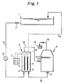
- FIG. 1 An example of the apparatus for performing oil-water separation according to the first aspect of the invention is shown in Fig. 1.
- Metal parts that have been subjected to press working and which have an emulsifiable water-insoluble oil film adhering to their surface are cleaned in a cleaning tank 1 by means of an aqueous solution that contains a sodium alkylsulfonate and a nonionic surfactant of a polyoxyethylene alkyl phenyl ether type as detergents and which has sodium sulfate added as a builder.
- the cleaning solution containing an oily contaminant such as the emulsifiable water-insoluble oil is supplied into a diaphragm electrolyzer 2 at an anode compartment 4 containing an anode 3 via a feed pipe 10 equipped with a valve 11 and a feed pump 12.
- the diaphragm electrolyzer 2 is divided into the anode compartment 4 and a cathode compartment 6 by a diaphragm 8 and they respectively contain the anode 3 and a cathode 5, which are supplied with a predetermined dc current from a power source 7.
- water is electrolyzed to generate hydrogen ions, which will cause of the loss of the surface activity of the anionic surface active substance such as the sodium alkylsulfonate in the oil-contaminated cleaning solution which has been fed into said anode compartment.
- anionic surface active substance such as the sodium alkylsulfonate
- the cleaning solution thus rendered acidic emerges from the anode compartment 4 and passes through a pipe 15 to be fed into an oil-water separation tank 9 via an inlet 13; in the oil-water separation tank 9, the cleaning solution is heated to a temperature higher than the cloud point of the nonionic surfactant of a polyoxyethylene alkyl phenyl ether type.
- the cleaning solution in the oil-water separation tank 9 needs only to be heated to a temperature in the range of 50 - 80°C, preferably 60 - 65°C, so that the oil content is selectively separated by flotation.
- the cleaning solution is allowed to stay within the oil-water separation tank 9 for a detention time of no more than about 20 minutes and the separated oil content is continuously discharged out of the system to flow into an oil tank 14 via a connection pipe 16.
- the oil-freed cleaning solution is withdrawn from the bottom of the oil-water separation tank 9 via an outlet 17.
- the cleaning solution from which the oil content and part of the surfactant have been removed flows through a pipe 18 connected to the outlet 17 such that it is fed into the cathode compartment 6 of the diaphragm electrolyzer 2 in which the cathode 5 is provided.
- water is electrolyzed to generate hydroxyl ions, which will neutralize the cleaning solution fed into said cathode compartment.
- the neutralized cleaning solution leaves the cathode compartment 6 and passes through a pipe 19 to return to the cleaning tank 1.
- the cleaning solution which has been adjusted to the initial pH in the cathode compartment 6 may be directly discharged out of the system without being returned to the cleaning tank 1.
- the cleaning solution to be treated is forced by a feed pump to circulate in a single pass through a closed loop starting with the cleaning tank, followed in order by the anode compartment, oil-water separation tank and cathode compartment and ending with the cleaning tank.
- a feed pump In order to break the emulsified oil particles in the cleaning solution, its pH must be made lower than the pKa value of the anionic surfactant and its temperature higher than the cloud point of the nonionic surfactant within the single pass.
- the throughput namely, the quantity of circulating flow has to be lowered as the pH or alkalinity of the cleaning solution increases.
- the smaller quantity of circulating flow reduces the flow rate of the liquid on the surface of the diaphragm, thereby increasing the likelihood of the contamination of the membrane and accelerating the increase of the electrolytic voltage.
- the second aspect of the invention has been accomplished in order to meet the above-described requirement. It relates to a method for oil-water separation of wastewater containing a surfactant and an oil content that has been emulsified by the action of said surfactant.
- the diaphragm electrolyzer used in the second aspect has an anode and a cathode provided in an anode compartment and a cathode compartment, respectively, which are spaced apart by a porous diaphragm; however, in the second aspect, the anode compartment of the diaphragm electrolyzer is supplied with the feed wastewater, part of which is passed through the diaphragm to enter the cathode compartment, from which it is discharged while the remainder of the wastewater is discharged from the anode compartment, thereby accomplishing the intended oil-water separation.
- an apparatus for water-oil separation of wastewater containing a surfactant and an oil content that has been emulsified by the action of said surfactant which comprises a diaphragm electrolyzer having an anode and a cathode provided in an anode compartment and a cathode compartment, respectively, that are spaced apart by a porous diaphragm, and a tank for oil water separation of the effluent from the anode compartment, said diaphragm electrolyzer being connected to said oil-water separation tank in such a way that the latter is supplied with the feed wastewater, which is withdrawn from the bottom of said oil-separation tank to be fed into the anode compartment of said diaphragm electrolyzer, with part of the effluent from the anode compartment being passed through the diaphragm to enter the cathode compartment, from which it is discharged while the remainder of the effluent is returned to the oil-water separation tank
- the tank for oil-water separation of the effluent from the anode compartment is preferably equipped with an electric heater.
- a wastewater receiving tank or receptacle may be provided above said oil-water separation tank and the two tanks are connected in such a way that the wastewater can be fed into the separation tank due to the difference in liquid level.
- the bottom of the oil-water separation tank is connected to the receiving tank via a feed pump and a return valve.
- a separate oil-water separation tank may be provided and connected in such a way that it can be supplied with the effluent from the cathode compartment; in this case, the bottom of said separation tank may be connected to the wastewater receiving tank.
- an oil receptacle may be provided in such a way that it is connected to the top of each separation tank.
- the wastewater receiving tank may be used either as a tank for receiving the wastewater containing both the surfactant used to clean the workpiece and the emulsified oil or as a tank in which the workpiece is directly cleaned.
- the pH of the wastewater in the anode compartment can be rendered lower than the pKa (acid dissociation index) of the anionic surfactant in water by diaphragm electrolysis and the electrical permeation of water from the anode compartment to the cathode compartment combines with the filter effect of the differential pressure (0 - 0.2 MPa) between the anode and cathode compartments to enrich the oil content not only in the anode compartment but also in the associated oil-water separation tank.
- the factor of enrichment is adjusted to be in the range of 0.5 - 5.
- Electrical permeation is a phenomenon that occurs when cations such as Na + electrophorese from the anode to the cathode compartment during electrolysis and it is characterized by the permeation of water from the anode to the cathode compartment through the diaphragm (which in the present invention is a microfiltration membrane having an average pore size of 0.1 - 3.0 ⁇ m).
- sodium phosphate or sodium tripolyphosphate and/or sodium sulfate may be incorporated in an amount of up to 30 mM in the wastewater to be treated and this is effective not only in preventing scale deposition on the cathode surface and the diaphragm on account of the hardness components such as calcium, magnesium and barium but also for increasing the electrical conductivity of the wastewater to be treated.
- the effluent from the anode compartment is returned to the associated oil-water separation tank, whereby the reaction for insolubilizing the anionic surfactant by reducing the pH is carried out not in the anode compartment but in the tank for oil-water separation of the effluent from the anode compartment and, in addition, the liquid flow rate on the side of the diaphragm facing the anode compartment is increased to 0.1 - 0.5 m/sec.
- an electric heater provided in the tank for oil-water separation of the effluent from the anode compartment is used to heat the effluent to a temperature above the cloud point of the nonionic surfactant, the efficiency of oil separation can be enhanced; in addition, the effluent from the cathode compartment may be introduced into the associated oil-separation tank, whereby the oil contaminant passing through the diaphragm can be separated by flotation to achieve a further improvement in the efficiency of oil-water separation.
- Surfactants that may be present in the wastewater to be treated in accordance with the second aspect of the invention include anionic surfactants such as organic sodium carboxylates, organic sodium sulfonates and organic sodium sulfate, and nonionic surfactants of various types such as polyoxyethylene alkyl phenyl ether, polyoxyethylene alkyl ether, polyethylene glycol, sorbitan fatty acid ester, polyoxyethylene sorbitan fatty acid ester and pluronic types.
- Inorganic builders that may be present in the wastewater include various kinds of sodium phosphate, sodium silicate and sodium borate.
- the wastewater to be treated has preferably an alkalinity in the range of 0.1 - 10.0.
- alkalinity means the quantity in milliliters of 0.1 N HCl required to titrate 10 ml of the wastewater feed to an end pH point of 4.8.
- the wastewater containing the emulsified oil is fed into the anode compartment of a diaphragm electrolyzer and the water is electrolyzed in accordance with the reaction scheme set forth below, whereby hydrogen ions are generated in the medium in the anode compartment: H 2 O ⁇ 1/2O 2 + 2H + + 2e -
- the generated hydrogen ions make the cleaning solution acidic.
- the sodium alkylsulfonate will undergo the following reaction: R-SO 3 - + H + ⁇ R-SO 3 H whereby hydrogen ion binds to the anionic group to cause the loss of surface activity of the anionic surfactant, thereby making it insoluble in water.
- the wastewater may be rendered acidic to a pH value of 1 - 7 and, for practical purposes, satisfactory results can be attained if the pH is within the range of 3 - 7.
- electrical permeation is another driving force to enrich the oil content.
- cations such as Na + electrophorese from the anode to the cathode compartment
- water permeates the diaphragm (having an average pore size of no more than 3 ⁇ m) to move from the anode to the cathode compartment, whereby the oil content of the electrolyzed wastewater in the anode compartment or the associated oil-water separation tank is sufficiently enriched.
- the pH adjusted wastewater emerging from the anode compartment of the diaphragm electrolyzer is then fed into the oil-water separation tank, where the temperature of the electrolyzed wastewater is raised to a specified value higher than the cloud point of the nonionic surfactant contained in the wastewater so that the oil is separated therefrom; the oil-separated wastewater is returned to the anode compartment of the diaphragm electrolyzer.
- the diaphragm electrolyzer and the porous diaphragm which are to be employed in the second aspect of the invention are identical to those used in the first aspect.
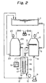
- FIG. 2 An example of the apparatus for performing oil-water separation according to the second aspect of the invention is shown in Fig. 2.
- a receptacle 1 holds wastewater containing an emulsified oil content.
- the wastewater is fed into an oil-water separation tank 2 via an inlet 5.
- the tank 2 is equipped with an electric heater 3 and an air vent valve 4.
- the wastewater emerging from the tank 2 via an outlet 6 is forced by a feed pump 9 into a diaphragm electrolyzer 13 at an anode compartment 15 containing an anode 14.
- the diaphragm electrolyzer 13 is divided into the anode compartment 15 and a cathode compartment 17 by a diaphragm 18 and they respectively contain the anode 14 and a cathode 16, which are supplied with a predetermined dc current from a power source 19.
- a diaphragm 18 In the anode compartment 15, water is electrolyzed to generate hydrogen ions, which will cause the loss of the surface activity of the anionic surface active substance such as the sodium alkylsufonate in the wastewater which has been fed into said anode compartment.
- the wastewater thus rendered acidic emerges from the anode compartment 15 of the diaphragm electrolyzer 13 to enter the oil-water separation tank 2 via an inlet 7; in the separation tank 2, the effluent is heated with the electric heater 3 to a temperature higher than the cloud point of the nonionic surfactant.
- the effluent fed into the oil-water separation tank 2 needs only to be heated to a temperature in the range of 50 - 80°C, preferably 60 - 70°C, so that the oil content is selectively separated by flotation.
- the effluent is allowed to stay within the oil-water separation tank 2 for a detention time of no more than about 20 minutes and the separated oil content is continuously or intermittently discharged out of the system to flow into an oil reservoir 8 whereas the aqueous phase is recovered from the tank 2 via the outlet 6 to return to the anode compartment 15.
- That part of the electrolyzed wastewater in the anode compartment 15 which has passed through the diaphragm 18 to flow into the cathode compartment 17 is fed into another oil-water separation tank 20 via an inlet 21 and, in that tank 20, the oil content that has passed through the diaphragm 18 is separated and sent to the oil reservoir 8 whereas the aqueous phase emerges from the bottom of the tank 20 via an outlet 22 to be returned to the receptacle 1.
- Shown by 23 is an air vent valve.
- the wastewater to be treated is subjected to oil-water separation as it circulates between the oil-water separation tank 2 and the anode compartment 15 of the diaphragm electrolyzer 13.
- the circulation loop is fitted with a pressure gage 10 and a pressure regulating valve 11.
- a valve 12 for returning the effluent from the anode compartment is operated to withdraw the aqueous phase into the receptacle 1 such that the pH of the effluent is maintained at a predetermined constant level.
- Fig. 2 showing the apparatus for implementing the method of oil-water separation in accordance with the second aspect, the electrolyzed wastewater from the anode compartment 15 is directly connected to the tank 2 for oil-water separation of the effluent from the anode compartment and both the anode 14 and the cathode 16 are fixed in position.
- the second aspect of the invention has had the following problems.
- the third aspect of the invention intends to provide a method and an apparatus for oil-water separation of wastewater containing an emulsified oil that are capable of the intended oil-water separation at a higher pH than in the second aspect and which adopt simple means of decontaminating the diaphragm and electrodes to thereby restore the desired permeate flow and voltage.
- the third aspect of the invention relates to a method for oil-water separation of wastewater containing a surfactant and an oil content that has been emulsified by the action of said surfactant.
- the diaphragm electrolyzer used in the third aspect has an anode and a cathode provided in an anode compartment and a cathode compartment, respectively, which are spaced apart by a porous diaphragm.
- the anode compartment of the diaphragm electrolyzer is supplied with the feed wastewater for electrolysis and part of the electrolyzed wastewater is passed through the diaphragm to enter the cathode compartment, from which it is discharged while the remainder of the electrolyzed wastewater is discharged from the anode compartment and thence introduced into a layer packed with an adhering material, where it is brought into contact with the adhering material and, thereafter, the effluent is directed to an oil-water separation step for accomplishing the intended oil-water separation.
- the polarities of the two electrodes are changed alternately at specified time intervals during the step of diaphragm electrolysis such that the anode compartment is switched to the cathode compartment and vice versa.
- an apparatus for water-oil separation of wastewater containing a surfactant and an oil content that has been emulsified by the action of said surfactant which comprises a diaphragm electrolyzer having an anode and a cathode provided in an anode compartment and a cathode compartment, respectively, that are spaced apart by a porous diaphragm, a column packed with an adhering material, and a tank for oil-water separation of the effluent from the anode compartment, with the diaphragm electrolyzer, the packed column and the oil-water separation tank being interconnected in such a way that the separation tank is supplied with the feed wastewater, which is withdrawn from the bottom of said separation tank to be fed into the anode compartment of said diaphragm electrolyzer, with part of the effluent from the anode compartment being passed through the diaphragm to enter the cathode compartment, from which it is discharged while the remainder of
- the diaphragm electrolyzer is adapted to be capable of changing the polarities of the two electrodes alternately such that the anode is switched to the cathode compartment and vice versa while, at the same time, the pipes connecting to the anode and cathode compartments are accordingly switched.
- the third aspect of the invention is similar to the second aspect in many ways, the following description concerns only the difference, which is the provision of a coalescer, or a layer packed with an adhering material, between the diaphragm electrolyzer and the tank for oil-water separation of the effluent from the anode compartment.
- the wastewater to be treated which contains an emulsified oil is supplied into the tank for oil-water separation of the effluent from the anode compartment and it is then withdrawn from the bottom of said separation tank to be fed into the anode compartment of the diaphragm electrolyzer and part of the wastewater electrolyzed in the anode compartment is passed through the diaphragm to enter the cathode compartment, from which it is discharged where the remainder of the electrolyzed wastewater is returned to the associated separation tank.
- the electrolyzed wastewater in the anode compartment is partly returned to the associated separation tank after it is directed in an upward flow into the layer packed with an adhering material such that it is brought into contact with said adhering material.
- oil-water separation effect By causing the oil particles in the electrolyzed wastewater to attach to the adhering material, the oil particles will collide at an increased rate and their coalescing and coarsening are sufficiently promoted to provide the so-called "oil-water separation effect" of the coalescer.
- This effect combines synergistically with the oil-water separation effect of diaphragm electrolysis to increase the specified pH for oil-water separation and thereby improve the overall efficiency of oil-water separation.
- the layer packed with the adhering material which works as a coalescer may assume a cylindrical, rectangular or any other shape; the adhering material with which the layer is to be packed may be of any nature as long as it is chemically stable and has a large specific surface area, and an advantageous example of its shape is an aggregate of particulate matter or fibers.
- Exemplary particulate adhering materials include quartz sand, zeolite and kaolin, and exemplary fibrous adhering materials include slag wool and synthetic fibers.
- the larger the volume of the layer packed with the adhering material the longer the contact time and the more effective the layer is as a coalescer.
- the superficial velocity (SV in h -1 ) of the electrolyzed wastewater passing through the layer packed with the adhering material will suffice if it is within the range of 20 - 200 h -1 .
- the additional advantage of causing the oil particles to attach to the adhering material is that they will have an increased density on the adhering material to achieve more efficient contact between the oil content and the electrolyzed wastewater.
- hydrophobic organic matter, such as the nonionic surfactant, in the electrolyzed wastewater or the anionic surfactant which has become no longer dissociable into an acid on account of the acidic nature of the electrolyzed wastewater can be extracted with the oil content and, hence, can be rejected together with the latter.
- the polarities of the two electrodes are changed alternately at specified time intervals such that the anode is switched to the cathode and vice versa at specified time intervals while, at the same time, the pipes connecting to the anode and cathode compartments are accordingly switched.
- the wastewater in the anode compartment is usually acidic in nature, so part of the anionic surfactant will become insoluble and the resulting insoluble matter, as well as the broken oil particles that are no longer in an emulsified state will occasionally form a deposit that contaminates the surfaces of the electrodes and the diaphragm.
- the wastewater in the cathode compartment is alkaline, so insoluble hydroxides of alkaline earth metals may be generated to form a deposit that adheres to the surfaces of the electrodes and the diaphragm.
- the interval of polarity changes may be determined within the range of 4 - 72 h.
- the wastewater to be treated in the third aspect of the invention and the surfactants to be present in the wastewater are identical to those described in connection with the second aspect.
- the mechanism by which the wastewater containing an emulsified oil is treated in the anode compartment of the diaphragm electrolyzer, as well as the effect of electrical permeation that is utilized to enrich the oil content are also identical to those described in connection with the second aspect.
- the pH adjusted effluent from the anode compartment is returned to the anode compartment in the same manner as in the second aspect.
- the diaphragm electrolyzer and the porous diaphragm which are to be employed in the third aspect of the invention are identical to those used in the first aspect.
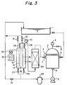
- FIG. 3 An example of the apparatus for performing oil-water separation according to the third aspect of the invention is shown in Fig. 3.
- a receptacle 1 holds wastewater containing an emulsified oil content.
- the wastewater is fed into an oil-water separation tank 2 via an inlet 5.
- the tank 2 is equipped with an electric heater 3 and an air vent valve 4.
- the wastewater emerging from the tank 2 via an outlet 6 is forced by a feed pump 9 to pass through a prefilter 24 into a diaphragm electrolyzer 13 at an anode compartment 15 containing an anode 14.
- the diaphragm electrolyzer 13 is divided into the anode compartment 15 and a cathode compartment 17 by a diaphragm 18 and they respectively contain the anode 14 and a cathode 16, which are supplied with a predetermined dc current from a power source 19.
- a diaphragm 18 In the anode compartment 15, water is electrolyzed to generate hydrogen ions, which will cause the loss of the surface activity of the anionic surface active substance such as the sodium alkylsulfonate in the wastewater which has been fed into said anode compartment.
- the wastewater thus rendered acidic emerges from the anode compartment 15 of the diaphragm electrolyzer 13 to pass through a column 25 packed with an adhering material and enter the oil-water separation tank 2 via an inlet 7; in the separation tank 2, the effluent is heated with the electric heater 3 to a temperature higher than the cloud point of the nonionic surfactant.
- the effluent fed into the oil-water separation tank 2 needs only to be heated to a temperature in the range of 50 - 80°C, preferably 60 - 70°C, so that the oil content is selectively separated by flotation.
- the effluent is allowed to stay within the oil-water separation tank 2 for a detention time of no more than about 20 minutes and the separated oil content is continuously or intermittently discharged out of the system whereas the aqueous phase is recovered from the tank 2 via the outlet 6 to return to the anode compartment 15, thereby accomplishing the intended oil-water separation.
- the electrolyzed wastewater flowing from the anode compartment 15 past the diaphragm 18 to enter the cathode compartment 17 will emerge therefrom and passes through a valve 31 to be returned to the receptacle 1.
- a switching board 32 connected to the power source 19 is operated to change the polarity of the voltage applied to the electrolyzer 13 in such a way that the anode compartment 15 is switched to cathode compartment and the cathode compartment 17 to anode compartment while, at the same time, valves 26, 28 and 31 are closed whereas valves 27, 29 and 30 are opened.
- the contaminants are removed from the surfaces of the diaphragm and the electrodes to thereby restore the permeate flow and the electrolytic voltage.
- Fig. 3 showing the apparatus for performing oil-water separation according to the third aspect of the invention, the effluent (electrolyzed wastewater) from the anode compartment 15 passes through the packed column 25 to be returned to the oil-water separation tank 2.
- the fourth aspect of the invention intends to provide a method and an apparatus for oil-water separation of wastewater containing an emulsified oil that are capable of increasing the flow rate of the wastewater on the anode side of the diaphragm without increasing the quantity of the feed to the packed column or the oil-water separation tank for the effluent from the anode compartment.
- the fourth aspect of the invention relates to a method for oil-water separation of wastewater containing a surfactant and an oil content that has been emulsified by the action of said surfactant.
- the diaphragm electrolyzer used in the fourth aspect has an anode and a cathode provided in an anode compartment and cathode compartment, respectively, which are spaced apart by a porous diaphragm.
- the anode compartment of the diaphragm electrolyzer is supplied with the feed wastewater for electrolysis and part of the electrolyzed wastewater is passed through the diaphragm to enter the cathode compartment, from which it is discharged while the remainder of the electrolyzed wastewater is discharged from the anode compartment.
- the electrolyzed wastewater discharged from the anode compartment is introduced into the intermediate portion of a gas-liquid separator and part of the influent is withdrawn from the top of the gas-liquid separator and introduced into a layer packed with an adhering material, where it is brought into contact with the adhering material and, thereafter, the effluent is directed to an oil-water separation step for accomplishing the intended oil-water separation while, at the same time, the remainder is withdrawn from the bottom of the gas-liquid separator to be returned to mix with the feed to the electrolysis step.
- the polarities of the two electrodes are changed alternately at specified time intervals during the step of diaphragm electrolysis such that the anode compartment is switched to the cathode compartment and vice versa.
- an apparatus for oil-water separation of wastewater containing a surfactant and an oil content that has been emulsified by the action of said surfactant which comprises a diaphragm electrolyzer having an anode and a cathode provided in an anode compartment and a cathode compartment, respectively, that are spaced apart by a porous diaphragm, a gas-liquid separator, a column packed with an adhering material, and a tank for oil-water separation of the effluent from the anode compartment, with the diaphragm electrolyzer, the gas-liquid separator, the packed column and the oil-water separation tank being interconnected by channels in such a way that the separation tank is supplied with the feed wastewater, which is withdrawn from the bottom of said separation tank to be fed into the anode compartment of said diaphragm electrolyzer, with part of the electrolyzed wastewater being passed through the diaphragm to enter the cathode compartment
- the diaphragm electrolyzer is adapted to be capable of changing the polarities of the two electrodes alternately such that the anode is switched to the cathode compartment and vice versa while, at the same time, the pipes connecting to the anode and cathode compartments are accordingly switched.
- the fourth aspect of the invention is similar to the third aspect in many ways, the following description concerns only the difference, which is the provision of a gas-liquid separator between the diaphragm electrolyzer and the column packed with an adhering material.
- the effluent from the anode compartment of the diaphragm electrolyzer is introduced into the intermediate portion of the gas-liquid separator and part of the influent is withdrawn from the top of the gas-liquid separator to be fed into the packed column whereas the remainder is withdrawn from the bottom of the separator to be returned to a suction port of a feed pump.
- the flow rate of the feed wastewater on the anode side of the diaphragm can be increased without increasing the quantity of the feed to either the packed column or the oil-water separation tank for the effluent from the anode compartment.
- the gas-liquid separator has the added advantage of providing an oil floating action due to the tiny oxygen bubbles in the wastewater which have been generated by electrolysis.
- Yet another advantage of the fourth aspect of the invention is that in order to increase the throughput of the overall system, one needs only to increase the sizes of the electrolyzer and the feed pump and there is no need to revamp the packed column and the oil-water separation tank for the effluent from the anode compartment.
- the influent into the gas-liquid separator has desirably the longest possible detention time but 0.5 - 2 min will normally suffice.
- the gas-liquid separator may be fitted with a perforated plate for promoting the intended gas-liquid separation.
- the column packed with an adhering material is provided as a coalescer between the gas-liquid separator and the oil-water separation tank for the effluent from the anode compartment.
- the electrolyzed wastewater withdrawn from the top of the gas-liquid separator is returned to the associated oil-water separation tank after it is directed in an upward flow into the packed column such that it is brought into contact with the adhering material.
- the polarities of the two electrodes may be changed alternately and the resulting advantages are also the same as described in connection with the third aspect.
- the wastewater to be treated in the fourth aspect and the surfactants to be present in the wastewater are also identical to those described in connection with the third aspect.
- the pH adjusted effluent from the anode compartment is returned to the anode compartment in the same manner as in the second aspect.
- the diaphragm electrolyzer and the porous diaphragm which are to be employed in the fourth aspect are also identical to those used in the first aspect.
- FIG. 5 An example of the apparatus for performing oil-water separation according to the fourth aspect of the invention is shown in Fig. 5.
- a receptacle 1 holds wastewater containing an emulsified oil content.
- the wastewater is fed into an oil-water separation tank 2 via an inlet 5.
- the tank 2 is equipped with an electric heater 3 and an air vent valve 4.
- the wastewater emerging from the tank 2 via an outlet 6 is forced by a feed pump 9 into a diaphragm electrolyzer 13 at an anode compartment 15 containing an anode 14.
- the diaphragm electrolyzer 13 is divided into the anode compartment 15 and a cathode compartment 17 by a diaphragm 18 and they respectively contain the anode 14 and a cathode 16, which are supplied with a predetermined dc current from a power source 19.
- a diaphragm 18 In the anode compartment 15, water is electrolyzed to generate hydrogen ion, which will cause the loss of the surface activity of the anionic surface active substance such as the sodium alkylsulfonate in the wastewater which has been fed into said anode compartment.
- the wastewater thus rendered acidic emerges from the anode compartment 15 of the diaphragm electrolyzer 13 to be introduced into the intermediate portion of a gas-liquid separator 33 and part of the influent is withdrawn from the top and passed through a column 25 packed with an adhering material and thence supplied into the oil-water separation tank 2 via an inlet 7; in the separation tank 2, the effluent is heated with the electric heater 3 to a temperature higher than the cloud point of the nonionic surfactant.
- the remainder of the influent into the gas-liquid separator 33 is withdrawn from the bottom and returned to the suction port of the feed pump 9.
- the effluent fed into the oil-water separation tank 2 needs only to be heated to a temperature in the range of 50 - 80°C, preferably 60 - 70°C, so that the oil content is selectively separated by flotation.
- the effluent is allowed to stay within the oil-water separation tank 2 for a detention time of no more than about 20 minutes and the separated oil content is continuously or intermittently discharged out of the system whereas the aqueous phase is recovered from the tank 2 via the outlet 6 to return to the anode compartment 15.
- the electrolyzed wastewater flowing from the anode compartment 15 past the diaphragm 18 to enter the cathode compartment 17 will emerge therefrom and passes through a valve 31 to be returned to the receptacle 1.
- a switching board 32 connected to the power source 19 is operated to change the polarity of the voltage applied to the electrolyzer 13 in such a way that the anode compartment 15 is switched to cathode compartment and the cathode compartment 17 to anode compartment while, at the same time, valves 26, 28 and 31 are closed whereas valves 27, 29 and 30 are opened.
- the contaminants are removed from the surfaces of the diaphragm and the electrodes to thereby restore the permeate flow and the electrolytic voltage.
- the diaphragm electrolyzer was a sealed rectangular type made of poly(vinyl chloride).
- the anode was a titanium plate with an area of 0.1 m 2 having a platinum plate deposited thereon and so was the cathode.
- the diaphragm was a MF membrane made of an organic synthetic polymer.
- the oil-water separation tank had a capacity of 36 L with a built-in electric heater of 1 kw.
- a detergent was prepared from an aqueous solution containing 15% of a nonionic surfactant of a polyoxyethylene alkyl phenyl ether type having a cloud point of 49°C and 3.5% of sodium sulfate.
- the detergent was diluted with water to a concentration of 5% and had the pH adjusted with sodium hydroxide to 8.7, thereby preparing a cleaning solution of 200 L.
- the cleaning solution was used with its temperature controlled at 45°C.
- An emulsifiable water-insoluble rust preventive oil was used in the test. This oil contained a large amount of a barium alkylsulfonate as a rust inhibitor.
- the cleaning solution in the cleaning tank was pumped into the anode compartment of the diaphragm electrolyzer at a flow rate of 200 L/h.
- the electrolytic current was set at 1.2 A such that the cleaning solution emerging from the anode compartment would be in the range of 5.0 - 5.0.
- the corresponding electrolytic voltage was about 6 V.
- the cleaning solution exiting from the anode compartment was introduced into the oil-water separation tank, where it was heated to effect oil-water separation.
- the temperature setting of the built-in heater in the separation tank was 65°C.
- the oil-freed cleaning solution was sent to the cathode compartment of the diaphragm electrolyzer.
- the cleaning solution exiting from the cathode compartment was returned to the cleaning tank.
- the cleaning solution had a pH of 8.8 as it emerged from the cathode compartment.
- Example 2 An apparatus for oil-water separation of the same design as used in Example 1 was applied, except that the power supply to the diaphragm electrolyzer was turned off such that no electrolytic treatment would be performed.
- a test for oil-water separation was conducted using the same cleaning solution and rust preventive oil as employed in Example 1. When the cleaning solution having the rust preventive oil dispersed therein was not electrolyzed, no oil-water separation occurred in the cleaning solution.
- a detergent was prepared rom an aqueous solution containing 15% of a nonionic surfactant of a polyoxyethylene alkyl phenyl ether type having a cloud point of 49°C, 6% of a nonionic surfactant of a pluronic type having a cloud point of 29°C and 3.5% of sodium sulfate.
- the detergent was diluted with water to a concentration of 5% and had the pH adjusted with sodium hydroxide to 9.7, thereby preparing a cleaning solution of 200 L.
- the cleaning solution was used with its temperature controlled at 40°C.
- a mixture of a water-soluble cutting oil of type W1, an emulsifiable water-insoluble rust preventive oil and a non-emulsifiable water-insoluble cutting oil was used in the test.
- the water-soluble cutting oil, the rust preventive oil and the water-insoluble cutting oil were added at respective concentrations of 0.1%, 1.0% and 1.0%.
- the water-insoluble cutting oil had a small content of an anionic surface active substance; in contrast, the water-soluble cutting oil contained about 25% of an anionic surfactant (e.g. sodium alkylsulfonate or sodium alkylcarboxylate) and its mineral oil content was about 60%.
- an anionic surfactant e.g. sodium alkylsulfonate or sodium alkylcarboxylate
- Example 2 The testing equipment and procedure employed in Example 2 were identical to those used in Example 1; however, in order to ensure that the cleaning solution existing from the anode compartment would have a pH of 5.0 - 5.5, the electrolytic current was set at 10 A. The corresponding electrolytic voltage was about 20 V. The cleaning solution had a pH of 9.9 as it emerged from the cathode compartment.
- Example 2 The results of the test conducted in Example 2 are also shown in Table 1, from which one can see that effective oil-water separation was accomplished in accordance with the first aspect of the invention.
- Example 2 the nonionic surfactant in the cleaning solution was not found to be separated by flotation together with the oil.
- Example 2 An apparatus for oil-water separation of the same design as used in Example 2 was applied, except that the power supply to the diaphragm electrolyzer was turned off such that no electrolytic treatment would be performed.
- a test for oil-water separation was conducted on a cleaning solution in which the same water-soluble cutting oil, rust preventive oil and water-insoluble cutting oil as used in Example 2 were dispersed.
- An apparatus for oil-water separation was constructed according to the design of the second aspect of the invention shown in Fig. 2 and it was used in testing the oil-water separation of wastewater containing an emulsified oil.
- the diaphragm electrolyzer was a sealed rectangular type made of polypropylene resin.
- Each of the anode and the cathode was a Pt-plated Ti electrode having an effective area of 0.1 m 2 .
- the diaphragm was a MF membrane made of an organic synthetic polymer having a nominal pore size of 0.5 ⁇ m.
- the tank for oil-water separation of the effluent from the anode compartment had a capacity of 36 L with a built-in electric heater of 1 kw.
- the tank for oil-water separation of the effluent from the cathode compartment had a capacity of 10 L.
- Liquid waste coolant was used in the test as the wastewater containing an emulsified oil.
- the liquid waste coolant was prepared by 30-fold dilution of a water-soluble cutting oil of type W1 and had an oil concentration of 1.8% and a pH of 8.8. After adding 0.05% of sodium tripolyphosphate to it, the liquid waste was first charged into the receptacle 1 from which it was injected into the tank 2 for oil-water separation of the effluent from the anode compartment. The injection of the liquid waste was 240 L.
- the liquid waste was electrolyzed at a current of 20 A as it was forced by pump 9 to circulate between the anode compartment 15 of the electrolyzer 13 and the separation tank 2 at a flow rate of 8 L/min.
- the corresponding electrolytic voltage was about 56 V.
- the temperature setting of the electric heater 3 in the separation tank 2 was 55°C.
- the effluent from the cathode compartment 17 flowed at a rate of 0.32 L/min and had a pH of 11.3 and an oil concentration of 0.06%. The effluent was then returned to the receptacle 1.
- valve 12 was operated to have the effluent return continuously to the receptacle 1 such that its flow rate would be 0.15 L/min. Thereafter, the pH of the effluent stabilized in the neighborhood of 4.5. The effluent was found have an oil concentration of 0.3% at the outlet 6.
- the time-dependent profile of the oil concentration of the liquid waste in the receptacle 1 is shown in Table 2.
- the test was stopped and the oil was withdrawn from the separation tank 2 and the oil-separation tank 20 for the effluent from the cathode compartment via respective oil drain valves and a total of about 3.1 L of the oil was recovered.
- the second aspect of the invention was applied to treat wastewater containing an emulsified oil, which was an oil-containing cleaning solution of the type described below.
- a detergent was prepared from an aqueous solution containing 20% of a nonionic surfactant of a polyoxyethylene alkyl phenyl ether type having a cloud point of 49°C and 3.0% of sodium sulfate.
- a 5% aqueous solution of the detergent was prepared in the receptacle 1 and adjusted to have a temperature of 45°C and its pH adjusted to 9.8 with sodium tripolyphosphate and the thus prepared cleaning solution was used in a test for oil-water separation.
- the oil to be separated was an emulsifiable water-insoluble rust preventive oil.
- This oil contained a large amount of a barium alkylsulfonate as a rust inhibitor.
- Four liters of the oil was charged into the cleaning tank to give an initial oil concentration of 2%.
- the latter was agitated with a cascaded pump (3,600 rpm) for 30 min at a flow rate of 15 L/min.
- Example 4 The testing equipment and procedure employed in Example 4 were identical to those used in Example 3, except that electrolysis was performed at a current of 25 A; the corresponding electrolytic voltage was about 29 V.
- the temperature setting of the electric heater 3 in the tank 2 for oil-water separation of the effluent from the anode was 65°C.
- the effluent from the cathode compartment 17 flowed at a rate of 0.28 L/min and had a pH of 11.5 and an oil concentration of 0.15%.
- valve 12 was operated to have the effluent return continuously to the receptacle 1 such that its flow rate would be 0.1 L/min. Thereafter, the pH of the effluent stabilized in the neighborhood of 2.5. The effluent was found to have an oil concentration of 0.6% at the outlet 6.
- the time-dependent profile of the oil concentration of the cleaning solution in the receptacle 1 is shown in Table 2.
- the test was stopped and the oil was withdrawn from the separation tanks 2 and 20 via respective oil drain valves and a total of about 3.5 L of the oil was recovered, indicating that part of the nonionic surfactant in the cleaning solution was also separated by flotation together with the oil.
- continuous oil-water separation can be accomplished at low cost and with high efficiency on a wide variety of cleaning solutions including not only those contaminated by non-emulsifiable water-insoluble oils typified by press working oils and rolling mill oils but also those contaminated by water-soluble oils containing anionic or nonionic surfactants, as well as those contaminated by emulsifiable water-insoluble oils incorporating anionic surface active substances.
- the invention is also applicable to the oil-water separation of wastewater containing an emulsified oil as exemplified by water-soluble, liquid waste cutting oils and coolants.
- An apparatus for oil-water separation was constructed according to the design of the third aspect of the invention shown in Fig. 3 and it was used in testing the oil-water separation of wastewater containing an emulsified oil.
- the diaphragm electrolyzer was a sealed rectangular type made of polypropylene resin.
- Each of the anode and the cathode was a Pt-plated Ti electrode having an effective area of 0.1 m 2 .
- the diaphragm was a MF membrane made of an organic synthetic polymer having a nominal pore size of 0.5 ⁇ m.
- the layer packed with an adhering material was provided from ADVANTEC CORP.
- the tank for oil-water separation of the effluent from the anode compartment had a capacity of 36 L.
- the wastewater containing an emulsified oil which was to be treated in Example 5 was warm cleaning water containing a water-soluble cutting oil of type W1.
- This cleaning water was subjected to continuous oil-water separation in the following manner. First, city water having 0.02% of sodium tripolyphosphate added was charged into the cleaning tank 1 and the oil-water separation tank 2 for the effluent from the anode compartment. The total water charge was 240 L. The water had a pH of 8.9 and it was held at 50°C by means of the electric heater built in the cleaning tank 1. In the next step, a water-soluble cutting oil of type W1, No. 1 available from company X was injected continuously into the cleaning tank 1 at a flow rate of 1.3 mL/min. The cleaning water in the tank 1 was stirred with an agitator to disperse the water-soluble cutting oil.
- the cleaning water thus prepared was forced by the pump 9 to circulate in a loop consisting of the anode compartment 15 of the electrolyzer 13, the packed layer 25 and the separation tank 2 at a flow rate of 8 L/min while electrolysis was conducted at a constant current of 25 amperes.
- the electrode 14 was the anode whereas the electrode 16 was the cathode, with valves 26, 28 and 31 being fully open but valves 27, 29 and 30 fully closed.
- the effluent from the cathode compartment was returned to the cleaning tank 1 at a flow rate of 0.42 L/min with the pH being in the neighborhood of 11.0.
- valve 12 was operated to have the effluent return continuously to the cleaning tank 1 such that its flow rate would be 0.45 L/min Thereafter, the pH of the effluent stabilized in the neighborhood of 6.0.
- the oil separated by flotation in the separation tank 2 was discharged and analysis of the oil concentration and TOC (total organic carbon concentration) of the cleaning water in the tank 1 was carried out. In addition, the electrolytic voltage was recorded for each analysis.
- Figs. 4a and 4b show the time-dependent profiles of the oil concentration and TOC of the cleaning water
- Fig. 4c shows the profile of electrolytic voltage.
- a comparative test for oil-water separation was made with the same apparatus and under the same conditions as in Example 5, except that the packed layer 25 was not provided and that no polarity changes were effected.
- the data of the comparative test are also shown in Fig. 4. Obviously, in the absence of the packed layer, no effective oil-water separation could be accomplished at a fairly high pH (6.0 in the comparative case). In order to perform effective oil-water separation of the cleaning water in the absence of the packed layer 25, the return flow to the cleaning tank 1 had to be reduced while, at the same time, the pH of the effluent from the anode compartment had to be lowered to 4.5.
- the electrolytic voltage which was about 30 volts at the start of the electrolysis increased gradually and 48 h later, it became as high as 95 volts. Since the temperature of the effluent from the cathode compartment at that time was 85°C which was close to the heat resisting limit of the electrolyzer, the test was suspended.
- An apparatus for oil-water separation was constructed according to the design of the fourth aspect of the invention shown in Fig. 5 and it was used in testing the oil-water separation of wastewater containing an emulsified oil.
- the diaphragm electrolyzer was a sealed rectangular type made of polypropylene resin.
- Each of the anode and the cathode was a Pt-plated Ti electrode having an effective area of 0.2 m 2 .
- the diaphragm was a MF membrane made of an organic synthetic polymer having a nominal pore size of 0.5 ⁇ m.
- the packing material was provided from ADVANTEC CORP.
- the tank for oil-water separation of the effluent from the anode had a capacity of 36 L and the gas-liquid separator 33 had a capacity of 10 L.
- the wastewater containing an emulsified oil which was to be treated in Example 6 was warm cleaning water containing a water-soluble cutting oil of type W1.
- This cleaning water was subjected to continuous oil-water separation in the following manner. First, city water was charged into the cleaning tank 1 and the oil-water separation tank 2 for the effluent from the anode compartment. The total water charge was 240 L. The water was held at 50°C by means of the electric heater build in the cleaning tank 1. In the next step, a water-soluble cutting oil of type W1, No. 1 available from company X was injected continuously into the cleaning tank 1 at a flow rate of 3.0 mL/min. The water in the cleaning tank 1 was stirred with an agitator to disperse the water-soluble cutting oil.
- the cleaning water thus prepared was forced by the pump 9 to flow at a rate of 16 L/min while electrolysis was conducted at a constant current of 50 amperes, with the valve 34 being adjusted to provide a flow quantity of 8 L/min from the gas-liquid separator 33 to the packed column 25 whereas the valve 35 was adjusted to provide a return flow of 8 L/min to the suction port of the feed pump 9.
- the electrode 14 was the anode whereas the electrode 16 was the cathode, with valves 26, 28 and 31 being fully open but valves 27, 29 and 30 fully closed.
- the effluent from the cathode compartment was returned to the cleaning tank 1 at a flow rate of 0.9 L/min with the pH being in the neighborhood of 11.0.
- valve 12 was operated to have the effluent return continuously to the cleaning tank 1 such that its flow rate would be 0.9 L/min. Thereafter, the pH of the effluent stabilized in the neighborhood of 6.0.
- the oil separated by flotation in the separation tank 2 was discharged and analysis of the oil concentration of the cleaning water in the tank 1 was carried out.
- Fig. 6 shows the time-dependent profile of the oil concentration of the cleaning water.
- the invention relates to a method for oil-water separation of a cleaning solution in an oil-water separation step which comprises the steps of feeding the contaminated cleaning solution into a diaphragm electrolyzer.
Landscapes
- Chemical & Material Sciences (AREA)
- Physics & Mathematics (AREA)
- Thermal Sciences (AREA)
- Chemical Kinetics & Catalysis (AREA)
- Analytical Chemistry (AREA)
- Life Sciences & Earth Sciences (AREA)
- Hydrology & Water Resources (AREA)
- Engineering & Computer Science (AREA)
- Environmental & Geological Engineering (AREA)
- Water Supply & Treatment (AREA)
- Organic Chemistry (AREA)
- Water Treatment By Electricity Or Magnetism (AREA)
Applications Claiming Priority (8)
| Application Number | Priority Date | Filing Date | Title |
|---|---|---|---|
| JP32714095A JPH09164303A (ja) | 1995-12-15 | 1995-12-15 | 洗浄液の油水分離方法及び装置 |
| JP327140/95 | 1995-12-15 | ||
| JP156384/96 | 1996-05-29 | ||
| JP15638496A JPH09313805A (ja) | 1996-05-29 | 1996-05-29 | 乳化油分含有排水の油水分離方法及び装置 |
| JP262313/96 | 1996-09-12 | ||
| JP8262313A JPH1085563A (ja) | 1996-09-12 | 1996-09-12 | 乳化油分含有排水の油水分離方法及び装置 |
| JP32488196A JP3358786B2 (ja) | 1996-11-21 | 1996-11-21 | 乳化油分含有排水の油水分離方法及び装置 |
| JP324881/96 | 1996-11-21 |
Publications (2)
| Publication Number | Publication Date |
|---|---|
| EP0779089A2 true EP0779089A2 (de) | 1997-06-18 |
| EP0779089A3 EP0779089A3 (de) | 1997-12-17 |
Family
ID=27473410
Family Applications (1)
| Application Number | Title | Priority Date | Filing Date |
|---|---|---|---|
| EP96120209A Withdrawn EP0779089A3 (de) | 1995-12-15 | 1996-12-16 | Verfahren und Vorrichtung zum Abtrennen von Öl aus Abwasser, das emulgiertes Öl enthält |
Country Status (4)
| Country | Link |
|---|---|
| US (4) | US5876589A (de) |
| EP (1) | EP0779089A3 (de) |
| KR (1) | KR100415405B1 (de) |
| CA (1) | CA2192889C (de) |
Cited By (1)
| Publication number | Priority date | Publication date | Assignee | Title |
|---|---|---|---|---|
| CN101602529B (zh) * | 2009-07-06 | 2012-08-22 | 西南铝业(集团)有限责任公司 | 一种铝板热轧乳液的破乳方法及系统 |
Families Citing this family (14)
| Publication number | Priority date | Publication date | Assignee | Title |
|---|---|---|---|---|
| US5876589A (en) * | 1995-12-15 | 1999-03-02 | Ebara Corporation | Method and apparatus for separating oil from water in wastewater containing an emulsified oil |
| RU2119802C1 (ru) * | 1996-12-18 | 1998-10-10 | Стерилокс Текнолоджиз, Инк. | Установка для электрохимической обработки жидкой среды (варианты) |
| US6113765A (en) * | 1997-10-17 | 2000-09-05 | The Texas A&M University System | Methods for enhanced resolution of hydrocarbon continuous emulsions or dispersions with conductivity modifiers |
| KR20000057105A (ko) * | 1998-12-28 | 2000-09-15 | 오오자와 슈지로 | 수용성 윤활유제의 살균장치 |
| US7604685B2 (en) * | 2004-11-22 | 2009-10-20 | Porous Media Corp | Method for the selective extraction of acids |
| CN1321905C (zh) * | 2005-09-22 | 2007-06-20 | 胡德仁 | 氧化电解和粒子群电解联合处理船舶乳化油废水的方法 |
| KR100982203B1 (ko) | 2010-06-07 | 2010-09-14 | (주)클레슨 | 멀티형 유수 분리장치 |
| US9573079B2 (en) | 2013-10-31 | 2017-02-21 | General Electric Company | Article and apparatus for enhancing the coalescence of a dispersed phase from a continuous phase in an emulsion |
| US9433878B2 (en) | 2013-10-31 | 2016-09-06 | General Electric Company | Electrostatic coalescer for coalescing a dispersed phase from a continuous phase in an emulsion |
| RU189420U1 (ru) * | 2018-11-06 | 2019-05-22 | федеральное государственное бюджетное образовательное учреждение высшего образования "Ульяновский государственный университет" | Коалесцентный фильтр с электролизером для очистки сточных вод на нефтяных предприятиях |
| US11090580B2 (en) | 2019-08-08 | 2021-08-17 | Saudi Arabian Oil Company | Dewatering a hydrocarbon storage tank |
| US12196713B2 (en) | 2021-08-24 | 2025-01-14 | Saudi Arabian Oil Company | Convex ultrasonic sensor for weld inspection |
| CN114506896B (zh) * | 2022-01-27 | 2023-02-14 | 华南理工大学 | 正壬醇在分离煤化工含油废水中的乳化油的应用及方法 |
| CN118064180B (zh) * | 2024-04-19 | 2024-07-12 | 长沙华时捷环保科技发展股份有限公司 | 炼油厂污油脱水、脱固、回收油相的方法 |
Family Cites Families (9)
| Publication number | Priority date | Publication date | Assignee | Title |
|---|---|---|---|---|
| DE3739580A1 (de) * | 1987-11-23 | 1989-06-01 | Battelle Institut E V | Verfahren und vorrichtung zur spaltung eines dispersen systems in einer elektrochemischen zelle |
| US4948476A (en) * | 1989-07-20 | 1990-08-14 | Bend Research, Inc. | Hybrid chromium recovery process |
| DE4003737A1 (de) * | 1990-02-08 | 1991-08-14 | Penth Synthesechemie | Verfahren zum spalten von emulsionen |
| US5164480A (en) * | 1991-08-20 | 1992-11-17 | Union Camp Corporation | Method for the manufacture of tall oils |
| DE4408797C2 (de) * | 1994-03-15 | 1996-11-07 | Bernd Dr Penth | Verfahren zur Stabilisierung und zur Spaltung von Kühlschmiermitteln |
| JPH08187402A (ja) * | 1995-01-06 | 1996-07-23 | Tokico Ltd | 油水分離装置 |
| DE19506242C2 (de) * | 1995-02-23 | 1998-05-20 | Metallgesellschaft Ag | Verfahren zur direkten elektrochemischen Oxidation von sulfithaltigen Lösungen, insbesondere Abwässern aus Gasreinigungsanlagen |
| JPH08257303A (ja) * | 1995-03-24 | 1996-10-08 | Mitsubishi Materials Corp | 油分浮上処理方法及び装置 |
| US5876589A (en) * | 1995-12-15 | 1999-03-02 | Ebara Corporation | Method and apparatus for separating oil from water in wastewater containing an emulsified oil |
-
1996
- 1996-12-13 US US08/768,024 patent/US5876589A/en not_active Expired - Fee Related
- 1996-12-13 CA CA002192889A patent/CA2192889C/en not_active Expired - Fee Related
- 1996-12-13 KR KR1019960065357A patent/KR100415405B1/ko not_active Expired - Fee Related
- 1996-12-16 EP EP96120209A patent/EP0779089A3/de not_active Withdrawn
-
1998
- 1998-11-18 US US09/195,251 patent/US6110352A/en not_active Expired - Fee Related
- 1998-11-18 US US09/195,250 patent/US6136178A/en not_active Expired - Fee Related
- 1998-11-18 US US09/195,252 patent/US6093307A/en not_active Expired - Fee Related
Cited By (1)
| Publication number | Priority date | Publication date | Assignee | Title |
|---|---|---|---|---|
| CN101602529B (zh) * | 2009-07-06 | 2012-08-22 | 西南铝业(集团)有限责任公司 | 一种铝板热轧乳液的破乳方法及系统 |
Also Published As
| Publication number | Publication date |
|---|---|
| CA2192889A1 (en) | 1997-06-16 |
| US6110352A (en) | 2000-08-29 |
| CA2192889C (en) | 2005-08-09 |
| KR100415405B1 (ko) | 2004-03-19 |
| KR19980041652A (ko) | 1998-08-17 |
| US5876589A (en) | 1999-03-02 |
| US6136178A (en) | 2000-10-24 |
| US6093307A (en) | 2000-07-25 |
| EP0779089A3 (de) | 1997-12-17 |
Similar Documents
| Publication | Publication Date | Title |
|---|---|---|
| US6110352A (en) | Method and apparatus for separating oil from water in wastewater containing an emulsified oil | |
| EP1017633B1 (de) | Verfahren und vorrichtung zur dekontamination von fluiden | |
| EP0246316B1 (de) | Behandlung von emulsionen | |
| US4927511A (en) | Method and device for breaking a disperse system in an electrochemical cell | |
| US4149953A (en) | Apparatus for removing impurities from waste water | |
| KR20190074312A (ko) | 강화된 전기부상을 통한 폐수 처리를 위한 시스템 및 방법 | |
| JPH06504306A (ja) | 乳濁液などを分離する方法 | |
| US3673065A (en) | Electrolytic removal of greasy matter from aqueous wastes | |
| EP0668244A1 (de) | Abflussbehandlung mittels Elektroflotation | |
| RU2171788C1 (ru) | Способ очистки и обезвреживания загрязненных жидкостей и устройство для его осуществления | |
| JP3358786B2 (ja) | 乳化油分含有排水の油水分離方法及び装置 | |
| US3816274A (en) | Removal of dissolved or suspended solids in waste water | |
| US5853596A (en) | Method for reducing chemical oxygen demand of water containing organic material emulsified by a surfactant | |
| KR100483253B1 (ko) | 오존주입을 이용한 절삭유 및 세척액 재이용 방법 및 그장치 | |
| JPH1085563A (ja) | 乳化油分含有排水の油水分離方法及び装置 | |
| JP2978373B2 (ja) | 水系洗浄液 | |
| JP2003094062A (ja) | 廃水の処理方法及び装置 | |
| Sister et al. | Ultrasonic techniques in removing surfactants from effluents by electrocoagulation | |
| JPH09313805A (ja) | 乳化油分含有排水の油水分離方法及び装置 | |
| KR100603855B1 (ko) | 금속가공유 및 세척액의 처리방법과 그 처리장치 | |
| RU2098355C1 (ru) | Способ очистки сточных вод от ионов тяжелых металлов и органических веществ | |
| RU2307797C2 (ru) | Способ электрохимической очистки промышленных сточных вод от взвешенных частиц и нефтепродуктов | |
| JPH09164303A (ja) | 洗浄液の油水分離方法及び装置 | |
| Oblinger et al. | In‐plant operation of electrolytic cell for oily wastewater treatment | |
| JP2000117252A (ja) | 有機性排水の処理方法及び装置 |
Legal Events
| Date | Code | Title | Description |
|---|---|---|---|
| PUAI | Public reference made under article 153(3) epc to a published international application that has entered the european phase |
Free format text: ORIGINAL CODE: 0009012 |
|
| AK | Designated contracting states |
Kind code of ref document: A2 Designated state(s): DE FR GB IT |
|
| PUAL | Search report despatched |
Free format text: ORIGINAL CODE: 0009013 |
|
| AK | Designated contracting states |
Kind code of ref document: A3 Designated state(s): DE FR GB IT |
|
| 17P | Request for examination filed |
Effective date: 19980617 |
|
| 17Q | First examination report despatched |
Effective date: 20000908 |
|
| STAA | Information on the status of an ep patent application or granted ep patent |
Free format text: STATUS: THE APPLICATION IS DEEMED TO BE WITHDRAWN |
|
| 18D | Application deemed to be withdrawn |
Effective date: 20010119 |