EP0779154A2 - Tintenstrahlkopfanordnung - Google Patents
Tintenstrahlkopfanordnung Download PDFInfo
- Publication number
- EP0779154A2 EP0779154A2 EP96119869A EP96119869A EP0779154A2 EP 0779154 A2 EP0779154 A2 EP 0779154A2 EP 96119869 A EP96119869 A EP 96119869A EP 96119869 A EP96119869 A EP 96119869A EP 0779154 A2 EP0779154 A2 EP 0779154A2
- Authority
- EP
- European Patent Office
- Prior art keywords
- base
- ink
- ejection
- electrode
- head assembly
- Prior art date
- Legal status (The legal status is an assumption and is not a legal conclusion. Google has not performed a legal analysis and makes no representation as to the accuracy of the status listed.)
- Withdrawn
Links
Images

Classifications
-
- B—PERFORMING OPERATIONS; TRANSPORTING
- B41—PRINTING; LINING MACHINES; TYPEWRITERS; STAMPS
- B41J—TYPEWRITERS; SELECTIVE PRINTING MECHANISMS, i.e. MECHANISMS PRINTING OTHERWISE THAN FROM A FORME; CORRECTION OF TYPOGRAPHICAL ERRORS
- B41J2/00—Typewriters or selective printing mechanisms characterised by the printing or marking process for which they are designed
- B41J2/005—Typewriters or selective printing mechanisms characterised by the printing or marking process for which they are designed characterised by bringing liquid or particles selectively into contact with a printing material
- B41J2/01—Ink jet
- B41J2/015—Ink jet characterised by the jet generation process
- B41J2/04—Ink jet characterised by the jet generation process generating single droplets or particles on demand
- B41J2/06—Ink jet characterised by the jet generation process generating single droplets or particles on demand by electric or magnetic field
- B41J2002/061—Ejection by electric field of ink or of toner particles contained in ink
Definitions
- the present invention relates to an ink jet type head assembly and, more particularly, to an ink jet type head assembly for ejecting charged toner particles contained in liquid ink with an electric field so as to form an image on a recording medium.
- Printers of the type ejecting ink from a head so as to form a desired image on a paper or similar recording medium are extensively used with data processing apparatuses including personal computers and word processors.
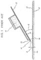
- Japanese Patent Laid-Open Publication No. 60-234851 teaches an ink jet printer causing liquid ink to fly due to an electric field formed between an ejection electrode and an opposite electrode facing the ejection electrode.
- the printer taught in this document includes a head positioned such that the surface of the opposite electrode and that of a lower plate forming part of the head make a preselected angle ⁇ of about 25 degrees to 40 degrees therebetween. Therefore, the direction of ink feed and the direction in which the weight of the ink acts are coincident, enhancing sharp response as to the replenishment of the ink.
- the problem with the above conventional printer is that the electric field for ejection cannot sufficiently center around an ejecting portion unless a voltage higher than an ordinary voltage is applied to the ejection electrode or unless the thickness of the lower plate is reduced.
- the voltage higher than an ordinary voltage is apt to bring about damage due to, e.g., leak, obstructing safety operation of the printer.
- the reduced thickness scheme it is necessary to reduce the thickness of the lower plate below the pitch of adjacent ejection electrodes. This, in turn, prevents the ejecting portions from being densely arranged in relation to the required hardness of the lower plate.
- An ink jet type head assembly of the present invention includes a base.
- a plurality of elongate ejection electrodes are formed on the base.
- An ink chamber has an opening facing one end of the ejection electrodes, and stores liquid ink containing charged toner particles on the base.
- One end of each ejection electrode is positioned on the base.
- An ink meniscus is formed between the end of the base where the above end of the ejection electrode is positioned and the opening of the ink chamber.
- An opposite electrode faces the ends of the ejection electrodes with the intermediary of a recording medium.
- the base is inclined about its end toward the ink chamber by a preselected angle with respect to a plane perpendicular to the lengthwise direction of the opposite electrode.
- the conventional printer has a head including a lower plate 53.
- An ejection electrode 56 is formed on the lower plate 53.
- An ink chamber 57 is formed on the ejection electrode 56 and stores liquid ink therein.
- An opening 55 is formed at one end portion of the ink chamber 57 and communicated to the chamber 57 by a passageway 59.
- An ink meniscus 61 is formed at the opening 55.
- An opposite electrode 52 is positioned on the imaginary extension of the ejection electrode 56 and connected to ground via a paper or similar recording medium 63.
- the outermost end of the ejection electrode 56 and the paper 63 are spaced from each other by a gap ⁇ .
- the head is positioned such that the surface of its lower plate 59 and that of the opposite electrode 52 make a preselected angle ⁇ of about 25 degrees to 40 degrees.
- the direction of ink feed is coincident with the direction in which the weight of the ink acts. This successfully enhances sharp response as to the replenishment of the ink.
- the above ink jet printer has the previously discussed problem because the actual point of ink ejection is spaced from the ejection electrode 56 by the thickness of the lower plate 53 intervening between the electrodes 56 and 52.
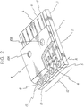
- the head assembly generally 1, includes a base 15 and a plurality of elongate ejection electrodes 6 arranged on the base 15 in parallel.
- An ink chamber 7 is formed on the base 15 and provided with an opening 12 facing one end of the ejection electrodes 6.
- the ink chamber 7 stores liquid ink containing charged toner particles.
- the ends of the ejection electrodes 6 facing the opening 12 are positioned on the base 15.
- Ink meniscuses 11 are formed between the end A (ejecting portion 5) of the base 15 and the opening 12, as illustrated.
- an opposite electrode 2 faces one end of the ejection electrodes 6 with the intermediary of a paper or similar recording medium 13.
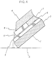
- the base 15 is inclined about its end A toward the ink chamber 7 by a preselected angle ⁇ with respect to a plane S perpendicular to the lengthwise direction L of the opposite electrode 2.
- the end A (ejecting portion 5) of the base 15 is closer to the opposite electrode 2 than the other portions of the head assembly 1.
- the end A of the base 15 where one end of the ejection electrodes 6 is positioned includes a corner.
- the base 15 is implemented as a layer of polyimide formed on the surface of the lower plate 3.
- the end A of the base 15 is located at a position slightly receded from the adjoining end of the lower plate 3.
- the ejection electrodes 6 are formed in parallel on the surface of the base 15 at a pitch corresponding to a desired recording density.
- the base 15 has its end rounded at positions corresponding to the ejection electrodes 6. Let the rounded portions be referred to as ejecting portions 5.
- a partition wall 8 is formed on each ejection electrode 6 at a position slightly receded from the end of the electrode 6.
- the adjacent walls 8 form therebetween a slit-like ink passage 9 fine enough to cause capillarity to occur. Such ink passages 9 play the role of the opening 12.
- the walls 8 each has a convex end, as illustrated.
- An upper plate 4 covers the surface of the base 15 where the ejection electrodes 6 are arranged, while forming a space corresponding to the height of the walls 8. This space is the ink chamber 7.
- the end of the upper plate 4 adjoining the walls 8 is located at a position slightly receded from the ends of the walls 8.
- the ink stored in the ink chamber 7 consists of a petroleum-based organic solvent (isoparaffin) and a charge control agent and fine colored particles of thermoplastic resin, i.e., toner particles dispersed in the solvent.
- the toner particles are apparently charged to the positive polarity by zeta potential beforehand.
- the ink chamber 7 is communicated to an ink reservoir, not shown, via a pump.
- the ink is constantly circulated through the ink chamber 7 via an inlet port 10A and an outlet port 10B while the inside of the chamber 7 is held at a constant pressure.
- the head assembly 1 is mounted on a carriage, not shown, movable back and forth. Means, not shown, for moving the carriage and the opposite electrode 2 are each affixed to a particular part of the body of an ink jet printer.
- the ink meniscus 11 is formed between each ejecting portion 5 and the end of the associated wall 8, as shown in FIG. 3. Because the inside of the ink chamber 7 is held at a constant pressure, the meniscus 11 remains in a stable condition. The end of each ejecting portion 5 is wetted with the ink. In this condition, a high-voltage pulse of the same polarity as the charge deposited on the toner particles is applied to any one of the ejection electrodes 6. The pulse causes the potential around the above electrode 6 to uniformly rise instantaneously.
- the toner particles around the electrode 6 are apt to fly away from the surface of the meniscus in the direction in which an electric field is formed between the electrode and the opposite electrode 2.
- the surface tension of the ink is greater than a Coulomb's force acting on the toner particles, preventing the toner particles from being ejected from the surface of the meniscus 11; that is, the particles simply float on the surface of the ink.
- the corner of the meniscus 11, i.e., the ejecting portion 5 the toner particles overcome the surface tension of the meniscus 11 and flies toward the opposite electrode 2 in the form of a drop 14.
- the voltage to be applied to the ejection electrode 6 in the form of a pulse should be a threshold voltage as to the ejection/non-ejection of the toner particles 14. If the voltage is lower than the threshold voltage, then the toner particles will not be ejected. If the former is higher than the latter, then unnecessary toner particles will be ejected from the portion other than the ejecting portion 5.
- the ejecting portion 5 should preferably be closest to the opposite electrode 6.
- the head assembly 1 is inclined such that the corner of each ejecting portion 5 is closest to the opposite electrode 2. Therefore, the electric field is most intense at the ejecting portion 5, i.e., centers around the portion 5. This insures stable ejection of the ink.
- the above configuration is physically stronger than a configuration having ejecting portions protruding from a lower plate, and can be readily maintained by wiping or similar cleaning means.
- the head assembly 1 may be positioned such that the ink chamber 7 is higher than the base 15 in the direction of gravity. Then, the toner particles will collect densely at the ink meniscus 11. This obviates the failure of ejection due to short toner particles and thereby further promotes stable ejection.
- an ink jet type head assembly includes a base carrying ejection electrodes thereon and inclined about its end toward an ink chamber with respect to a plane perpendicular to the lengthwise direction of an opposite electrode.
- a corner forming an ejecting portion is closest to the opposite electrode. Therefore, an electric field is most intense at the ejecting portion and centers around the ejecting portion stably. This insures stable ejection of ink.
- the head assembly is physically stronger than a conventional assembly having ejecting portions protruding from a lower plate, and can be readily maintained by wiping or similar cleaning means.
Landscapes
- Particle Formation And Scattering Control In Inkjet Printers (AREA)
- Printers Or Recording Devices Using Electromagnetic And Radiation Means (AREA)
Applications Claiming Priority (2)
| Application Number | Priority Date | Filing Date | Title |
|---|---|---|---|
| JP32168195A JP2783229B2 (ja) | 1995-12-11 | 1995-12-11 | インクジェット式ヘッド装置 |
| JP321681/95 | 1995-12-11 |
Publications (2)
| Publication Number | Publication Date |
|---|---|
| EP0779154A2 true EP0779154A2 (de) | 1997-06-18 |
| EP0779154A3 EP0779154A3 (de) | 1997-11-12 |
Family
ID=18135241
Family Applications (1)
| Application Number | Title | Priority Date | Filing Date |
|---|---|---|---|
| EP96119869A Withdrawn EP0779154A3 (de) | 1995-12-11 | 1996-12-11 | Tintenstrahlkopfanordnung |
Country Status (2)
| Country | Link |
|---|---|
| EP (1) | EP0779154A3 (de) |
| JP (1) | JP2783229B2 (de) |
Citations (1)
| Publication number | Priority date | Publication date | Assignee | Title |
|---|---|---|---|---|
| JPS60234851A (ja) | 1984-05-07 | 1985-11-21 | Tokyo Electric Co Ltd | インクジエツトプリンタ |
Family Cites Families (2)
| Publication number | Priority date | Publication date | Assignee | Title |
|---|---|---|---|---|
| JPS6110461A (ja) * | 1984-06-25 | 1986-01-17 | Nec Home Electronics Ltd | インクジエツトプリンタ |
| JPH06171135A (ja) * | 1992-12-04 | 1994-06-21 | Casio Comput Co Ltd | 静電記録装置 |
-
1995
- 1995-12-11 JP JP32168195A patent/JP2783229B2/ja not_active Expired - Fee Related
-
1996
- 1996-12-11 EP EP96119869A patent/EP0779154A3/de not_active Withdrawn
Patent Citations (1)
| Publication number | Priority date | Publication date | Assignee | Title |
|---|---|---|---|---|
| JPS60234851A (ja) | 1984-05-07 | 1985-11-21 | Tokyo Electric Co Ltd | インクジエツトプリンタ |
Also Published As
| Publication number | Publication date |
|---|---|
| EP0779154A3 (de) | 1997-11-12 |
| JPH09156111A (ja) | 1997-06-17 |
| JP2783229B2 (ja) | 1998-08-06 |
Similar Documents
| Publication | Publication Date | Title |
|---|---|---|
| US6158844A (en) | Ink-jet recording system using electrostatic force to expel ink | |
| US5754200A (en) | Ink jet type head assembly | |
| EP0779154A2 (de) | Tintenstrahlkopfanordnung | |
| EP0779152B1 (de) | Elektrostatischer Tintenstrahlaufzeichnungskopf | |
| US6412916B1 (en) | Ink jet printer | |
| US5969732A (en) | Electrostatic ink-jet recording device with control electrodes for selectively preventing ejection of toner | |
| EP0780229A1 (de) | Elektrostatischer Tintenstrahldruckkopf | |
| JP3706191B2 (ja) | 画像形成装置 | |
| JP2937961B2 (ja) | 静電式インクジェット記録装置 | |
| EP0882591B1 (de) | Elektrostatischer Tintenstrahldruckkopf mit einem mit konkaven und konvexen Teilen versehenen Kopfchip | |
| EP0778135B1 (de) | Elektrostatisches Tintenstrahlaufzeichnungsgerät | |
| JP2859242B2 (ja) | 静電式インクジェット記録ヘッド | |
| AU714245B2 (en) | Inkjet printer nozzle plate | |
| EP0847859B1 (de) | Elektrostatischer Tintenstrahldruckkopf | |
| JP3367840B2 (ja) | インクジェット記録装置 | |
| EP0836943A2 (de) | Elektrostatischer Tintenstrahldrucker und Tintenstrahlkopf | |
| JPH10151752A (ja) | 画像形成装置 | |
| EP0761442B1 (de) | Elektrostatischer Tintenstrahlaufzeichnungskopf mit mehreren Trennwänden in Tintenstrahlrichtung | |
| JP2783224B2 (ja) | インクジェット式ヘッド装置 | |
| JP2937955B2 (ja) | 静電式インクジェット記録ヘッド | |
| EP0764529B1 (de) | Elektrostatischer Tintenstrahlaufzeichnungskopf | |
| JPH0957976A (ja) | 静電式インクジェット記録装置 | |
| JP2004345313A (ja) | 液体吐出ヘッド | |
| JPH04201569A (ja) | 画像形成装置 | |
| JP2005081711A (ja) | 液滴吐出ヘッド |
Legal Events
| Date | Code | Title | Description |
|---|---|---|---|
| PUAI | Public reference made under article 153(3) epc to a published international application that has entered the european phase |
Free format text: ORIGINAL CODE: 0009012 |
|
| AK | Designated contracting states |
Kind code of ref document: A2 Designated state(s): DE FR GB |
|
| PUAL | Search report despatched |
Free format text: ORIGINAL CODE: 0009013 |
|
| AK | Designated contracting states |
Kind code of ref document: A3 Designated state(s): DE FR GB |
|
| 17P | Request for examination filed |
Effective date: 19971007 |
|
| 17Q | First examination report despatched |
Effective date: 19981123 |
|
| STAA | Information on the status of an ep patent application or granted ep patent |
Free format text: STATUS: THE APPLICATION IS DEEMED TO BE WITHDRAWN |
|
| 18D | Application deemed to be withdrawn |
Effective date: 19990407 |