EP0779559A1 - Wiederverwendbares Bildaufzeichnungsmaterial und Bild herstellende Vorrichtung sowie Methode zur Wiederverwendung - Google Patents
Wiederverwendbares Bildaufzeichnungsmaterial und Bild herstellende Vorrichtung sowie Methode zur Wiederverwendung Download PDFInfo
- Publication number
- EP0779559A1 EP0779559A1 EP19960119891 EP96119891A EP0779559A1 EP 0779559 A1 EP0779559 A1 EP 0779559A1 EP 19960119891 EP19960119891 EP 19960119891 EP 96119891 A EP96119891 A EP 96119891A EP 0779559 A1 EP0779559 A1 EP 0779559A1
- Authority
- EP
- European Patent Office
- Prior art keywords
- image
- recording material
- image recording
- imaging member
- film
- Prior art date
- Legal status (The legal status is an assumption and is not a legal conclusion. Google has not performed a legal analysis and makes no representation as to the accuracy of the status listed.)
- Withdrawn
Links
- 239000000463 material Substances 0.000 title claims abstract description 188
- 238000000034 method Methods 0.000 title claims abstract description 55
- 238000003384 imaging method Methods 0.000 claims abstract description 129
- 239000000758 substrate Substances 0.000 claims abstract description 26
- 239000002245 particle Substances 0.000 claims description 42
- 239000007787 solid Substances 0.000 claims description 31
- 229920005989 resin Polymers 0.000 claims description 24
- 239000011347 resin Substances 0.000 claims description 24
- 239000001993 wax Substances 0.000 claims description 17
- -1 polyethylene Polymers 0.000 claims description 15
- 239000004925 Acrylic resin Substances 0.000 claims description 10
- 229920000178 Acrylic resin Polymers 0.000 claims description 10
- 229920001225 polyester resin Polymers 0.000 claims description 10
- 239000004645 polyester resin Substances 0.000 claims description 10
- 229920006026 co-polymeric resin Polymers 0.000 claims description 8
- 239000004698 Polyethylene Substances 0.000 claims description 7
- 229920000573 polyethylene Polymers 0.000 claims description 7
- 239000004743 Polypropylene Substances 0.000 claims description 5
- 239000004203 carnauba wax Substances 0.000 claims description 5
- 235000013869 carnauba wax Nutrition 0.000 claims description 5
- 229920001155 polypropylene Polymers 0.000 claims description 5
- 229920002050 silicone resin Polymers 0.000 claims description 5
- 235000013871 bee wax Nutrition 0.000 claims description 4
- 239000012166 beeswax Substances 0.000 claims description 4
- 239000004200 microcrystalline wax Substances 0.000 claims description 4
- 235000019808 microcrystalline wax Nutrition 0.000 claims description 4
- 239000012170 montan wax Substances 0.000 claims description 4
- 239000012188 paraffin wax Substances 0.000 claims description 4
- 239000002609 medium Substances 0.000 description 33
- 239000010408 film Substances 0.000 description 32
- 239000010410 layer Substances 0.000 description 18
- 238000010438 heat treatment Methods 0.000 description 17
- 230000015572 biosynthetic process Effects 0.000 description 13
- LYCAIKOWRPUZTN-UHFFFAOYSA-N Ethylene glycol Chemical compound OCCO LYCAIKOWRPUZTN-UHFFFAOYSA-N 0.000 description 12
- 239000003921 oil Substances 0.000 description 11
- IISBACLAFKSPIT-UHFFFAOYSA-N bisphenol A Chemical compound C=1C=C(O)C=CC=1C(C)(C)C1=CC=C(O)C=C1 IISBACLAFKSPIT-UHFFFAOYSA-N 0.000 description 10
- 239000002904 solvent Substances 0.000 description 10
- 230000001070 adhesive effect Effects 0.000 description 9
- 230000000694 effects Effects 0.000 description 9
- 229920001296 polysiloxane Polymers 0.000 description 9
- 238000006243 chemical reaction Methods 0.000 description 8
- 239000003960 organic solvent Substances 0.000 description 8
- 239000012071 phase Substances 0.000 description 8
- 238000007639 printing Methods 0.000 description 8
- 239000004094 surface-active agent Substances 0.000 description 8
- 239000007864 aqueous solution Substances 0.000 description 7
- 239000003795 chemical substances by application Substances 0.000 description 7
- 239000003086 colorant Substances 0.000 description 7
- 229920000728 polyester Polymers 0.000 description 7
- XLYOFNOQVPJJNP-UHFFFAOYSA-N water Substances O XLYOFNOQVPJJNP-UHFFFAOYSA-N 0.000 description 7
- IJGRMHOSHXDMSA-UHFFFAOYSA-N Atomic nitrogen Chemical compound N#N IJGRMHOSHXDMSA-UHFFFAOYSA-N 0.000 description 6
- OKKJLVBELUTLKV-UHFFFAOYSA-N Methanol Chemical compound OC OKKJLVBELUTLKV-UHFFFAOYSA-N 0.000 description 6
- YXFVVABEGXRONW-UHFFFAOYSA-N Toluene Chemical compound CC1=CC=CC=C1 YXFVVABEGXRONW-UHFFFAOYSA-N 0.000 description 6
- 239000011230 binding agent Substances 0.000 description 6
- 230000000052 comparative effect Effects 0.000 description 6
- 238000001035 drying Methods 0.000 description 6
- 239000000243 solution Substances 0.000 description 6
- 239000000126 substance Substances 0.000 description 6
- 229920001577 copolymer Polymers 0.000 description 5
- 239000000178 monomer Substances 0.000 description 5
- 239000002699 waste material Substances 0.000 description 5
- 239000004793 Polystyrene Substances 0.000 description 4
- 235000010724 Wisteria floribunda Nutrition 0.000 description 4
- 239000008346 aqueous phase Substances 0.000 description 4
- 238000000576 coating method Methods 0.000 description 4
- 238000010586 diagram Methods 0.000 description 4
- WOZVHXUHUFLZGK-UHFFFAOYSA-N dimethyl terephthalate Chemical compound COC(=O)C1=CC=C(C(=O)OC)C=C1 WOZVHXUHUFLZGK-UHFFFAOYSA-N 0.000 description 4
- 150000002148 esters Chemical class 0.000 description 4
- 239000010419 fine particle Substances 0.000 description 4
- 239000012943 hotmelt Substances 0.000 description 4
- 239000000049 pigment Substances 0.000 description 4
- 229920006267 polyester film Polymers 0.000 description 4
- 229920002223 polystyrene Polymers 0.000 description 4
- 238000003756 stirring Methods 0.000 description 4
- XEKOWRVHYACXOJ-UHFFFAOYSA-N Ethyl acetate Chemical compound CCOC(C)=O XEKOWRVHYACXOJ-UHFFFAOYSA-N 0.000 description 3
- GOOHAUXETOMSMM-UHFFFAOYSA-N Propylene oxide Chemical compound CC1CO1 GOOHAUXETOMSMM-UHFFFAOYSA-N 0.000 description 3
- 238000004140 cleaning Methods 0.000 description 3
- XCJYREBRNVKWGJ-UHFFFAOYSA-N copper(II) phthalocyanine Chemical compound [Cu+2].C12=CC=CC=C2C(N=C2[N-]C(C3=CC=CC=C32)=N2)=NC1=NC([C]1C=CC=CC1=1)=NC=1N=C1[C]3C=CC=CC3=C2[N-]1 XCJYREBRNVKWGJ-UHFFFAOYSA-N 0.000 description 3
- 239000011521 glass Substances 0.000 description 3
- 230000009477 glass transition Effects 0.000 description 3
- 238000002844 melting Methods 0.000 description 3
- 239000000203 mixture Substances 0.000 description 3
- 229910052757 nitrogen Inorganic materials 0.000 description 3
- 229920001721 polyimide Polymers 0.000 description 3
- 229920000642 polymer Polymers 0.000 description 3
- 238000011084 recovery Methods 0.000 description 3
- 238000003786 synthesis reaction Methods 0.000 description 3
- CPHURRLSZSRQFS-UHFFFAOYSA-N 3-[4-[2-[4-(3-hydroxypropoxy)phenyl]propan-2-yl]phenoxy]propan-1-ol Chemical compound C=1C=C(OCCCO)C=CC=1C(C)(C)C1=CC=C(OCCCO)C=C1 CPHURRLSZSRQFS-UHFFFAOYSA-N 0.000 description 2
- 229920000298 Cellophane Polymers 0.000 description 2
- IAYPIBMASNFSPL-UHFFFAOYSA-N Ethylene oxide Chemical compound C1CO1 IAYPIBMASNFSPL-UHFFFAOYSA-N 0.000 description 2
- YCKRFDGAMUMZLT-UHFFFAOYSA-N Fluorine atom Chemical compound [F] YCKRFDGAMUMZLT-UHFFFAOYSA-N 0.000 description 2
- PEDCQBHIVMGVHV-UHFFFAOYSA-N Glycerine Chemical compound OCC(O)CO PEDCQBHIVMGVHV-UHFFFAOYSA-N 0.000 description 2
- VYPSYNLAJGMNEJ-UHFFFAOYSA-N Silicium dioxide Chemical compound O=[Si]=O VYPSYNLAJGMNEJ-UHFFFAOYSA-N 0.000 description 2
- XUIMIQQOPSSXEZ-UHFFFAOYSA-N Silicon Chemical compound [Si] XUIMIQQOPSSXEZ-UHFFFAOYSA-N 0.000 description 2
- 239000002253 acid Substances 0.000 description 2
- 239000002390 adhesive tape Substances 0.000 description 2
- 230000002411 adverse Effects 0.000 description 2
- 230000004075 alteration Effects 0.000 description 2
- 238000007611 bar coating method Methods 0.000 description 2
- YHWCPXVTRSHPNY-UHFFFAOYSA-N butan-1-olate;titanium(4+) Chemical compound [Ti+4].CCCC[O-].CCCC[O-].CCCC[O-].CCCC[O-] YHWCPXVTRSHPNY-UHFFFAOYSA-N 0.000 description 2
- 229910052799 carbon Inorganic materials 0.000 description 2
- 239000000919 ceramic Substances 0.000 description 2
- 239000012295 chemical reaction liquid Substances 0.000 description 2
- 239000000470 constituent Substances 0.000 description 2
- 239000003989 dielectric material Substances 0.000 description 2
- 239000004205 dimethyl polysiloxane Substances 0.000 description 2
- 235000013870 dimethyl polysiloxane Nutrition 0.000 description 2
- 238000007598 dipping method Methods 0.000 description 2
- 239000006185 dispersion Substances 0.000 description 2
- 239000005038 ethylene vinyl acetate Substances 0.000 description 2
- 239000000835 fiber Substances 0.000 description 2
- 239000000945 filler Substances 0.000 description 2
- 239000011737 fluorine Substances 0.000 description 2
- 229910052731 fluorine Inorganic materials 0.000 description 2
- 125000002887 hydroxy group Chemical group [H]O* 0.000 description 2
- 239000007788 liquid Substances 0.000 description 2
- 230000008018 melting Effects 0.000 description 2
- 229920000435 poly(dimethylsiloxane) Polymers 0.000 description 2
- 229920001200 poly(ethylene-vinyl acetate) Polymers 0.000 description 2
- 239000009719 polyimide resin Substances 0.000 description 2
- 238000006116 polymerization reaction Methods 0.000 description 2
- 238000001454 recorded image Methods 0.000 description 2
- 229910052710 silicon Inorganic materials 0.000 description 2
- 239000010703 silicon Substances 0.000 description 2
- 238000005507 spraying Methods 0.000 description 2
- 239000003381 stabilizer Substances 0.000 description 2
- 230000003068 static effect Effects 0.000 description 2
- 150000003443 succinic acid derivatives Chemical class 0.000 description 2
- 238000010558 suspension polymerization method Methods 0.000 description 2
- 238000010792 warming Methods 0.000 description 2
- RTTZISZSHSCFRH-UHFFFAOYSA-N 1,3-bis(isocyanatomethyl)benzene Chemical compound O=C=NCC1=CC=CC(CN=C=O)=C1 RTTZISZSHSCFRH-UHFFFAOYSA-N 0.000 description 1
- KPAPHODVWOVUJL-UHFFFAOYSA-N 1-benzofuran;1h-indene Chemical compound C1=CC=C2CC=CC2=C1.C1=CC=C2OC=CC2=C1 KPAPHODVWOVUJL-UHFFFAOYSA-N 0.000 description 1
- JQXYBDVZAUEPDL-UHFFFAOYSA-N 2-methylidene-5-phenylpent-4-enoic acid Chemical compound OC(=O)C(=C)CC=CC1=CC=CC=C1 JQXYBDVZAUEPDL-UHFFFAOYSA-N 0.000 description 1
- IICCLYANAQEHCI-UHFFFAOYSA-N 4,5,6,7-tetrachloro-3',6'-dihydroxy-2',4',5',7'-tetraiodospiro[2-benzofuran-3,9'-xanthene]-1-one Chemical compound O1C(=O)C(C(=C(Cl)C(Cl)=C2Cl)Cl)=C2C21C1=CC(I)=C(O)C(I)=C1OC1=C(I)C(O)=C(I)C=C21 IICCLYANAQEHCI-UHFFFAOYSA-N 0.000 description 1
- NIXOWILDQLNWCW-UHFFFAOYSA-M Acrylate Chemical compound [O-]C(=O)C=C NIXOWILDQLNWCW-UHFFFAOYSA-M 0.000 description 1
- 229910002012 Aerosil® Inorganic materials 0.000 description 1
- 101100091503 Arabidopsis thaliana ROS3 gene Proteins 0.000 description 1
- 229910014269 BS-H Inorganic materials 0.000 description 1
- DKPFZGUDAPQIHT-UHFFFAOYSA-N Butyl acetate Natural products CCCCOC(C)=O DKPFZGUDAPQIHT-UHFFFAOYSA-N 0.000 description 1
- OKTJSMMVPCPJKN-UHFFFAOYSA-N Carbon Chemical compound [C] OKTJSMMVPCPJKN-UHFFFAOYSA-N 0.000 description 1
- 229920002134 Carboxymethyl cellulose Polymers 0.000 description 1
- DGAQECJNVWCQMB-PUAWFVPOSA-M Ilexoside XXIX Chemical compound C[C@@H]1CC[C@@]2(CC[C@@]3(C(=CC[C@H]4[C@]3(CC[C@@H]5[C@@]4(CC[C@@H](C5(C)C)OS(=O)(=O)[O-])C)C)[C@@H]2[C@]1(C)O)C)C(=O)O[C@H]6[C@@H]([C@H]([C@@H]([C@H](O6)CO)O)O)O.[Na+] DGAQECJNVWCQMB-PUAWFVPOSA-M 0.000 description 1
- 206010034972 Photosensitivity reaction Diseases 0.000 description 1
- LGRFSURHDFAFJT-UHFFFAOYSA-N Phthalic anhydride Natural products C1=CC=C2C(=O)OC(=O)C2=C1 LGRFSURHDFAFJT-UHFFFAOYSA-N 0.000 description 1
- 239000004642 Polyimide Substances 0.000 description 1
- 101100235084 Saccharomyces cerevisiae (strain ATCC 204508 / S288c) LEM3 gene Proteins 0.000 description 1
- WYURNTSHIVDZCO-UHFFFAOYSA-N Tetrahydrofuran Chemical compound C1CCOC1 WYURNTSHIVDZCO-UHFFFAOYSA-N 0.000 description 1
- ZJCCRDAZUWHFQH-UHFFFAOYSA-N Trimethylolpropane Chemical compound CCC(CO)(CO)CO ZJCCRDAZUWHFQH-UHFFFAOYSA-N 0.000 description 1
- UKLDJPRMSDWDSL-UHFFFAOYSA-L [dibutyl(dodecanoyloxy)stannyl] dodecanoate Chemical compound CCCCCCCCCCCC(=O)O[Sn](CCCC)(CCCC)OC(=O)CCCCCCCCCCC UKLDJPRMSDWDSL-UHFFFAOYSA-L 0.000 description 1
- 238000010521 absorption reaction Methods 0.000 description 1
- 230000002378 acidificating effect Effects 0.000 description 1
- 239000000654 additive Substances 0.000 description 1
- 230000000996 additive effect Effects 0.000 description 1
- 239000000853 adhesive Substances 0.000 description 1
- 238000007605 air drying Methods 0.000 description 1
- 238000007754 air knife coating Methods 0.000 description 1
- 229910052782 aluminium Inorganic materials 0.000 description 1
- XAGFODPZIPBFFR-UHFFFAOYSA-N aluminium Chemical compound [Al] XAGFODPZIPBFFR-UHFFFAOYSA-N 0.000 description 1
- 229910021417 amorphous silicon Inorganic materials 0.000 description 1
- 239000002216 antistatic agent Substances 0.000 description 1
- 239000012736 aqueous medium Substances 0.000 description 1
- 238000001479 atomic absorption spectroscopy Methods 0.000 description 1
- IRERQBUNZFJFGC-UHFFFAOYSA-L azure blue Chemical compound [Na+].[Na+].[Na+].[Na+].[Na+].[Na+].[Na+].[Na+].[Al+3].[Al+3].[Al+3].[Al+3].[Al+3].[Al+3].[S-]S[S-].[O-][Si]([O-])([O-])[O-].[O-][Si]([O-])([O-])[O-].[O-][Si]([O-])([O-])[O-].[O-][Si]([O-])([O-])[O-].[O-][Si]([O-])([O-])[O-].[O-][Si]([O-])([O-])[O-] IRERQBUNZFJFGC-UHFFFAOYSA-L 0.000 description 1
- 239000011324 bead Substances 0.000 description 1
- JHIWVOJDXOSYLW-UHFFFAOYSA-N butyl 2,2-difluorocyclopropane-1-carboxylate Chemical compound CCCCOC(=O)C1CC1(F)F JHIWVOJDXOSYLW-UHFFFAOYSA-N 0.000 description 1
- 239000006229 carbon black Substances 0.000 description 1
- 239000011538 cleaning material Substances 0.000 description 1
- 239000011248 coating agent Substances 0.000 description 1
- 150000001875 compounds Chemical class 0.000 description 1
- 238000010276 construction Methods 0.000 description 1
- 238000001816 cooling Methods 0.000 description 1
- 230000010485 coping Effects 0.000 description 1
- 238000007766 curtain coating Methods 0.000 description 1
- 230000003247 decreasing effect Effects 0.000 description 1
- 230000007547 defect Effects 0.000 description 1
- 230000006866 deterioration Effects 0.000 description 1
- 230000002542 deteriorative effect Effects 0.000 description 1
- 239000012975 dibutyltin dilaurate Substances 0.000 description 1
- GYUVMLBYMPKZAZ-UHFFFAOYSA-N dimethyl naphthalene-2,6-dicarboxylate Chemical compound C1=C(C(=O)OC)C=CC2=CC(C(=O)OC)=CC=C21 GYUVMLBYMPKZAZ-UHFFFAOYSA-N 0.000 description 1
- 239000002270 dispersing agent Substances 0.000 description 1
- 238000004945 emulsification Methods 0.000 description 1
- 125000003700 epoxy group Chemical group 0.000 description 1
- 239000003822 epoxy resin Substances 0.000 description 1
- 238000011156 evaluation Methods 0.000 description 1
- 239000003925 fat Substances 0.000 description 1
- 150000002222 fluorine compounds Chemical class 0.000 description 1
- 235000011187 glycerol Nutrition 0.000 description 1
- 238000000227 grinding Methods 0.000 description 1
- LNEPOXFFQSENCJ-UHFFFAOYSA-N haloperidol Chemical compound C1CC(O)(C=2C=CC(Cl)=CC=2)CCN1CCCC(=O)C1=CC=C(F)C=C1 LNEPOXFFQSENCJ-UHFFFAOYSA-N 0.000 description 1
- 229920006015 heat resistant resin Polymers 0.000 description 1
- FUZZWVXGSFPDMH-UHFFFAOYSA-N hexanoic acid Chemical compound CCCCCC(O)=O FUZZWVXGSFPDMH-UHFFFAOYSA-N 0.000 description 1
- 230000006698 induction Effects 0.000 description 1
- 150000002500 ions Chemical class 0.000 description 1
- IQPQWNKOIGAROB-UHFFFAOYSA-N isocyanate group Chemical group [N-]=C=O IQPQWNKOIGAROB-UHFFFAOYSA-N 0.000 description 1
- BUZRAOJSFRKWPD-UHFFFAOYSA-N isocyanatosilane Chemical compound [SiH3]N=C=O BUZRAOJSFRKWPD-UHFFFAOYSA-N 0.000 description 1
- 238000004898 kneading Methods 0.000 description 1
- 239000006233 lamp black Substances 0.000 description 1
- MOUPNEIJQCETIW-UHFFFAOYSA-N lead chromate Chemical compound [Pb+2].[O-][Cr]([O-])(=O)=O MOUPNEIJQCETIW-UHFFFAOYSA-N 0.000 description 1
- 235000010187 litholrubine BK Nutrition 0.000 description 1
- 239000006247 magnetic powder Substances 0.000 description 1
- 238000012423 maintenance Methods 0.000 description 1
- 229940002712 malachite green oxalate Drugs 0.000 description 1
- 238000004519 manufacturing process Methods 0.000 description 1
- 229910052751 metal Inorganic materials 0.000 description 1
- 239000002184 metal Substances 0.000 description 1
- 229920003145 methacrylic acid copolymer Polymers 0.000 description 1
- 229940117841 methacrylic acid copolymer Drugs 0.000 description 1
- CXKWCBBOMKCUKX-UHFFFAOYSA-M methylene blue Chemical compound [Cl-].C1=CC(N(C)C)=CC2=[S+]C3=CC(N(C)C)=CC=C3N=C21 CXKWCBBOMKCUKX-UHFFFAOYSA-M 0.000 description 1
- 239000002480 mineral oil Substances 0.000 description 1
- 238000002156 mixing Methods 0.000 description 1
- TWNQGVIAIRXVLR-UHFFFAOYSA-N oxo(oxoalumanyloxy)alumane Chemical compound O=[Al]O[Al]=O TWNQGVIAIRXVLR-UHFFFAOYSA-N 0.000 description 1
- 239000010893 paper waste Substances 0.000 description 1
- 230000035515 penetration Effects 0.000 description 1
- 239000003208 petroleum Substances 0.000 description 1
- 230000036211 photosensitivity Effects 0.000 description 1
- 230000000704 physical effect Effects 0.000 description 1
- 229940099800 pigment red 48 Drugs 0.000 description 1
- 229920006122 polyamide resin Polymers 0.000 description 1
- 229920005668 polycarbonate resin Polymers 0.000 description 1
- 239000004431 polycarbonate resin Substances 0.000 description 1
- 229920000647 polyepoxide Polymers 0.000 description 1
- 229920005906 polyester polyol Polymers 0.000 description 1
- 229920000139 polyethylene terephthalate Polymers 0.000 description 1
- 239000005020 polyethylene terephthalate Substances 0.000 description 1
- 229920002689 polyvinyl acetate Polymers 0.000 description 1
- 239000011118 polyvinyl acetate Substances 0.000 description 1
- 239000000843 powder Substances 0.000 description 1
- 238000003825 pressing Methods 0.000 description 1
- 230000002265 prevention Effects 0.000 description 1
- 238000004537 pulping Methods 0.000 description 1
- 238000004445 quantitative analysis Methods 0.000 description 1
- 229940051201 quinoline yellow Drugs 0.000 description 1
- 235000012752 quinoline yellow Nutrition 0.000 description 1
- IZMJMCDDWKSTTK-UHFFFAOYSA-N quinoline yellow Chemical compound C1=CC=CC2=NC(C3C(C4=CC=CC=C4C3=O)=O)=CC=C21 IZMJMCDDWKSTTK-UHFFFAOYSA-N 0.000 description 1
- 239000004172 quinoline yellow Substances 0.000 description 1
- 239000002994 raw material Substances 0.000 description 1
- 229940081623 rose bengal Drugs 0.000 description 1
- 229930187593 rose bengal Natural products 0.000 description 1
- STRXNPAVPKGJQR-UHFFFAOYSA-N rose bengal A Natural products O1C(=O)C(C(=CC=C2Cl)Cl)=C2C21C1=CC(I)=C(O)C(I)=C1OC1=C(I)C(O)=C(I)C=C21 STRXNPAVPKGJQR-UHFFFAOYSA-N 0.000 description 1
- 238000007790 scraping Methods 0.000 description 1
- 238000007789 sealing Methods 0.000 description 1
- 239000003566 sealing material Substances 0.000 description 1
- 239000000377 silicon dioxide Substances 0.000 description 1
- 229920002379 silicone rubber Polymers 0.000 description 1
- 239000004945 silicone rubber Substances 0.000 description 1
- 229910052708 sodium Inorganic materials 0.000 description 1
- 239000011734 sodium Substances 0.000 description 1
- 238000004611 spectroscopical analysis Methods 0.000 description 1
- 238000003860 storage Methods 0.000 description 1
- 229920003048 styrene butadiene rubber Polymers 0.000 description 1
- 229920005792 styrene-acrylic resin Polymers 0.000 description 1
- 150000005846 sugar alcohols Polymers 0.000 description 1
- 239000002344 surface layer Substances 0.000 description 1
- 239000000454 talc Substances 0.000 description 1
- 229910052623 talc Inorganic materials 0.000 description 1
- 150000003503 terephthalic acid derivatives Chemical class 0.000 description 1
- 239000010409 thin film Substances 0.000 description 1
- 235000013799 ultramarine blue Nutrition 0.000 description 1
- 238000005406 washing Methods 0.000 description 1
- XOSXWYQMOYSSKB-LDKJGXKFSA-L water blue Chemical compound CC1=CC(/C(\C(C=C2)=CC=C2NC(C=C2)=CC=C2S([O-])(=O)=O)=C(\C=C2)/C=C/C\2=N\C(C=C2)=CC=C2S([O-])(=O)=O)=CC(S(O)(=O)=O)=C1N.[Na+].[Na+] XOSXWYQMOYSSKB-LDKJGXKFSA-L 0.000 description 1
- 238000009736 wetting Methods 0.000 description 1
- 239000002023 wood Substances 0.000 description 1
- 239000008096 xylene Substances 0.000 description 1
Images
Classifications
-
- G—PHYSICS
- G03—PHOTOGRAPHY; CINEMATOGRAPHY; ANALOGOUS TECHNIQUES USING WAVES OTHER THAN OPTICAL WAVES; ELECTROGRAPHY; HOLOGRAPHY
- G03G—ELECTROGRAPHY; ELECTROPHOTOGRAPHY; MAGNETOGRAPHY
- G03G7/00—Selection of materials for use in image-receiving members, i.e. for reversal by physical contact; Manufacture thereof
- G03G7/0006—Cover layers for image-receiving members; Strippable coversheets
- G03G7/002—Organic components thereof
- G03G7/0026—Organic components thereof being macromolecular
- G03G7/0046—Organic components thereof being macromolecular obtained otherwise than by reactions only involving carbon-to-carbon unsaturated bonds
-
- B—PERFORMING OPERATIONS; TRANSPORTING
- B41—PRINTING; LINING MACHINES; TYPEWRITERS; STAMPS
- B41M—PRINTING, DUPLICATING, MARKING, OR COPYING PROCESSES; COLOUR PRINTING
- B41M5/00—Duplicating or marking methods; Sheet materials for use therein
- B41M5/26—Thermography ; Marking by high energetic means, e.g. laser otherwise than by burning, and characterised by the material used
- B41M5/40—Thermography ; Marking by high energetic means, e.g. laser otherwise than by burning, and characterised by the material used characterised by the base backcoat, intermediate, or covering layers, e.g. for thermal transfer dye-donor or dye-receiver sheets; Heat, radiation filtering or absorbing means or layers; combined with other image registration layers or compositions; Special originals for reproduction by thermography
- B41M5/41—Base layers supports or substrates
-
- B—PERFORMING OPERATIONS; TRANSPORTING
- B41—PRINTING; LINING MACHINES; TYPEWRITERS; STAMPS
- B41M—PRINTING, DUPLICATING, MARKING, OR COPYING PROCESSES; COLOUR PRINTING
- B41M5/00—Duplicating or marking methods; Sheet materials for use therein
- B41M5/26—Thermography ; Marking by high energetic means, e.g. laser otherwise than by burning, and characterised by the material used
- B41M5/40—Thermography ; Marking by high energetic means, e.g. laser otherwise than by burning, and characterised by the material used characterised by the base backcoat, intermediate, or covering layers, e.g. for thermal transfer dye-donor or dye-receiver sheets; Heat, radiation filtering or absorbing means or layers; combined with other image registration layers or compositions; Special originals for reproduction by thermography
- B41M5/42—Intermediate, backcoat, or covering layers
- B41M5/44—Intermediate, backcoat, or covering layers characterised by the macromolecular compounds
- B41M5/443—Silicon-containing polymers, e.g. silicones, siloxanes
-
- G—PHYSICS
- G03—PHOTOGRAPHY; CINEMATOGRAPHY; ANALOGOUS TECHNIQUES USING WAVES OTHER THAN OPTICAL WAVES; ELECTROGRAPHY; HOLOGRAPHY
- G03G—ELECTROGRAPHY; ELECTROPHOTOGRAPHY; MAGNETOGRAPHY
- G03G7/00—Selection of materials for use in image-receiving members, i.e. for reversal by physical contact; Manufacture thereof
- G03G7/0006—Cover layers for image-receiving members; Strippable coversheets
- G03G7/002—Organic components thereof
- G03G7/0026—Organic components thereof being macromolecular
- G03G7/0033—Natural products or derivatives thereof, e.g. cellulose, proteins
-
- G—PHYSICS
- G03—PHOTOGRAPHY; CINEMATOGRAPHY; ANALOGOUS TECHNIQUES USING WAVES OTHER THAN OPTICAL WAVES; ELECTROGRAPHY; HOLOGRAPHY
- G03G—ELECTROGRAPHY; ELECTROPHOTOGRAPHY; MAGNETOGRAPHY
- G03G7/00—Selection of materials for use in image-receiving members, i.e. for reversal by physical contact; Manufacture thereof
- G03G7/0006—Cover layers for image-receiving members; Strippable coversheets
- G03G7/002—Organic components thereof
- G03G7/0026—Organic components thereof being macromolecular
- G03G7/004—Organic components thereof being macromolecular obtained by reactions only involving carbon-to-carbon unsaturated bonds
-
- Y—GENERAL TAGGING OF NEW TECHNOLOGICAL DEVELOPMENTS; GENERAL TAGGING OF CROSS-SECTIONAL TECHNOLOGIES SPANNING OVER SEVERAL SECTIONS OF THE IPC; TECHNICAL SUBJECTS COVERED BY FORMER USPC CROSS-REFERENCE ART COLLECTIONS [XRACs] AND DIGESTS
- Y10—TECHNICAL SUBJECTS COVERED BY FORMER USPC
- Y10S—TECHNICAL SUBJECTS COVERED BY FORMER USPC CROSS-REFERENCE ART COLLECTIONS [XRACs] AND DIGESTS
- Y10S428/00—Stock material or miscellaneous articles
- Y10S428/913—Material designed to be responsive to temperature, light, moisture
-
- Y—GENERAL TAGGING OF NEW TECHNOLOGICAL DEVELOPMENTS; GENERAL TAGGING OF CROSS-SECTIONAL TECHNOLOGIES SPANNING OVER SEVERAL SECTIONS OF THE IPC; TECHNICAL SUBJECTS COVERED BY FORMER USPC CROSS-REFERENCE ART COLLECTIONS [XRACs] AND DIGESTS
- Y10—TECHNICAL SUBJECTS COVERED BY FORMER USPC
- Y10S—TECHNICAL SUBJECTS COVERED BY FORMER USPC CROSS-REFERENCE ART COLLECTIONS [XRACs] AND DIGESTS
- Y10S428/00—Stock material or miscellaneous articles
- Y10S428/914—Transfer or decalcomania
-
- Y—GENERAL TAGGING OF NEW TECHNOLOGICAL DEVELOPMENTS; GENERAL TAGGING OF CROSS-SECTIONAL TECHNOLOGIES SPANNING OVER SEVERAL SECTIONS OF THE IPC; TECHNICAL SUBJECTS COVERED BY FORMER USPC CROSS-REFERENCE ART COLLECTIONS [XRACs] AND DIGESTS
- Y10—TECHNICAL SUBJECTS COVERED BY FORMER USPC
- Y10T—TECHNICAL SUBJECTS COVERED BY FORMER US CLASSIFICATION
- Y10T428/00—Stock material or miscellaneous articles
- Y10T428/24—Structurally defined web or sheet [e.g., overall dimension, etc.]
- Y10T428/24802—Discontinuous or differential coating, impregnation or bond [e.g., artwork, printing, retouched photograph, etc.]
- Y10T428/24851—Intermediate layer is discontinuous or differential
- Y10T428/24868—Translucent outer layer
- Y10T428/24876—Intermediate layer contains particulate material [e.g., pigment, etc.]
-
- Y—GENERAL TAGGING OF NEW TECHNOLOGICAL DEVELOPMENTS; GENERAL TAGGING OF CROSS-SECTIONAL TECHNOLOGIES SPANNING OVER SEVERAL SECTIONS OF THE IPC; TECHNICAL SUBJECTS COVERED BY FORMER USPC CROSS-REFERENCE ART COLLECTIONS [XRACs] AND DIGESTS
- Y10—TECHNICAL SUBJECTS COVERED BY FORMER USPC
- Y10T—TECHNICAL SUBJECTS COVERED BY FORMER US CLASSIFICATION
- Y10T428/00—Stock material or miscellaneous articles
- Y10T428/31504—Composite [nonstructural laminate]
- Y10T428/31652—Of asbestos
- Y10T428/31663—As siloxane, silicone or silane
Definitions
- the present invention relates to a reusable image recording material, an image forming device of the image recording material and a reusing method of the image recording material. More particularly, it relates to a device of removing an imaging member from the image recording material on which the imaging member is held by an image forming device using an electrophotographic or heat transfer system, and a reusable image recording material, capable of repeating image formation due to use of an imaging member and removal of an image in accordance with a method of reusing the image recording material utilizing an image forming device equipped with the device of removing the imaging member.
- the method of erasing the image is roughly classified into two methods. That is, there have been suggested one method of reducing adhesive properties between an imaging member and a substrate (paper) using a releasing liquid prepared by mixing water or a solvent with a surfactant and applying heat and pressure to peel off the imaging member from the substrate in a wet system, and another method of peeling due to an outer force (e.g. heat, pressure, mechanical force, etc.) without using water and a solvent, or previously forming an image having small adhesive properties and then peeling the imaging member due to heat, pressure, mechanical force and the like in a dry system.
- the following examples further illustrate the method of solving the above problems in detail.
- JP-A Japanese Patent Application Laid-Open
- 6-250569, 6-208318 and 6-250570 disclose a method of applying heat to an image recording material with being maintained an aqueous solution of a surfactant, hot-melting ink on the image recording material and peeling off ink using a releasing material.
- wetting between the image holding material and aqueous solution is important and it is necessary to penetrate the aqueous solution into an interface between the hot-melt ink and image holding material.
- the surface of the image holding material repels the aqueous solution, which does not penetrate and, therefore, an effect of improving the peelability between the imaging member and image holding material can not be obtained.
- the situation is the same in case of peeling off the image on the OHP sheet.
- a toner remained without being removed is accumulated on the image holding material and, therefore, the quality of the substrate (paper) deteriorates. Since a large amount of heat are required for drying the paper wetted with the aqueous solution, an amount of energy consumed becomes larger and a running cost becomes larger.
- JP-A Japanese Patent Application Laid-Open (JP-A) Nos. 1-101576 and 1-101577 direct to a method of dissolving and removing a toner resin by applying or dipping a soluble solvent to the image recording material.
- JP-A Japanese Patent Application Laid-Open
- JP-A No. 4-300395 discloses a method of adhering a solvent to an image recording material using dipping, spraying or applying means, dissolving a toner in the image recording material and removing the dissolved toner using washing, sucking or adsorbing means to reuse the image recording material.
- These methods make it possible to remove the imaging member on the image recording material but have a problem such as influence of use of an organic solvent on safety and environment, enormous quantity of energy required for removing the solvent and curling of the paper after drying. Furthermore, there arose a new problem that the toner dissolved in the solvent is adhered again to the image recording material.
- the quality of the image holding material reused is not sufficient. Any way, an enormous quantity of energy is required for drying the releasing agent used to remove or erase the imaging member in a wet system. Since an additive (e.g. surfactant, etc.) contained in the releasing agent is accumulated in the image holding material by using repeatedly, an adverse influence is exerted on repeated image formation.
- an additive e.g. surfactant, etc.
- JP-A Japanese Patent Application Laid-Open
- JP-A Japanese Patent Application Laid-Open
- 4-67043 suggest an erasing method comprising applying a silicone sealing material on a coated paper in a small thickness, drying the coated material to form a paper (erasable paper) whose surface is releasing-treated, printing on this paper, coating the surface of the print with a hot-melt material (cleaning material) in the hot-melt state for the purpose of cleaning, cooling and then removing a print (e.g. letter image, etc.) together with the hot-melt material.
- This method had the following drawbacks.
- JP-A Japanese Patent Application Laid-Open (JP-A) No. 6-219068 discloses a reusable recording medium obtained by applying a thermal modified material (e.g.
- This recording medium has the same drawback as that of the image recording material subjected to the releasing treatment, and it is necessary to form the part, which is not subjected to the releasing treatment, by previously sealing both ends of the recording medium so as to obtain traveling properties of the recording medium.
- the releasing material is formed on the recording material by dissolving the releasing material in an organic solvent and applying the resulting solution to a substrate or impregnating the substrate with the solution. Therefore, the releasing material is formed on the total surface of the recording material.
- the traveling properties and conveying properties of the recording material in the image forming device are serious problems and, furthermore, the writing properties are also serious problems because the releasing material is present even at the part where no image is present. Since the releasing material is generally expensive, a large amount of the releasing material is required in the applying or impregnating method. A low utilization efficiency leads to an increase in cost.
- the present invention has been accomplished for the purpose of solving the problems described above in the prior arts under these circumstances.
- an object of the present invention is to provide an image recording paper which makes it possible to promptly reuse a waste paper by an individual without relying on technical vendors and damaging the image of a plain paper.
- Another object of the present invention is to provide a reusable image recording paper which makes it possible to remove an imaging member with maintaining good fixing properties of the imaging member to the image recording paper without injuring the paper surface.
- a still another object of the present invention is to provide an image forming device using an electrophotographic or heat transfer system (device for producing an image recording material) for obtaining a reusable image recording paper.
- a further object of the present invention is to provide an image recording paper which makes it possible to easily reuse not only a monochromic image but also a color image, obtained by full solid printing, using such an image forming device.
- a still further object of the present invention is to provide an image recording paper which makes it possible to solve a problem about paper passing properties in the device, wherein the material having a peelability has no transfer to the other material.
- Another object of the present invention is to provide an image recording paper which makes it possible that, when using the electrophotographic system image forming device, a normal acidic paper has a problem of image quality defects caused by transfer of fillers (e.g. talc, etc.) to the surface of the photosensitive material, however, transfer of the fillers is solved by fixing together with the material having a peelability on the surface of the recording paper.
- a further object of the present invention is to provide an image recording paper capable of sufficiently coping with imaging members (e.g.
- a still further object of the present invention is to provide a method for reusing an image recording material, which makes it possible that an image recording material for reusing the image is not previously prepared but a plain paper is used in case of a normal image recording, and the plain paper is converted into a reusable recording material when reuse is required, i.e. when it is necessary to erase a record because an image recording material is temporarily required.
- an image recording material can be made on the required position at the required time by previously forming an imaging member containing a releasing material on the total surface or required position of an recording medium for image formation (e.g. plain paper recording paper, converted paper, polyester film used for OHP, etc.) as a thin film having good peelability using an image forming device. It has also been found that the image recording material thus obtained makes it possible to make a reusable recording medium without damaging writing properties on the recording material and to simultaneously satisfy the fixing properties and peelability of the imaging member. The image recording material also makes it possible to easily reuse not only a monochromic image but also a color image, obtained by full solid printing. Thus, the present invention has been accomplished.
- an imaging member containing a releasing material on the total surface or required position of an recording medium for image formation (e.g. plain paper recording paper, converted paper, polyester film used for OHP, etc.) as a thin film having good peelability using an image forming device.
- an imaging medium for image formation e.g. plain paper recording paper, converted paper
- the reusable image recording material of the present invention comprises a substrate, and a film which is comprised of an imaging member containing a releasing material, the film being formed on the surface of the substrate.
- the image forming device of the present invention is characterized in that the image forming device utilizes an electrophotographic system or a heat transfer system, and that a film comprising an imaging member containing a releasing material is formed on a substrate.
- the method for reusing an image recording material of the present invention comprises the steps of: forming a film comprising an imaging member containing a releasing material on the surface of a substrate; forming an image on the film; and bringing the image and a transfer medium into close contact and applying heat and pressure to transfer the image to the transfer medium.
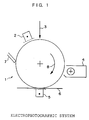
- Fig. 1 is a schematic diagram illustrating the electrophotographic system image forming device in the present invention.
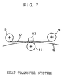
- Fig. 2 is a schematic diagram illustrating the heat transfer system image forming device in the present invention.
- a reusable image recording medium by containing a releasing material such as fluorine compounds, silicone compounds, synthetic waxes (e.g. polyethylene, polypropylene, etc.) and natural waxes (e.g. carnauba wax, etc.) in an imaging member; making the imaging member on the surface of a recording medium (e.g. plain paper recording paper, converted paper, OHP, etc.) using an image forming device to form a film having a peelability on the recording medium; and transferring an image recorded on the film to a transfer medium, which is opposed to the recording medium, using heat, pressure, etc.
- a releasing material such as fluorine compounds, silicone compounds, synthetic waxes (e.g. polyethylene, polypropylene, etc.) and natural waxes (e.g. carnauba wax, etc.) in an imaging member
- a recording medium e.g. plain paper recording paper, converted paper, OHP, etc.
- the fixing properties and recording properties of the image recording medium can stand comparison with a conventional image recording medium. Not only the peelability of an image formed on the upper layer is satisfied by previously forming a releasing layer (peeling layer) using the imaging member containing the releasing material, but also the affinity between the imaging member and image recording material is improved by containing the same material as that of the image recording material (e.g. toner, ink, etc.) as a constituent component of the imaging member.
- the same material as that of the image recording material e.g. toner, ink, etc.
- the surface of the releasing layer of the imaging member has a proper unevenness and, therefore, an "anchor effect" due to penetration of the image recording material (e.g. toner, transfer ink, etc.) formed on the upper layer into the unevenness and a cohesive force of the imaging member itself exhibit sufficient fixing properties of the image recording material.
- the cohesive force is lowered by heating so that it can flow or melt.
- the adhesive properties between the imaging member and recording medium are lowered by the releasing layer (peeling layer) formed on the under layer and, at the same time, the adhesive properties between the imaging member and opposite transfer medium are enhanced. Therefore, it is believed that the toner or transfer ink is peeled off from the recording medium by transferring the toner or transfer ink to the opposite transfer medium.
- Examples of the recording medium which can be used in the present invention include, for example, plain paper and recording paper used generally for electrophotographic recording, heat transfer paper utilized for heat transfer recording, converted paper used for high-grade printing, slight coated paper, transparent resin (e.g. polyester film, styrene-acrylic resin, etc.) used for OHP and the like.
- plain paper and recording paper used generally for electrophotographic recording
- heat transfer paper utilized for heat transfer recording converted paper used for high-grade printing
- slight coated paper e.g. polyester film, styrene-acrylic resin, etc.
- the imaging member used in the present invention contains a releasing material and a binder resin, and is preferably used in the particle form in view of ease of handling and image formation.
- the releasing material is at least one material selected from the group consisting of fluororesins; silicone resins; copolymer resins of the above resins; copolymer resins of the above resins and resin selected from an acrylic resin and a polyester resin; low molecular weight synthetic waxes selected from polyethylene and polypropylene; and natural waxes selected from the group consisting of carnauba wax, beeswax, montan wax, paraffin wax and microcrystalline wax.
- the binder resin used in combination with them include, for example, acrylic resins (e.g.
- styrene-methacrylic acid copolymer. etc. used generally as an imaging resin, polyester resins, polyamide resins, polyimide resins, epoxy resins, polycarbonate resins and the like.
- the method of forming the binder resin containing these releasing materials into fine particles for example, there can be used a method of making fine particles by kneading, grinding and classifying and a known method of dispersing an oil phase containing an imaging member in an aqueous medium, followed by granulating. Examples thereof include suspension polymerization method described in Japanese Patent Application Publication (JP-B) No. 36-10231, method described in Japanese Patent Application Publication (JP-B) No. 61-28688 and the like.
- the suspension polymerization method is a method of dissolving or dispersing a polymeric monomer and a toner material (e.g. colorant, releasing agent. etc.) to form a monomer composition; thereafter dispersing this monomer composition into an aqueous phase containing a dispersion stabilizer using a suitable stirrer; and simultaneously conducting the polymerization reaction to obtain an imaging member having a desired particle size.
- a toner material e.g. colorant, releasing agent. etc.
- 61-28688 is a method comprising dissolving or dispersing an imaging member into an organic solvent, which hardly dissolve in water, to form an oil phase; dispersing this oil phase into an aqueous phase containing a dispersion stabilizer; and removing the solvent to make image forming fine particles.
- a method comprising adding a new monomer to a dispersion-stabilized oil phase to cause the polymerization reaction at the interface of the oil phase; followed by capsulating to prepare an imaging member.
- the method may be any method capable of granulating an imaging member comprising the releasing material and binder resin, and is not limited to the above methods.
- the releasing material is preferably contained in an amount of 10 to 90% by weight in the solid part of the imaging member, more preferably 30 to 70% by weight, and most preferably 40 to 60% by weight, in view of the effect.
- the amount of the releasing material contained in the imaging member is less than 10% by weight, the image formed on the upper layer is not sufficiently peeled off.
- it exceeds 90% by weight it becomes difficult to form as the imaging member and image characteristics (e.g. maintenance, image stability, etc.) in the image forming device deteriorate drastically. Since the adhesive properties between the imaging member and image recording medium also deteriorate, a film forming capability of the releasing layer forming material also reduces.
- a colorant may be formulated into the imaging member for the purpose of distinguishing it from the plain paper recording medium, using to prevent alteration of an image or utilizing it as the reusable imaging member.
- the colorant formulated include carbon black, nigrosine, aniline blue, chrome yellow, ultramarine blue, Du Pont oil red, quinoline yellow, methylene blue chloride, phthalocyanine blue, malachite green oxalate, lamp black, rose bengal, C.I. pigment red 48:1, C.I. pigment red 122, C.I. pigment red 57:1, C.I. pigment yellow 97, C.I. pigment yellow 12, C.I. pigment blue 15:1, C.I. pigment blue 15:3, magnetic powder and the like.
- a reusable image recording material comprising a film which is comprised of an imaging member containing a releasing material, using a heat transfer film wherein the imaging member in the present invention is formed on a film.
- an ink layer of the transfer film can be obtained by dispersing or dissolving the imaging member into water or an organic solvent, or melting the imaging member itself with heating to form a liquid, and then applying resultant material on a substrate such as polyester film.
- the surface which is directly in contact with the thermal head, may be coated with a heat-resistant resin (e.g. silicone resin, fluorine resin, polyimide resin, etc.) and a high-temperature non-adhesive surfactant, as a heat-resistant layer.
- a heat-resistant resin e.g. silicone resin, fluorine resin, polyimide resin, etc.
- the imaging member containing the releasing material of the present invention can also be used as the heat-resistant layer.
- colorants, solid waxes, binder resins, tackifiers, antistatic agents, pigment dispersants, fats and oils (mineral oils), etc. as the ink layer may be added.
- the imaging member is preferably white or transparent in order to utilize as the image forming medium.
- a colorant may be formulated into the imaging member for the purpose of distinguishing it from the plain paper recording medium, using to prevent alteration of an image or utilizing it as the reusable imaging member.
- the colorants can be used the above colorants of the imaging member.
- the releasing material is contained in the imaging member and, therefore, a solid wax added for the same purpose is not required furthermore.
- a solid wax which is similar to the releasing material in the present invention, for the purpose of improving performances of the transfer film, e.g. adjustment of a melting point due to the addition of the solid wax.
- the binder resin for example, there can be used EVA (ethylene-vinyl acetate copolymer), polystyrene, polyester, polyvinyl acetate, styrene-butadiene copolymer and the like.
- the tackifier for example, there can be used petroleum resins, polypentene, coumarone-indene resins, rosins and the like.
- the application method in case of forming these films for example, there can be used methods which are normally used, such as blade coating method, wire bar coating method, spray coating method, bead coating method, air knife coating method, curtain coating method, rod bar coating method, roll coating method and the like.
- thermodrying the peelability to the imaging member is further improved when thermodrying is conducted.
- methods which are normally used such as method of putting in an oven or passing through the oven, method of bringing it into contact with a heat roller and the like.
- the step of forming a film on the surface of a substrate and step of forming an image on the film are conducted by transferring the film and developed image to the image recording material.
- the step of bringing the image on the image recording material and transfer medium into close contact and applying heat and pressure to transfer the image to the transfer medium is a step of removing the imaging member from the image recording material wherein the image has been formed.
- this method is preferably the same as that used for forming the imaging member on the image recording paper in view of the principle.
- an image is formed by fixing the imaging member on the paper utilizing heat.
- the imaging member on the paper is molten by heating again the image, which was once fixed, thereby easily removing the imaging member from the paper. Therefore, if the fixing device in the image forming device can be also used as a peeling device, the image forming device itself can be an image removing device without preparing a special device, separately, and open spaces can be effectively used in comparison with the case of providing the peeling device, separately.
- auxiliary means for removing the imaging member there can be used a method of impregnating the image recording paper with an organic solvent for dissolving the imaging member or, an aqueous solution or an organic solvent containing a surfactant for decreasing bonding between paper fibers and imaging member, or an organic solvent, and a method of removing the imaging member utilizing a physical action (e.g. ultrasonic vibration, etc.) together with these methods.
- a physical action e.g. ultrasonic vibration, etc.
- the step of forming the film is applied to a portion of a substrate at which portion an image is formed, and heat and pressure can be applied to only the portion and the imaging member can be removed from the portion.
- Fig. 1 is a schematic diagram illustrating the electrophotographic system image forming device.
- a photosensitive material 1 is driven in the direction of the arrow 8 and a cleaner device 7, a charging device 2, latent image forming means 3, an developing device for imaging member 4, a transfer device 5 and a recording paper 6 are arranged in order on the periphery of the photosensitive material.
- the photosensitive material 1 which is used as an image carrier for example, OPC is used in the embodiment of the present invention.
- a known photosensitive material e.g. Se, a-Si, etc.
- a dielectric material having no photosensitivity e.g. polyethylene terephthalate, aluminum oxide, etc.
- the charging device 2 for uniformly charging the surface of the image carrier 1 for example, scolotron is used in the embodiment of the present invention and the surface of the image carrier 1 is uniformly charged to negative (-600 V).
- known roller charging device and brush charging device can be used as the charging device.
- the latent image forming means 3 for example, there can be used light writing means represented by laser ROS, means for writing by controlling an ion flow and the like.
- the image carrier 1 is a photosensitive material.
- it is a dielectric material.
- the developing device 4 for imaging particles containing the releasing material may be any one which comprises known powder developing means. In the embodiment of the present invention, a two-component magnetic brush developing device is used.
- the transfer device 5 for transferring the image there can be used the same charging device 2 except that a polarity is different. Formation of the image in this construction is conducted as follows. That is, the photosensitive material 1 is driven (circumferential rate: 100 mm/second) in the direction of the arrow 8 using driving means (not shown). Then, the surface of the photosensitive material 1 is charged to -600 V using a scolotron charging device 2 and a static latent image is formed using a laser ROS3. The static latent image is developed using the developing device 4 of image developing means, and then transferred to the recording paper 6 driven by the driving means (not shown) using known transfer means.
- the imaging particles remained on the photosensitive material 1 is removed using the cleaner device 7.
- a system using a cleaner is assumed in the embodiment of the present invention, the present invention can be accomplished by a cleanerless system even if cleanerless is accomplished in any form.
- cleaning means e.g. brash, cleaning roll, mag brush roll, etc.
- the recording paper is fixed using fixing means (not shown) to obtain an image on the recording paper. That is, an image recording paper having a film comprising the imaging member containing the releasing material is obtained on the surface of the recording paper.
- Fig. 2 is a schematic diagram illustrating the heat transfer system image forming device. All constituent parts are arranged as follows. That is, an ink sheet 12 is conveyed or taken up using a driving roll 9 and the ink sheet 12 and a recording paper 10 are heated and pressurized using a press roll 11 and a heating device 13 and, further, an ink image is recorded on the recording paper.
- the driving roll 9 for feeding or taking up the ink sheet for image formation 12 is arranged as shown in Fig. 2.
- the ink sheet 12 is provided with a releasing layer so as to easily peel off ink from a heat transfer film such as polyester, polyimide and the like, and ink for image formation containing the releasing material is applied on the releasing layer to form an ink sheet.
- the recording paper 10 may be any one which is generally used in the heat transfer system, such as plain paper, surface coated paper, OHP paper and the like.
- the press roll 11 for pressing the recording paper 10 and ink sheet 12 is arranged.
- the heating device 13 a ceramic heater is used in the embodiment of the present invention.
- there can be used heating devices having known heating means such as heat roll heating, planar heating unit, magnetic induction heating and the like.
- the ink sheet 12 and recording paper 10 are moved in the same direction and interposed between the press roll 11 and heating device (ceramic heater) 13, where they are heated and pressurized, thereby transferring ink on the ink sheet to the recording paper to record an image on the recording paper. That is, there can be obtained an image recording paper having a film comprising ink for forming image, which containing a releasing material, on the surface of the recording paper.
- Examples and Comparative Examples further illustrate the present invention in detail but are not to be construed to limit the scope thereof.
- "parts" are by weight unless otherwise stated.
- the electrophotographic system was used for the image forming device.
- the heat transfer system was used for the image forming device.
- Silica 1%, R972 manufactured by Nihon Aerosil Co.
- Acolor 635 manufactured by Fuji Xerox Co.
- the fixing properties of the imaging member were evaluated by using, as an index, a ratio of an image density before peeling to that after peeling (hereinafter abbreviated to an "OD ratio") determined by adhering a commercially available cellophane adhesive tape having a width of 18 mm (cellophane tape, manufactured by Nichiban Co., Ltd) on the solid image part having a density of about 1.8 (density of the image fixed by the above electrophotographic system image forming device shown in Fig.
- OD ratio a ratio of an image density before peeling to that after peeling
- the imaging member 1 is measured by using a densitometer X-Rite 938 (manufactured by X-Rite Co.)) at a linear pressure of 300 g/cm and then peeling the adhesive tape at a rate of 10 mm/second (OD ratio: image density after peeling/image density before peeling). It is necessary that the imaging member has fixing properties (OD ratio: not less than 0.8) as an electrophotographic recording medium.
- a heat roller having a silicone rubber surface layer in a fixing device of the above image forming device was replaced by a heat roller whose surface is coated with an aluminum anodic oxidized film and, furthermore, a metal blade for scraping the imaging particles from the paper was mounted on the heat roller. Only by passing the image recorded material, on which the image has been recorded, through the fixing device of the above device, the imaging particles could be removed to reuse the image recording paper. After removing the imaging particles, the residual amount of them on the reused paper was evaluated by using the OD ratio as the index according to the same manner as that of the evaluation of the fixing properties of the imaging particles.
- the OD ratio of not more than 0.08 is preferred.
- the fixing properties of the image recording onto the paper and the imaging particles after removal of the image on the paper were repeated ten times, and the residual amount of the imaging particles on the reused paper after removal were evaluated and the repeating stability was confirmed.
- the results of the respective Examples and Comparative Examples described hereinafter are shown in Table 1.
- imaging particles were prepared (content of a releasing material in imaging particles: 5% by weight). According to the same manner as that described in Example 1, a solid image was formed on a Xerox paper using the resulting imaging particles. A color image including letters and solid images was fixed on the image recording material using Acolor 635. According to the same manner as that described in Example 1, the fixing properties, peelabilities and writing properties of the image on the image recording material were evaluated.
- dimethyl 2,6-naphthalenedicarboxylate (73.2 g, 0.3 mol), dimethyl terephthalate (135.8 g, 0.7 mol), 2,2-di(4-hydroxypropoxyphenyl)propane (206.4 g, 0.6 mol), ethylene glycol (124.0 g, 2.0 mol), tetrabutyl titanate (0.27 g. 0.8 mmol) and epoxy group-containing dimethyl polysiloxane (111.4 g, 0.2 mol) represented by the following [Chemical formula 1] were charged. Then, the demethanolation reaction was conducted by heating at 160 to 170°C using a mantle heater under a nitrogen flow for 6 hours. In that case, an amount of methanol distilled off in an ester adapter was 62.1 g.
- the deethylene-glycolation reaction was conducted at 220 to 240°C under reduced pressure of 20 mmHg for 3 hours.
- An amount of ethylene glycol distilled off was 71. 2 g.
- the resulting polymer was cooled to room temperature to obtain 386.9 g of a pale brown translucent solid.
- a weight-average molecular weight (calibrated by the standard polystyrene) in GPC was 20,000 and a glass transition point determined by DSC (differential scanning calorimeter) was 66°C and, further, a softening point determined by the ring and ball method was 115°C.
- a hydroxyl group value (JIS K 0070) was 25.7 mg KOH/g.
- the corresponding monomer was composed of a polycarboxylic acid of a molar ratio represented by the following (Chemical formula 2) and a polyhydric alcohol of a molar ratio represented by the following (Chemical formula 3).
- the quantitative analysis of dimethyl polysiloxane was conducted by atomic-absorption spectroscopy. As a result, 19.9% by weight of the resulting polymer was dimethyl siloxane.
- polyester polyol (150 g) obtained in the above Synthesis Example and toluene (300 g) were charged, and then dissolved at 60°C. Then, dibutyltin dilaurate (0.17 g) and isocyanate group-containing organopolysiloxane (17.8 g) represented by the following (Chemical formula 4) were added, and the mixture was reacted at 70°C under a nitrogen flow for 5 hours. IR spectroscopic analysis of the resulting reaction liquid was conducted.
- a copolymer (FX-3330, manufactured by Sumitomo 3M Co., ethyl acetate solution having a solid content ratio of 30%) of a fluororesin and an acrylic resin, 15 parts of a polyester resin (Tg: 66°C, Tm: 105°C) comprising a propylene oxide adduct of bisphenol A, an ethylene oxide adduct of bisphenol A and a succinic acid derivative, 1.5 parts of the above polyester-silicone copolymer, 0.9 parts of silyl isocyanate (Orgatix SI-310, manufactured by Matsumoto Seiyaku Co.) and 3 parts of an adduct (Takenate D-110N, manufactured by Takeda Chemical Industries, Ltd.) of xylene diisocyanate (3 mol) and trimethylolpropane (1 mol) were mixed with stirring to prepare an oil phase.
- a polyester resin Tg: 66°C, Tm: 105°C
- Example 2 According to the same manner as that described in Example 2 except for changing to 70 parts of a copolymer (FC-725, manufactured by Sumitomo 3M Ltd., butyl acetate solution having a solid content ratio of 30% by weight) of a fluororesin and an acrylic resin, 9 parts of a polyester resin (Tg: 66°C, Tm: 105°C) comprising a propylene oxide adduct of bisphenol A, an ethylene oxide adduct of bisphenol A and a succinic acid derivative and 2.1 parts of the above polyester-silicone copolymer, imaging particles (content of a releasing material in imaging particles: 90% by weight) were prepared.
- a copolymer FC-725, manufactured by Sumitomo 3M Ltd., butyl acetate solution having a solid content ratio of 30% by weight
- 9 parts of a polyester resin Tg: 66°C, Tm: 105°C
- imaging particles content of a releasing material in imaging particles: 90% by
- Example 1 an image recording material whose total surface is coated with imaging particles was prepared using the resulting imaging particles. According to the same manner as that described in Example 1, an image was recorded on this image recording material, and fixing properties and peelabilities thereof were evaluated.
- a trial of preparing imaging particles was made using the same materials as those of Example 2 except for using 100 parts of a copolymer (FX-3330, manufactured by Sumitomo 3M Ltd.) of a fluororesin and an acrylic resin and using no polyester resin of Example 2 under the same conditions.
- a copolymer FX-3330, manufactured by Sumitomo 3M Ltd.
- formation of particles (emulsification) in the solution could not conducted using only a releasing material.
- imaging particles could not be prepared.
- imaging particles (content of a releasing material in imaging particles: 70% by weight) were prepared. According to the same manner as that described in Example 1, an image recording material whose total surface is coated with imaging particles was prepared using the resulting imaging particles. According to the same manner as that described in Example 1, an image was recorded on this image recording material, and fixing properties and peelabilities thereof were evaluated.
- imaging particles (content of a releasing material in imaging particles: 70% by weight) were prepared. According to the same manner as that described in Example 1, an image recording material whose total surface is coated with imaging particles was prepared using the resulting imaging particles. According to the same manner as that described in Example 1, an image was recorded on this image recording material and fixing properties and peelabilities thereof were evaluated.
- the imaging member of Example 2 was diluted with THF (tetrahydrofuran) so that the concentration of the solid content became 10% and a polyester film was coated with the resulting solution using a wire bar, followed by drying at the temperature of 100°C to prepare a transfer film having an ink layer (thickness: about 3 ⁇ m) containing a releasing material.
- This transfer film was mounted to a heat transfer device FNP-300 manufactured by Matsushita Electric Industrial Co., Ltd. (heat transfer system image forming device shown in Fig. 2) and a full solid image was printed on a J paper for Xerox (A4 size). The resultant was used as a reusable image recording material. A color image including letters and solid images was fixed on this image recording material using Acolor 635.
- the fixing properties and peelabilities of the imaging member were evaluated according to the same manner as that described in Example 1.
- Example 4 According to the same manner as that described in Example 6 except for using the imaging member of Example 4, a transfer film was prepared. This transfer film was mounted to a heat transfer device FNP-300 manufactured by Matsushita Electric Industrial Co., Ltd. and a full solid image was printed on a J paper for Xerox (A4 size). The resultant was used as a reusable image recording material. A color image including letters and solid images was fixed on this image recording material using Acolor 635.
- the fixing properties and peelabilities of the imaging member were evaluated according to the same manner as that described in Example 1.
- a monochromic image was printed on the image recording material obtained in Example 7 using a heat transfer device FNP-300 manufactured by Matsushita Electric Industrial Co., Ltd..
- the fixing properties and peelabilities of the imaging member were evaluated according to the same manner as that described in Example 1.
- Example 2 The same image as that, which is finally printed, was printed by using Acolor 635 (manufactured by Fuji Xerox Co.) on a J paper for Xerox (A4 size, manufactured by Fuji Xerox Co.) using the imaging particles containing a releasing material obtained in Example 2 to prepare a transparent image recording material containing a releasing material.
- a color image including letters and solid images was fixed on the image recording material obtained in Example 2 using Acolor 635.
- the fixing properties was evaluated according to the same manner as that described in Example 1.
- an image erasing device equipped with a press roll, which is opposite to a thermal head, capable of simultaneously applying heat and pressure was arranged in place of the fixing device of the electrophotographic system image forming device of Example 1.
- After the printing surface of an OHP sheet for Acolor was laminated on the above image recording material wherein color images prepared as above-mentioned have been recorded, they were passed through the image erasing device with sending an electric current to the thermal head according to the image pattern of the image portion to be erased.
- only a desired image was transferred to the OHP sheet and the other image was erased by separating the image recording material from the OHP sheet.
- the peelabilities of the images were evaluated according to the same manner as that described in Example 1.
- the reusable recording paper of the present invention has the following excellent effects.
- an image recording device with a device of printing the imaging particles of the present invention and a transfer film
- a plain paper recording medium can be utilized as it is without preparing a particular image recording medium, previously, but also the image recording material can be reused there and then when reuse of the recording material is required.
- a treatment for reuse has hitherto been required to the portion which is not necessary for generation of the image but it becomes possible to treat only the required portion. Therefore, not only the facility is improved but also high-cost materials such as releasing material can be saved. Drastic saving of energy can be accomplished by performing a reusing step of the image recording material in a complete dry system without using releasing agents (e.g.
Landscapes
- Physics & Mathematics (AREA)
- General Physics & Mathematics (AREA)
- Spectroscopy & Molecular Physics (AREA)
- Optics & Photonics (AREA)
- Chemical & Material Sciences (AREA)
- Chemical Kinetics & Catalysis (AREA)
- Cleaning In Electrography (AREA)
- Thermal Transfer Or Thermal Recording In General (AREA)
Applications Claiming Priority (2)
| Application Number | Priority Date | Filing Date | Title |
|---|---|---|---|
| JP324704/95 | 1995-12-13 | ||
| JP32470495A JP3485703B2 (ja) | 1995-12-13 | 1995-12-13 | 再生可能な画像記録体及びその再生方法 |
Publications (1)
| Publication Number | Publication Date |
|---|---|
| EP0779559A1 true EP0779559A1 (de) | 1997-06-18 |
Family
ID=18168786
Family Applications (1)
| Application Number | Title | Priority Date | Filing Date |
|---|---|---|---|
| EP19960119891 Withdrawn EP0779559A1 (de) | 1995-12-13 | 1996-12-11 | Wiederverwendbares Bildaufzeichnungsmaterial und Bild herstellende Vorrichtung sowie Methode zur Wiederverwendung |
Country Status (3)
| Country | Link |
|---|---|
| US (1) | US5958559A (de) |
| EP (1) | EP0779559A1 (de) |
| JP (1) | JP3485703B2 (de) |
Cited By (1)
| Publication number | Priority date | Publication date | Assignee | Title |
|---|---|---|---|---|
| EP2505375A3 (de) * | 2009-01-19 | 2013-05-22 | Avery Dennison Corporation | Wieder verwendbares Druckmedium sowie Vorrichtung und Verfahren zu dessen Herstellung |
Families Citing this family (4)
| Publication number | Priority date | Publication date | Assignee | Title |
|---|---|---|---|---|
| JP3634488B2 (ja) * | 1996-02-16 | 2005-03-30 | 大日本印刷株式会社 | 熱転写受像シート |
| JPH1020541A (ja) * | 1996-07-04 | 1998-01-23 | Fuji Xerox Co Ltd | 画像形成材料及びその製造方法並びに画像記録体 |
| JP2016075802A (ja) | 2014-10-07 | 2016-05-12 | キヤノン株式会社 | 画像形成装置 |
| CN116577328B (zh) * | 2023-05-12 | 2026-03-10 | 南京玻璃纤维研究设计院有限公司 | 一种碳纤维预浸料中聚乙烯薄膜的剥离检测方法及装置 |
Citations (11)
| Publication number | Priority date | Publication date | Assignee | Title |
|---|---|---|---|---|
| JPS6128688B2 (de) | 1975-06-27 | 1986-07-02 | Fuji Photo Film Co Ltd | |
| JPH01101576A (ja) | 1987-10-14 | 1989-04-19 | Tohoku Kako Kk | 複写用紙の再生方法とその装置 |
| JPH01101577A (ja) | 1987-10-14 | 1989-04-19 | Tohoku Kako Kk | コピー済フイルムの再生方法 |
| JPH01297294A (ja) | 1988-05-26 | 1989-11-30 | Matsushita Electric Ind Co Ltd | クリーニング方法とクリーニング装置並びに表示方法と表示装置 |
| JPH0467043A (ja) | 1990-07-05 | 1992-03-03 | Matsushita Electric Ind Co Ltd | イレーザブルペーパ |
| JPH04300395A (ja) | 1991-03-28 | 1992-10-23 | Funai Electric Co Ltd | コピー紙の再生装置 |
| JPH06208318A (ja) | 1993-01-08 | 1994-07-26 | Minolta Camera Co Ltd | 再生装置 |
| JPH06219068A (ja) | 1992-12-03 | 1994-08-09 | Ricoh Co Ltd | 再生可能記録紙 |
| JPH06250569A (ja) | 1993-02-26 | 1994-09-09 | Ricoh Co Ltd | 画像支持体の再生方法 |
| JPH06250570A (ja) | 1993-02-26 | 1994-09-09 | Ricoh Co Ltd | 画像支持体の再生方法 |
| EP0629512A2 (de) * | 1993-06-07 | 1994-12-21 | Minnesota Mining And Manufacturing Company | Wiederverwendbares wärmeepfindliches bilderzeugendes Material |
Family Cites Families (1)
| Publication number | Priority date | Publication date | Assignee | Title |
|---|---|---|---|---|
| EP0600424B1 (de) * | 1992-11-30 | 1997-03-12 | Dai Nippon Printing Co., Ltd. | Farbstoffempfangschicht für thermische Übertragung und deren Verfahren zur Herstellung |
-
1995
- 1995-12-13 JP JP32470495A patent/JP3485703B2/ja not_active Expired - Fee Related
-
1996
- 1996-12-09 US US08/762,420 patent/US5958559A/en not_active Expired - Fee Related
- 1996-12-11 EP EP19960119891 patent/EP0779559A1/de not_active Withdrawn
Patent Citations (11)
| Publication number | Priority date | Publication date | Assignee | Title |
|---|---|---|---|---|
| JPS6128688B2 (de) | 1975-06-27 | 1986-07-02 | Fuji Photo Film Co Ltd | |
| JPH01101576A (ja) | 1987-10-14 | 1989-04-19 | Tohoku Kako Kk | 複写用紙の再生方法とその装置 |
| JPH01101577A (ja) | 1987-10-14 | 1989-04-19 | Tohoku Kako Kk | コピー済フイルムの再生方法 |
| JPH01297294A (ja) | 1988-05-26 | 1989-11-30 | Matsushita Electric Ind Co Ltd | クリーニング方法とクリーニング装置並びに表示方法と表示装置 |
| JPH0467043A (ja) | 1990-07-05 | 1992-03-03 | Matsushita Electric Ind Co Ltd | イレーザブルペーパ |
| JPH04300395A (ja) | 1991-03-28 | 1992-10-23 | Funai Electric Co Ltd | コピー紙の再生装置 |
| JPH06219068A (ja) | 1992-12-03 | 1994-08-09 | Ricoh Co Ltd | 再生可能記録紙 |
| JPH06208318A (ja) | 1993-01-08 | 1994-07-26 | Minolta Camera Co Ltd | 再生装置 |
| JPH06250569A (ja) | 1993-02-26 | 1994-09-09 | Ricoh Co Ltd | 画像支持体の再生方法 |
| JPH06250570A (ja) | 1993-02-26 | 1994-09-09 | Ricoh Co Ltd | 画像支持体の再生方法 |
| EP0629512A2 (de) * | 1993-06-07 | 1994-12-21 | Minnesota Mining And Manufacturing Company | Wiederverwendbares wärmeepfindliches bilderzeugendes Material |
Non-Patent Citations (1)
| Title |
|---|
| DATABASE WPI Section Ch Week 199436, Derwent World Patents Index; Class A89, AN 1994-290571, XP002902848 * |
Cited By (2)
| Publication number | Priority date | Publication date | Assignee | Title |
|---|---|---|---|---|
| EP2505375A3 (de) * | 2009-01-19 | 2013-05-22 | Avery Dennison Corporation | Wieder verwendbares Druckmedium sowie Vorrichtung und Verfahren zu dessen Herstellung |
| AU2010204493B2 (en) * | 2009-01-19 | 2014-09-18 | Avery Dennison Corporation | Reusable printing medium and apparatus employing the same |
Also Published As
| Publication number | Publication date |
|---|---|
| JP3485703B2 (ja) | 2004-01-13 |
| JPH09160276A (ja) | 1997-06-20 |
| US5958559A (en) | 1999-09-28 |
Similar Documents
| Publication | Publication Date | Title |
|---|---|---|
| US5968689A (en) | Image-forming material, process for preparation thereof, and image-receiving medium | |
| CN101375214B (zh) | 重复使用记录介质的方法、能重复使用的记录介质、生产能重复使用的记录介质的方法和成像装置 | |
| JP2006078618A (ja) | リユース可能な電子写真用被記録材およびその製造方法 | |
| US6696149B2 (en) | Image stripping member, and image stripping apparatus and image stripping method using the image stripping member | |
| DE69735988T2 (de) | Bildaufzeichnungselement und Wiederaufarbeitungsverfahren für Bildaufzeichnungselemente | |
| JPH0481786A (ja) | 画像形成方法 | |
| JP4234032B2 (ja) | 電子写真用紙、その製造方法、電子写真画像形成方法 | |
| US5958559A (en) | Peelable image recording member and image forming apparatus and method of reusing the peelable image recorder member | |
| JP3972530B2 (ja) | 画像記録体 | |
| JPH09179461A (ja) | 画像記録体の再生方法及びその装置 | |
| JP2003091090A (ja) | 再生可能な画像記録体 | |
| JPH10198061A (ja) | 電子写真用画像支持体 | |
| JPH06301231A (ja) | トナー転写記録用ラベル受像体 | |
| JP3788059B2 (ja) | 画像剥離部材 | |
| JP4033825B2 (ja) | 記録材料除去用の剥離部材並びにこれを用いた除去方法、除去装置及び画像形成装置 | |
| JP2002072530A (ja) | 画像支持体およびその再生方法 | |
| JP3800822B2 (ja) | 画像剥離部材及び画像剥離装置 | |
| JP3873526B2 (ja) | 画像支持体 | |
| JP3941294B2 (ja) | 再生可能な電子写真用画像記録体 | |
| JP4172963B2 (ja) | 画像除去方法及び装置、並びに画像形成方法及び装置 | |
| JP2899910B2 (ja) | 画像形成方法 | |
| JPH0564962A (ja) | トナー画像のカラー化方法 | |
| JP2000352833A (ja) | 画像記録体 | |
| JP2004205837A (ja) | 剥離材料、画像形成方法および画像形成装置 | |
| JP2001310598A (ja) | 撥水性を有する電子写真用移し絵転写材 |
Legal Events
| Date | Code | Title | Description |
|---|---|---|---|
| PUAI | Public reference made under article 153(3) epc to a published international application that has entered the european phase |
Free format text: ORIGINAL CODE: 0009012 |
|
| AK | Designated contracting states |
Kind code of ref document: A1 Designated state(s): DE FR GB |
|
| 17P | Request for examination filed |
Effective date: 19970709 |
|
| 17Q | First examination report despatched |
Effective date: 19981119 |
|
| STAA | Information on the status of an ep patent application or granted ep patent |
Free format text: STATUS: THE APPLICATION IS DEEMED TO BE WITHDRAWN |
|
| 18D | Application deemed to be withdrawn |
Effective date: 20110315 |