EP0780246A1 - Bandage pneumatique radial - Google Patents
Bandage pneumatique radial Download PDFInfo
- Publication number
- EP0780246A1 EP0780246A1 EP96120690A EP96120690A EP0780246A1 EP 0780246 A1 EP0780246 A1 EP 0780246A1 EP 96120690 A EP96120690 A EP 96120690A EP 96120690 A EP96120690 A EP 96120690A EP 0780246 A1 EP0780246 A1 EP 0780246A1
- Authority
- EP
- European Patent Office
- Prior art keywords
- grooves
- tread
- iii
- running
- width
- Prior art date
- Legal status (The legal status is an assumption and is not a legal conclusion. Google has not performed a legal analysis and makes no representation as to the accuracy of the status listed.)
- Granted
Links
- 230000005855 radiation Effects 0.000 description 16
- 238000013461 design Methods 0.000 description 7
- 238000001228 spectrum Methods 0.000 description 6
- 230000009467 reduction Effects 0.000 description 5
- 238000005096 rolling process Methods 0.000 description 5
- 238000005299 abrasion Methods 0.000 description 4
- 239000006096 absorbing agent Substances 0.000 description 4
- 230000000694 effects Effects 0.000 description 4
- 239000011324 bead Substances 0.000 description 3
- 230000008901 benefit Effects 0.000 description 3
- 230000002349 favourable effect Effects 0.000 description 3
- 229910000831 Steel Inorganic materials 0.000 description 2
- 238000010276 construction Methods 0.000 description 2
- 239000000835 fiber Substances 0.000 description 2
- 239000010959 steel Substances 0.000 description 2
- 239000004677 Nylon Substances 0.000 description 1
- 238000010521 absorption reaction Methods 0.000 description 1
- 230000009471 action Effects 0.000 description 1
- 230000003321 amplification Effects 0.000 description 1
- 239000004760 aramid Substances 0.000 description 1
- 229920003235 aromatic polyamide Polymers 0.000 description 1
- 230000008033 biological extinction Effects 0.000 description 1
- 230000015572 biosynthetic process Effects 0.000 description 1
- 230000008859 change Effects 0.000 description 1
- 230000008878 coupling Effects 0.000 description 1
- 238000010168 coupling process Methods 0.000 description 1
- 238000005859 coupling reaction Methods 0.000 description 1
- 230000001419 dependent effect Effects 0.000 description 1
- 230000001066 destructive effect Effects 0.000 description 1
- 238000011161 development Methods 0.000 description 1
- 230000018109 developmental process Effects 0.000 description 1
- 238000010586 diagram Methods 0.000 description 1
- 238000009434 installation Methods 0.000 description 1
- 238000005259 measurement Methods 0.000 description 1
- 238000000034 method Methods 0.000 description 1
- 238000003199 nucleic acid amplification method Methods 0.000 description 1
- 229920001778 nylon Polymers 0.000 description 1
- 230000002093 peripheral effect Effects 0.000 description 1
- 230000000704 physical effect Effects 0.000 description 1
- 229920000728 polyester Polymers 0.000 description 1
- 239000011148 porous material Substances 0.000 description 1
- 230000003014 reinforcing effect Effects 0.000 description 1
- 239000004575 stone Substances 0.000 description 1
- 230000008093 supporting effect Effects 0.000 description 1
- 238000012360 testing method Methods 0.000 description 1
- 230000007704 transition Effects 0.000 description 1
Images



Classifications
-
- B—PERFORMING OPERATIONS; TRANSPORTING
- B60—VEHICLES IN GENERAL
- B60C—VEHICLE TYRES; TYRE INFLATION; TYRE CHANGING; CONNECTING VALVES TO INFLATABLE ELASTIC BODIES IN GENERAL; DEVICES OR ARRANGEMENTS RELATED TO TYRES
- B60C11/00—Tyre tread bands; Tread patterns; Anti-skid inserts
- B60C11/03—Tread patterns
- B60C11/0318—Tread patterns irregular patterns with particular pitch sequence
-
- B—PERFORMING OPERATIONS; TRANSPORTING
- B60—VEHICLES IN GENERAL
- B60C—VEHICLE TYRES; TYRE INFLATION; TYRE CHANGING; CONNECTING VALVES TO INFLATABLE ELASTIC BODIES IN GENERAL; DEVICES OR ARRANGEMENTS RELATED TO TYRES
- B60C11/00—Tyre tread bands; Tread patterns; Anti-skid inserts
- B60C11/03—Tread patterns
- B60C11/0302—Tread patterns directional pattern, i.e. with main rolling direction
-
- B—PERFORMING OPERATIONS; TRANSPORTING
- B60—VEHICLES IN GENERAL
- B60C—VEHICLE TYRES; TYRE INFLATION; TYRE CHANGING; CONNECTING VALVES TO INFLATABLE ELASTIC BODIES IN GENERAL; DEVICES OR ARRANGEMENTS RELATED TO TYRES
- B60C11/00—Tyre tread bands; Tread patterns; Anti-skid inserts
- B60C11/03—Tread patterns
- B60C11/11—Tread patterns in which the raised area of the pattern consists only of isolated elements, e.g. blocks
-
- B—PERFORMING OPERATIONS; TRANSPORTING
- B60—VEHICLES IN GENERAL
- B60C—VEHICLE TYRES; TYRE INFLATION; TYRE CHANGING; CONNECTING VALVES TO INFLATABLE ELASTIC BODIES IN GENERAL; DEVICES OR ARRANGEMENTS RELATED TO TYRES
- B60C11/00—Tyre tread bands; Tread patterns; Anti-skid inserts
- B60C11/03—Tread patterns
- B60C11/13—Tread patterns characterised by the groove cross-section, e.g. for buttressing or preventing stone-trapping
- B60C11/1376—Three dimensional block surfaces departing from the enveloping tread contour
- B60C11/1384—Three dimensional block surfaces departing from the enveloping tread contour with chamfered block corners
-
- B—PERFORMING OPERATIONS; TRANSPORTING
- B60—VEHICLES IN GENERAL
- B60C—VEHICLE TYRES; TYRE INFLATION; TYRE CHANGING; CONNECTING VALVES TO INFLATABLE ELASTIC BODIES IN GENERAL; DEVICES OR ARRANGEMENTS RELATED TO TYRES
- B60C11/00—Tyre tread bands; Tread patterns; Anti-skid inserts
- B60C11/03—Tread patterns
- B60C2011/0337—Tread patterns characterised by particular design features of the pattern
- B60C2011/0386—Continuous ribs
- B60C2011/0388—Continuous ribs provided at the equatorial plane
Definitions
- the present invention relates to a radial tire, in particular for the drive wheels of trucks or buses, with a tread pattern which has a block structure which is formed by grooves running diagonally over at least part of the tread and by at least essentially circumferential longitudinal grooves.
- Radial tires which are particularly suitable for the drive wheels of trucks, generally have a tread pattern with a pronounced block structure.
- One of these known truck tires which is also described, for example, in Austrian Patent No. 394 337, has a tread pattern, which consists essentially of a central row of blocks running along the tire equator line, two middle and one shoulder row of blocks, which are formed by circumferential grooves are separated from each other. The blocks in the individual rows of blocks are separated from one another by transverse grooves which are inclined with respect to the circumferential direction.
- FIG. 1 A further typical traction profile of a truck tire known from the prior art is shown in FIG. 1, where the reduced footprint of this tire is shown. This profile has four rows of blocks, the blocks having an approximately V-shaped basic shape due to the formation of wide grooves 20 running obliquely over the tread, as well as narrow grooves 21 running in the same direction and narrow grooves 22 running in opposite directions.
- DE-A 4 402 699 by the applicant also discloses a device which is preferably to be attached to the wheel arch and which has a system of sound absorbers which are tuned and actively adapted to certain noise components in tires / roadway noise, the frequencies of which change in proportion to the wheel speed can.
- the tread pattern is composed of two tread areas, in each of which the diagonally running grooves are the main grooves over at least a large part of the width of the tread area at an angle of 35 +/- 20 °, in particular 35 + / - 10 °, the longitudinal grooves for forming the block structure running between two adjacent grooves in the circumferential direction and, viewed for circumferentially adjacent grooves, are each offset in the transverse direction.
- the energy distribution in the excited resonances depends on the driving speed and the number of blocks, road-dependent parameters, such as roughness and pore volume of the road surface, and specific eigenmodes of the tire structure. Since both open ends of such a channel emit coherently, a spatial interference pattern is formed with radiation directions with constructive interference, which corresponds to sound amplification, and destructive interference, which corresponds to sound cancellation. In a tread pattern designed according to the invention, the interference pattern is formed approximately in such a way that sound radiation takes place primarily in and against the direction of travel, but a greatly reduced sound radiation to the side of the tire. Due to the longitudinal grooves, the profile according to the invention has good abrasion and aquaplaning properties.
- the offset according to the invention is advantageous, since this largely prevents coupling. Due to the offset of the longitudinal grooves, the energy of the hitting blocks is also distributed over time and counteracting a snapping out of the blocks.
- the width of the longitudinal grooves is less than the width of the diagonally running grooves and corresponds to at least 10%, in particular at least 20%, and at most 60%, in particular at most 50% of the width of the grooves.
- the two tread regions are separated from one another by a circumferential circumferential groove into which the diagonally running grooves open from both sides, this circumferential groove preferably running along the circumferential center line of the profile.
- This circumferential groove preferably running along the circumferential center line of the profile.
- the grooves running in both tread areas end on the inside of the tread as sack grooves, the grooves from one tread area not coming into contact with the grooves from the other tread area.
- the central area of the tread pattern is thus designed to be closed and has approximately the effect of a peripheral rib.
- This embodiment variant is somewhat less effective with regard to the desired sound radiation characteristics, but in particular also shows a significant reduction in the sound level in comparison to conventional traction profiles.
- the grooves running in one tread area are arranged in opposite directions to those running in the other tread area.
- This variant is therefore a directional and swept profile with an opposite slope of the grooves.
- the desired and achievable sound radiation characteristic can therefore advantageously be combined with the advantages of a directional profile, such as improved aquaplaning behavior.
- the grooves running in the two tread areas have the same course or the same slope.
- a further, advantageous embodiment variant provides that the grooves running in one tread area are offset in the circumferential direction compared to those running in the second tread area. This measure has a certain supporting effect on the sound radiation characteristics that can be achieved with the present invention.
- the course or the arrangement of the longitudinal grooves can deviate from the exact circumferential direction, which is advantageous for certain profile properties, for example the traction and braking behavior.
- the longitudinal grooves have a course which deviates from the circumferential direction by up to 10 °, in particular up to 5 °.
- the tread profiles designed according to the invention are intended in particular for drive axle tires of trucks.
- the other construction of the truck tires can be carried out in a conventional manner and in particular comprises, in addition to the tread, a pair of bead areas with bead cores, a pair of side walls, a radial carcass, the free ends of which are led around the bead cores, and a multilayer belt.
- steel cords are generally suitable, and also organic fibers such as nylon or polyester or an aromatic polyamide.
- the belt comprises three to four layers, which in each layer have parallel cords of steel or also organic fiber cord, which run at certain angles with respect to the tire equator.
- the present invention is fundamentally concerned with designing tread patterns for tires in such a way that on the one hand the tire / roadway noise as a whole is favorably influenced both in terms of sound pressure level and in the distribution of the frequencies that occur, and on the other hand one in and against the the direction of travel (rolling direction) of the tire is supported largely directional sound radiation and a reduction of sound radiation in the lateral direction is supported.
- the tire according to the invention should be usable above all on motor vehicles, especially on trucks or buses, which are provided on the wheel arches with suitable devices for sound absorption. The measures taken to achieve this goal will now be explained in more detail using the basic design variants.
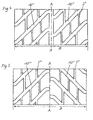
- the tread profiles shown in the drawing figures 2 to 7 are each considered over their width B, which corresponds to the width in the footprint according to the ETRTO Standards Manual.
- a wide circumferential groove 2 is arranged along the tire circumferential center line A-A, which, as shown, can be designed as a straight circumferential groove.
- Wide, diagonally running grooves 10 are arranged as main grooves in each tread half, which in this exemplary embodiment, except for the area of their openings into the circumferential groove 2 or their transition areas on the tread edges, where the grooves 10 each have end sections bent in the transverse direction of the tread profile, run at least essentially in a straight line.
- the grooves 10 running in one tread half are mutually inclined by the arrowed arrangement to the grooves 10 running in the other tread half and form an angle ⁇ with the circumferential center line AA, which is between 35 +/- 20 °, in particular between 35 +/- 10 ° is selected.
- the grooves 10 in one tread half are offset from the grooves 10 in the second tread half. This offset can be carried out up to half the mutual distance between adjacent grooves 10.
- Such a tire is arranged on the vehicle in such a way that the end regions of the grooves 10 on the inside of the tread first enter the contact surface with the ground.
- the grooves 10 are connected to each other in each tread half by relatively narrow, at least substantially circumferential longitudinal grooves 3, whereby a block structure is formed.
- the average width of the narrow longitudinal grooves 3 is chosen between 10 and 60%, in particular 20 to 40%, of the width of the grooves 10.
- the course of the longitudinal grooves 3 can deviate from the circumferential direction by +/- 10 °, in particular +/- 5 °.
- the wide grooves 10 are acoustically coupled by the narrow longitudinal grooves 3. It is therefore advantageous to offset the longitudinal grooves 3 in the transverse direction of the tire so that there is no aligned arrangement of the longitudinal grooves 3.
- the offset of the longitudinal grooves 3 results in a block structure in which the number of blocks 4 between adjacent grooves 10 differs from one another, so that in the illustrated embodiment, three blocks 4 and four blocks 4 are alternately present in each tread half between adjacent grooves 10.
- This profile design has 3 good abrasion and aquaplaning properties due to the longitudinal grooves. At the same time, it is ensured that sound radiation directed in and against the direction of travel and a reduction in the lateral sound radiation is achieved.
- the described offset of the longitudinal grooves 3 additionally causes the energy of the blocks striking the ground to be distributed over time during the rolling of the tire, which has an overall favorable effect on the sound pressure level.
- the illustrated offset of the grooves 10 running in one tread half compared to those running in the other tread half 10 is dispensed with, so that the grooves 10 open into the circumferential groove 2 without mutual offset.
- the tread pattern is designed such that, viewed in the transverse direction of the profile, the number of grooves 10, depending on the tire dimension, is between 6 and 12, in particular between 8 and 10.
- the width of the grooves 10 is kept at least substantially constant, all grooves 10 in particular having the same width.
- the cross section of the grooves 10 can be U-shaped, V-shaped or the like, symmetrical or asymmetrical.
- known stone rejection measures can be taken, such as raising the base of the groove.
- the circumferential groove 2 which runs in the circumferential direction, can also be designed in a wave-like or zig-zag shape, in deviation from the illustrated embodiment will.
- the proportion of wide grooves 10, longitudinal grooves 3 and other measures that reduce the negative proportion, such as bevels of blocks and the like, is chosen so that a total of a negative proportion of 20 to 40%, based on the total area in the ground contact area.
- Fig. 3 shows a variant of the embodiment shown in Fig. 2, in which, in addition to a central circumferential groove 2 ', grooves 10' are arranged in each tread half, each of which has a corresponding slope over a large part of its lengths. Accordingly, this profile variant is not directional.
- the mouth areas of the grooves 10 ' both in the area of the circumferential groove 2' and at the tread edges, are again designed such that the grooves 10 'each open into the circumferential groove 2' via a rounded kink in the middle or at the tread edge the shoulder areas run out.
- the further configuration of the profile with longitudinal grooves 3 ' corresponds to that according to FIG. 2, as does the angulation of the grooves 10' and their other configuration.
- the exemplary embodiment shown in FIG. 4 differs from that according to FIG. 3 only in that the grooves 10 ′′ in one tread half are offset in the circumferential direction compared to the grooves 10 ′′ in the other tread half.
- the longitudinal grooves 3 '' are provided analogously.
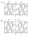
- FIG. 5 corresponds to that in FIG. 2 except for the design of the central region.
- there are grooves 10 III longitudinal grooves 3 III in each tread half, each with the appropriate angulation and offset, arranged.
- No circumferential groove is now provided in the tread center area, so that the grooves 10 III end there as pocket grooves, preferably and as shown, forming a rounded kink at the respective ends.
- the central tread area is therefore more closed than in the embodiment variants according to FIGS. 2 to 4, which results in a certain reduction in the effectiveness of the physical principle of action on which these embodiments are based.
- the closed grooves 10 III emit something more noise, mutual extinction is mainly possible in the inlet and outlet.
- FIG. 6 shows a variant essentially corresponding to FIG. 4, which accordingly has grooves 10 IV that are the same in both tread halves, the central region of the tread profile is designed analogously to the variant according to FIG. 4, with no offset of the grooves 10 running in one tread half IV compared to those of the grooves 10 IV running in the second tread half.
- FIG. 7 A variant with an offset of the grooves 10 V in one tread half compared to the grooves 10 V in the second tread half is shown in FIG. 7.
- the other configuration of the variants shown in FIGS. 6 and 7 basically corresponds to that according to FIG. 5.
- lamellae fine incisions, narrow, additional incisions and the like can be provided.
- a pitch length variation which is well known from the prior art, can be carried out for all of the design variants.
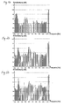
- 1a, 1b, 2a, 2b and 5a, 5b illustrate the effectiveness of the present invention on the basis of images of measured sound fields and determined frequency spectra.
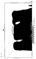
- 1a, 2a and 5a show in gray-coded, three-dimensional representations the sound intensity or sound power emitted by the tire in the lateral direction, through a plane parallel to the tire running direction, perpendicular to the ground and at a distance of approximately 20 cm from the tire sidewall.
- the measurements were carried out on a drum test bench at a speed of 70 km / h.
- the dimensions of the tire, the rim and the drum on which the tire runs are outlined in the illustrations.
- the Line marks on the rectangle surrounding the representations show the measuring grid. At each crossing point of the vertical and horizontal line connecting these markings, the sound intensity was determined perpendicular to the plane of the drawing and displayed as a gray value.
- the scale at the foot of the diagrams shows the sound power assigned to each gray level in dB.
- FIG. 1a now shows the extent and type of the sound field measured from the side of a truck tire with a traction profile designed according to the prior art.
- the tire measured had the tread configuration shown in FIG. 1 with a pronounced block structure.
- the sound field of this known tire is clearly spread out with the intensity distribution characterized by the different gray levels.
- the frequency spectrum shown in Fig. 1b shows pronounced peaks in certain frequency ranges and a high sound pressure level.
- FIG. 2a The sound field measured with a tire whose profile was equipped according to FIG. 2 is shown in FIG. 2a.
- the noise emission in the lateral direction is significantly reduced.
- the frequency spectrum (Fig. 2b) shows less pronounced peaks and a significantly reduced sound power.
- the frequency spectrum (FIG. 5b) also shows a reduced sound power and an equalization with regard to the frequency peaks.
- the profile is divided by the circumferential center line into two tread areas, which are thus the two tread halves.
- the profile can also be divided into tread areas that are not the two tread halves, for example by arranging the circumferential groove offset with respect to the circumferential center line. This results in asymmetrical profile configurations, which are also within the scope of the present invention.
Landscapes
- Engineering & Computer Science (AREA)
- Mechanical Engineering (AREA)
- Tires In General (AREA)
- Valve-Gear Or Valve Arrangements (AREA)
- Mechanical Operated Clutches (AREA)
- Yarns And Mechanical Finishing Of Yarns Or Ropes (AREA)
Applications Claiming Priority (2)
| Application Number | Priority Date | Filing Date | Title |
|---|---|---|---|
| DE19548731A DE19548731C2 (de) | 1995-12-23 | 1995-12-23 | Radialreifen |
| DE19548731 | 1995-12-23 |
Publications (2)
| Publication Number | Publication Date |
|---|---|
| EP0780246A1 true EP0780246A1 (fr) | 1997-06-25 |
| EP0780246B1 EP0780246B1 (fr) | 2001-05-23 |
Family
ID=7781419
Family Applications (1)
| Application Number | Title | Priority Date | Filing Date |
|---|---|---|---|
| EP96120690A Expired - Lifetime EP0780246B1 (fr) | 1995-12-23 | 1996-12-20 | Bandage pneumatique radial |
Country Status (3)
| Country | Link |
|---|---|
| EP (1) | EP0780246B1 (fr) |
| AT (1) | ATE201355T1 (fr) |
| DE (2) | DE19548731C2 (fr) |
Cited By (1)
| Publication number | Priority date | Publication date | Assignee | Title |
|---|---|---|---|---|
| CN100567034C (zh) * | 2004-11-25 | 2009-12-09 | 东洋橡胶工业株式会社 | 充气轮胎 |
Citations (7)
| Publication number | Priority date | Publication date | Assignee | Title |
|---|---|---|---|---|
| GB736068A (en) * | 1952-11-13 | 1955-08-31 | Trelleborgs Gummifabriks Ab | Improvements in or relating to non-skid treads for the tyres of motor vehicles |
| GB738143A (en) * | 1953-06-15 | 1955-10-05 | Sigurd Ingemann Olsen | Improvements in the treads of tyres for motor vehicles |
| GB2014091A (en) * | 1978-02-14 | 1979-08-22 | Goodyear Tire & Rubber | Pneumatic tire tread |
| JPS61115704A (ja) * | 1984-11-09 | 1986-06-03 | Sumitomo Rubber Ind Ltd | 自動二輪車用タイヤ |
| EP0434967A2 (fr) * | 1989-12-29 | 1991-07-03 | Continental Aktiengesellschaft | Profil de bande de roulement pour pneumatiques |
| EP0613794A1 (fr) * | 1993-03-02 | 1994-09-07 | PIRELLI REIFENWERKE GmbH | Bande de roulement pour bandage pneumatique d'hiver |
| EP0625435A1 (fr) * | 1993-05-20 | 1994-11-23 | Bridgestone Corporation | Bandages pneumatiques |
Family Cites Families (5)
| Publication number | Priority date | Publication date | Assignee | Title |
|---|---|---|---|---|
| JPS62175204A (ja) * | 1986-01-29 | 1987-07-31 | Yokohama Rubber Co Ltd:The | 乗用車用空気入りラジアルタイヤ |
| JPH03143706A (ja) * | 1989-10-30 | 1991-06-19 | Yokohama Rubber Co Ltd:The | 空気入りタイヤの装着方法 |
| DE4039261A1 (de) * | 1989-12-29 | 1991-07-04 | Continental Ag | Laufflaechenprofil fuer fahrzeugreifen |
| US5318085A (en) * | 1990-10-22 | 1994-06-07 | General Tire | Radial tire having reduced treadwear |
| US5435364A (en) * | 1990-12-28 | 1995-07-25 | Sumitomo Rubber Industries, Ltd. | Pneumatic radial tire with four main grooves |
-
1995
- 1995-12-23 DE DE19548731A patent/DE19548731C2/de not_active Expired - Fee Related
-
1996
- 1996-12-20 AT AT96120690T patent/ATE201355T1/de not_active IP Right Cessation
- 1996-12-20 EP EP96120690A patent/EP0780246B1/fr not_active Expired - Lifetime
- 1996-12-20 DE DE59606952T patent/DE59606952D1/de not_active Expired - Lifetime
Patent Citations (7)
| Publication number | Priority date | Publication date | Assignee | Title |
|---|---|---|---|---|
| GB736068A (en) * | 1952-11-13 | 1955-08-31 | Trelleborgs Gummifabriks Ab | Improvements in or relating to non-skid treads for the tyres of motor vehicles |
| GB738143A (en) * | 1953-06-15 | 1955-10-05 | Sigurd Ingemann Olsen | Improvements in the treads of tyres for motor vehicles |
| GB2014091A (en) * | 1978-02-14 | 1979-08-22 | Goodyear Tire & Rubber | Pneumatic tire tread |
| JPS61115704A (ja) * | 1984-11-09 | 1986-06-03 | Sumitomo Rubber Ind Ltd | 自動二輪車用タイヤ |
| EP0434967A2 (fr) * | 1989-12-29 | 1991-07-03 | Continental Aktiengesellschaft | Profil de bande de roulement pour pneumatiques |
| EP0613794A1 (fr) * | 1993-03-02 | 1994-09-07 | PIRELLI REIFENWERKE GmbH | Bande de roulement pour bandage pneumatique d'hiver |
| EP0625435A1 (fr) * | 1993-05-20 | 1994-11-23 | Bridgestone Corporation | Bandages pneumatiques |
Non-Patent Citations (1)
| Title |
|---|
| PATENT ABSTRACTS OF JAPAN vol. 010, no. 301 (M - 525) 14 October 1986 (1986-10-14) * |
Cited By (1)
| Publication number | Priority date | Publication date | Assignee | Title |
|---|---|---|---|---|
| CN100567034C (zh) * | 2004-11-25 | 2009-12-09 | 东洋橡胶工业株式会社 | 充气轮胎 |
Also Published As
| Publication number | Publication date |
|---|---|
| EP0780246B1 (fr) | 2001-05-23 |
| DE59606952D1 (de) | 2001-06-28 |
| ATE201355T1 (de) | 2001-06-15 |
| DE19548731A1 (de) | 1997-06-26 |
| DE19548731C2 (de) | 2001-09-27 |
Similar Documents
| Publication | Publication Date | Title |
|---|---|---|
| DE69503938T2 (de) | Luftreifen | |
| AT402178B (de) | Laufstreifen für einen fahrzeugluftreifen | |
| DE60207836T2 (de) | Laufflächenprofil für einen fahrzeugreifen | |
| AT402179B (de) | Laufstreifen für einen fahrzeugluftreifen | |
| DE102007016113A1 (de) | Luftreifen | |
| EP0675011A1 (fr) | Bandage pneumatique avec blocs éjecteurs de pierres | |
| DE4306483A1 (de) | Laufflächenprofil für Winterreifen | |
| DE19702675C2 (de) | Profil für PKW-Luftreifen | |
| DE19548733C2 (de) | Radialreifen | |
| EP0715972B1 (fr) | Bandage pneumatique pour véhicule | |
| EP1533140B1 (fr) | Profil de la bande de roulement d'un pneumatique pour véhicules | |
| EP0479761B1 (fr) | Bandage pneumatique pour véhicules | |
| DE19548731C2 (de) | Radialreifen | |
| EP3551475B1 (fr) | Pneumatique de véhicule | |
| AT394002B (de) | Radialreifen fuer raeder von lkw-antriebsachsen | |
| EP0718123B1 (fr) | Bandage pneumatique pour véhicule | |
| EP0782935A2 (fr) | Ensemble formé d'un véhicule et de pneumatiques, et équipé d'au moins un dispositif absorbant le bruit | |
| EP0780247B1 (fr) | Bandage pneumatique radial | |
| DE19548734C2 (de) | Radialreifen | |
| EP2142388B1 (fr) | Pneumatique de véhicule | |
| EP4347276A1 (fr) | Pneu pour véhicule | |
| DE19722572A1 (de) | Asymetrisch und drehsinngebunden profilierte Lauffläche für Fahrzeugluftreifen | |
| EP0755809B1 (fr) | Bandage pour véhicules | |
| AT403358B (de) | Fahrzeugreifen mit einem laufstreifenprofil | |
| DE4032166A1 (de) | Radialreifen, insbesondere fuer allrad-fahrzeuge |
Legal Events
| Date | Code | Title | Description |
|---|---|---|---|
| PUAI | Public reference made under article 153(3) epc to a published international application that has entered the european phase |
Free format text: ORIGINAL CODE: 0009012 |
|
| AK | Designated contracting states |
Kind code of ref document: A1 Designated state(s): AT DE FR GB IT |
|
| 17P | Request for examination filed |
Effective date: 19971229 |
|
| 17Q | First examination report despatched |
Effective date: 19991109 |
|
| GRAG | Despatch of communication of intention to grant |
Free format text: ORIGINAL CODE: EPIDOS AGRA |
|
| GRAG | Despatch of communication of intention to grant |
Free format text: ORIGINAL CODE: EPIDOS AGRA |
|
| GRAH | Despatch of communication of intention to grant a patent |
Free format text: ORIGINAL CODE: EPIDOS IGRA |
|
| GRAH | Despatch of communication of intention to grant a patent |
Free format text: ORIGINAL CODE: EPIDOS IGRA |
|
| GRAA | (expected) grant |
Free format text: ORIGINAL CODE: 0009210 |
|
| AK | Designated contracting states |
Kind code of ref document: B1 Designated state(s): AT DE FR GB IT |
|
| REF | Corresponds to: |
Ref document number: 201355 Country of ref document: AT Date of ref document: 20010615 Kind code of ref document: T |
|
| REF | Corresponds to: |
Ref document number: 59606952 Country of ref document: DE Date of ref document: 20010628 |
|
| ITF | It: translation for a ep patent filed | ||
| GBT | Gb: translation of ep patent filed (gb section 77(6)(a)/1977) |
Effective date: 20010816 |
|
| ET | Fr: translation filed | ||
| REG | Reference to a national code |
Ref country code: GB Ref legal event code: IF02 |
|
| PLBE | No opposition filed within time limit |
Free format text: ORIGINAL CODE: 0009261 |
|
| STAA | Information on the status of an ep patent application or granted ep patent |
Free format text: STATUS: NO OPPOSITION FILED WITHIN TIME LIMIT |
|
| 26N | No opposition filed | ||
| PGFP | Annual fee paid to national office [announced via postgrant information from national office to epo] |
Ref country code: GB Payment date: 20041213 Year of fee payment: 9 |
|
| PG25 | Lapsed in a contracting state [announced via postgrant information from national office to epo] |
Ref country code: IT Free format text: LAPSE BECAUSE OF NON-PAYMENT OF DUE FEES;WARNING: LAPSES OF ITALIAN PATENTS WITH EFFECTIVE DATE BEFORE 2007 MAY HAVE OCCURRED AT ANY TIME BEFORE 2007. THE CORRECT EFFECTIVE DATE MAY BE DIFFERENT FROM THE ONE RECORDED. Effective date: 20051220 Ref country code: GB Free format text: LAPSE BECAUSE OF NON-PAYMENT OF DUE FEES Effective date: 20051220 |
|
| GBPC | Gb: european patent ceased through non-payment of renewal fee |
Effective date: 20051220 |
|
| PGFP | Annual fee paid to national office [announced via postgrant information from national office to epo] |
Ref country code: AT Payment date: 20061213 Year of fee payment: 11 |
|
| PG25 | Lapsed in a contracting state [announced via postgrant information from national office to epo] |
Ref country code: AT Free format text: LAPSE BECAUSE OF NON-PAYMENT OF DUE FEES Effective date: 20071220 |
|
| PGFP | Annual fee paid to national office [announced via postgrant information from national office to epo] |
Ref country code: DE Payment date: 20101202 Year of fee payment: 15 |
|
| PGFP | Annual fee paid to national office [announced via postgrant information from national office to epo] |
Ref country code: FR Payment date: 20120102 Year of fee payment: 16 |
|
| REG | Reference to a national code |
Ref country code: DE Ref legal event code: R119 Ref document number: 59606952 Country of ref document: DE Effective date: 20120703 |
|
| PG25 | Lapsed in a contracting state [announced via postgrant information from national office to epo] |
Ref country code: DE Free format text: LAPSE BECAUSE OF NON-PAYMENT OF DUE FEES Effective date: 20120703 |
|
| REG | Reference to a national code |
Ref country code: FR Ref legal event code: ST Effective date: 20130830 |
|
| PG25 | Lapsed in a contracting state [announced via postgrant information from national office to epo] |
Ref country code: FR Free format text: LAPSE BECAUSE OF NON-PAYMENT OF DUE FEES Effective date: 20130102 |