EP0780631A2 - Procédé et brûleur pour la combustion d'hydrogène - Google Patents
Procédé et brûleur pour la combustion d'hydrogène Download PDFInfo
- Publication number
- EP0780631A2 EP0780631A2 EP96119733A EP96119733A EP0780631A2 EP 0780631 A2 EP0780631 A2 EP 0780631A2 EP 96119733 A EP96119733 A EP 96119733A EP 96119733 A EP96119733 A EP 96119733A EP 0780631 A2 EP0780631 A2 EP 0780631A2
- Authority
- EP
- European Patent Office
- Prior art keywords
- burner
- hydrogen
- air
- burner according
- combustion
- Prior art date
- Legal status (The legal status is an assumption and is not a legal conclusion. Google has not performed a legal analysis and makes no representation as to the accuracy of the status listed.)
- Granted
Links
Images


Classifications
-
- F—MECHANICAL ENGINEERING; LIGHTING; HEATING; WEAPONS; BLASTING
- F23—COMBUSTION APPARATUS; COMBUSTION PROCESSES
- F23D—BURNERS
- F23D14/00—Burners for combustion of a gas, e.g. of a gas stored under pressure as a liquid
- F23D14/46—Details
- F23D14/70—Baffles or like flow-disturbing devices
-
- F—MECHANICAL ENGINEERING; LIGHTING; HEATING; WEAPONS; BLASTING
- F23—COMBUSTION APPARATUS; COMBUSTION PROCESSES
- F23D—BURNERS
- F23D14/00—Burners for combustion of a gas, e.g. of a gas stored under pressure as a liquid
- F23D14/20—Non-premix gas burners, i.e. in which gaseous fuel is mixed with combustion air on arrival at the combustion zone
-
- F—MECHANICAL ENGINEERING; LIGHTING; HEATING; WEAPONS; BLASTING
- F23—COMBUSTION APPARATUS; COMBUSTION PROCESSES
- F23C—METHODS OR APPARATUS FOR COMBUSTION USING FLUID FUEL OR SOLID FUEL SUSPENDED IN A CARRIER GAS OR AIR
- F23C2900/00—Special features of, or arrangements for combustion apparatus using fluid fuels or solid fuels suspended in air; Combustion processes therefor
- F23C2900/9901—Combustion process using hydrogen, hydrogen peroxide water or brown gas as fuel
-
- F—MECHANICAL ENGINEERING; LIGHTING; HEATING; WEAPONS; BLASTING
- F23—COMBUSTION APPARATUS; COMBUSTION PROCESSES
- F23D—BURNERS
- F23D2209/00—Safety arrangements
- F23D2209/20—Flame lift-off / stability
Definitions
- the invention relates to a method for burning hydrogen and a burner for carrying out the method.
- NOx nitrogen oxide
- a distribution chamber of plate-like shape for the hydrogen is inserted transversely to the flow direction of the air, hereinafter referred to as the main flow direction, into a combustion chamber, the distribution chamber being penetrated in the main flow direction by a multiplicity of air guide tubes with an inlet opening and an outlet opening.
- Each air duct is connected to the distribution chamber via small bores, which are arranged near the inlet opening.
- the invention has for its object to provide a method for diffusion combustion of H2 and a burner for performing this method so that a drastic increase in the combustion zones, a significant reduction in NOx formation compared to previous burners with diffusion combustion is achieved.
- An advantage of the embodiment according to claim 2 is that the hydrogen exerts a particularly good cooling effect on the structure.
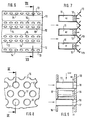
- Fin. 1 to 4 show a burner for burning H2 for installation, for example, in the combustion chamber of a gas turbine.
- the burner has a plate-like shape and is installed transversely to the main flow direction in the combustion chamber.
- the edge area of the burner and its connection to the combustion chamber housing, not shown, is not shown and can be of any design.
- the burner consists of a first perforated plate 2 and a second perforated plate 3, which are kept at a constant distance d by a plurality of guide tubes 4.
- the holes can be arranged according to certain matrix patterns.
- the first perforated plate 2 consists for example of a suitable metal and is impermeable to gas.
- the second perforated plate 3 is gas-permeable and consists of a suitable porous material, for example of a sintered metal.
- the holes in the two plates 2, 3 are congruent so that each hole in the first plate 2 forms a pair of holes with the associated hole in the second plate 3.
- the burner is held together essentially by inserting and fixing a guide tube 4 as a spacer in each pair of holes.
- the guide tubes 4 have peripheral beads 5 which are rolled outwards.
- the guide tubes 4 are fixed in the perforated plate 2, for example, by soldering or welding, whereas the fixing in the plate 3 can be carried out, for example, by rolling or flanging.
- each guide tube 4 an air guide pin 6 is used, as shown in FIGS. 3 and 4 is shown enlarged.
- the guide pin basically consists of a cylindrical rotating body with a stop 6a, a guide part 6b, a holder 8 and a disk 9.
- the outer diameter of the guide part 6b corresponds approximately to the inner diameter of the guide tube 4 and has four axial guide channels 7 in the example embodiment shown .
- the holder 8 is attached to the guide part on the right in FIG.
- the stop 6a is formed by a region which is short in the axial direction and whose outer diameter is larger than that of the guide part 6b.
- a guide pin 6 is inserted into each guide tube 4 from the air side of the burner until the stop 6a abuts the perforated plate 2 and is permanently fixed in this position.
- Such an assembly forms an injector.
- gaseous hydrogen is introduced into the distribution chamber between the perforated plates 2, 3. Air is also blown into the combustion chamber through the guide tubes.
- the hydrogen flows within the distribution chamber transversely to the main flow direction and is distributed in a fine distribution to the local areas of the porous perforated plate 3, through which it enters the combustion chamber and forms a hydrogen environment here.
- an air flow in the manner of a cone jacket arises as a result of the deflection through the disk 9, which enters a process of forming a mixture with the surrounding hydrogen and thereby forms a rotationally symmetrical diffusion flame.
- the interaction of each other is more conducive to the activation of the mixing process adjacent cone flames.
- the geometry of the guide bolts 6 is selected so that when they are inserted up to the respective stop 6a, a predetermined deflection, ie a predetermined flame shape, results.
- the stops 6a are omitted for reasons of weight.
- the guide pins 6 are inserted into the guide tubes 4 in a predetermined axial position by means of a manufacturing device. Due to the extremely simple construction of the injectors, they can be miniaturized in such a way that a much larger number of them can be installed per combustion chamber. As a result of the miniaturization in the order of magnitude specified, the burning zones designed according to the invention are called micro-burning zones.
- the figures 6 and 7 show a further embodiment of a burner according to the invention, consisting of individual elongated distributor channels 11 of U-shaped cross section which are provided for the hydrogen and which are closed off from the combustion chamber by walls 12 made of a porous sintered metal.
- the channels 11 are connected to one another by perforated profiles 13 of angular cross section in such a way that the free longitudinal edges of a perforated profile 13 are fastened to the longitudinal edges of two adjacent distributor channels 11.
- the holes 14 are made in the strip-shaped legs of the perforated profiles 13 at a uniform distance.
- gaseous hydrogen is introduced into the distribution channels 11.
- air is blown into the combustion chamber through the bores 14.
- the hydrogen flows within the distribution channels 11 transversely to the main flow direction and is distributed through a fine distribution to the local areas of the porous walls 12, through which it enters the combustion chamber and forms a hydrogen environment here.
- a stoichiometric zone forms in the region of each bore 14, which zone is ignited when the Brenners forms its own flame.
- This burner is particularly simple and can be manufactured as a sheet metal construction. One can proceed, for example, in such a way that the U-shaped distribution channels 11 are bent from sheet metal, each U-leg being connected in one piece with an obliquely angled perforated strip. After the porous walls 12 have been inserted, adjacent channels 11 are connected to one another, for example by welding along the free edges of the perforated strips.
- This burner can be miniaturized in such a way that several thousand combustion zones can be reached within one combustion chamber.
- the H2 is distributed over the distribution chamber or via the distribution channels to thousands of micro-combustion zones, so that, as it were, microdiffusion combustion of the hydrogen takes place.
- the main advantage of this inverse hydrogen diffusion combustion is that the structure is cooled well by the H2.
- porous metallic materials can also be used instead of the porous sintered metals.
- Porous materials based on metallic fibers such as are known, for example, under the name "felt metal" are also suitable.
- the porous material consists of a ceramic material.
- a perforated plate with a defined fine hole pattern can be placed upstream of a relatively thin layer of porous material or used alone.
- the figures 8 to 11 show a further embodiment of a burner which, in contrast to the previous ones, does not work with inverse but with regular diffusion combustion.
- This burner again consists essentially of two congruent perforated plates, which are designated 15 and 16 here.
- the two perforated plates are firmly connected to one another via guide tubes 17, each having an inlet opening and an outlet opening, so that a distribution chamber is formed again.
- a plurality of bores 18 are made in the same angular division on the guide tubes 17.
- a guide pin 19 consisting of a stop 20, a guide part 21 and a free jet part 22 is inserted into each guide tube 17, the free jet part practically representing an axial section with a reduced diameter.
- the stop 20 and the guide part 21 have a number of axially extending grooves 23, the depth of which can extend to the outer diameter of the free jet part 22.
- the number of bores 18 corresponds to that of the grooves 23.
- FIG. 12 shows various settings of the burner described above.
- the guide pin with the grooves 23 is set opposite the guide tube 17 with the holes 18 so that the hydrogen is injected through the holes 18 into the gaps between the air jets that arrive through the grooves 23.
- Fig. 13 shows the guide pin in a position in which the guide part 21 reaches close to the holes 18.
- the hydrogen jet can only be deflected downstream.
- the guide part 21 is fixed in the guide tube 17 in such a way that there is a somewhat greater distance from the bores 18, as shown in FIG. 14, a certain recirculation can occur.
- 15 finally shows a configuration in which the air jets arriving through the grooves 23 precisely meet the hydrogen jets entering through the bores.
- FIGS. 16 and 17 show an embodiment in which the hydrogen jets and the air jets are guided separately until they enter the combustion chamber.
- the guide tubes 17 with the bores 18 described above are used. These are again inserted into the perforated plates 15 and 16, of which only the one labeled 16 can be seen here.
- the guide pin 24 used here again has the grooves 23, but is otherwise provided with two significant changes.
- the bolt with a constant diameter is guided almost to the outlet cross section.
- small axially extending guide channels 25 are attached centrally to the material areas located between the grooves 23.
- the respective guide pin 24 is inserted into the guide tube 17 in question so that each bore 18 opens into a guide channel 25.
- the beginning of the diffusion between hydrogen and air is placed in an area downstream of the perforated plate 16, for example in order to avoid excessive thermal structural loads. With these solutions, the flames stabilize at the mouths of the guide channels 25.
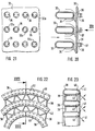
- FIGS. 18 and 19 show an embodiment of a burner for regular diffusion combustion of the two-dimensional type.
- This burner again consists of individual elongated distribution channels 26 provided for the H2, which, however, in contrast to the distribution channels 11 according to FIGS. 6 and 7 have a closed cross section.
- This cross section is essentially determined by a flat rectangular shape, which, however, has a roof edge 26a in the area on the right in the picture.
- Fine bores 27 are arranged in a staggered arrangement on both sides of the roof edge.
- the individual channels 26 are held at a mutual distance by a bracket, not shown, so that they form a grid which, according to FIG. 19, the air can flow through from left to right.
- the burner further comprises strip-shaped gap plates 28, in the longitudinal edges of which gaps 29 are incorporated.
- the gap plates 28 are each fixed between two distributor channels 26 in the area of the bores 27 by a bracket (not shown) such that a gap 29 is assigned to each bore 27.
- a bracket (not shown) such that a gap 29 is assigned to each bore 27.
- several finer bores can be arranged.
- the figures 20 and 21 show a burner with a one-piece perforated plate 32 with holes 32a, to which a plurality of distributor channels 33 are fastened by means of brackets 34.
- the distribution channels 33 have a long round cross section and have a large number of bores 35 in their area facing the perforated plate 32.
- the brackets 34 can be formed from wire or sheet metal. As shown in FIG. 21, two holes 35 are assigned to each hole 32a of the perforated plate 32, whereby H2 can emerge according to the arrows 37.
- the figures 22 and 23 show a further embodiment of a burner.
- the partial view according to FIG. 22 shows curved distribution channels 38, which are part of an annular burner and, according to FIG. 23, have a long round cross section.
- Each distribution channel forms a closed ring, which is connected to the hydrogen line via its own connection.
- the burner is held together, for example, by wave-shaped separators 39 arranged between the individual distribution channels 38, which are connected to the distribution channels 38, for example by welding.
- the separators 39 are each formed from a sheet metal strip and ensure a sufficient distance between the individual distributor channels 38 for the passage of air.
- a distributor channel 38 is combined with a separator 39 by winding to form a disc-shaped or ring-shaped burner, so that the distributor channel 38 is given a spiral shape.
- bores are again provided on the distribution channel 38, which are designated here by 40.
- two hydrogen beams 41 intersect at one point.
- a common feature of the annular and the spiral distribution channels is that they have a curved shape. In principle, these burners work in the same way as those already used in conjunction with FIGS. 18 to 21 described.
Landscapes
- Engineering & Computer Science (AREA)
- Chemical & Material Sciences (AREA)
- Combustion & Propulsion (AREA)
- Mechanical Engineering (AREA)
- General Engineering & Computer Science (AREA)
- Gas Burners (AREA)
- Pre-Mixing And Non-Premixing Gas Burner (AREA)
Applications Claiming Priority (2)
| Application Number | Priority Date | Filing Date | Title |
|---|---|---|---|
| DE19547506A DE19547506B4 (de) | 1995-12-19 | 1995-12-19 | Verfahren und Brenner zum Verbrennen von Wasserstoff |
| DE19547506 | 1995-12-19 |
Publications (3)
| Publication Number | Publication Date |
|---|---|
| EP0780631A2 true EP0780631A2 (fr) | 1997-06-25 |
| EP0780631A3 EP0780631A3 (fr) | 1998-09-30 |
| EP0780631B1 EP0780631B1 (fr) | 2003-10-29 |
Family
ID=7780607
Family Applications (1)
| Application Number | Title | Priority Date | Filing Date |
|---|---|---|---|
| EP96119733A Expired - Lifetime EP0780631B1 (fr) | 1995-12-19 | 1996-12-10 | Procédé et brûleur pour la combustion d'hydrogène |
Country Status (4)
| Country | Link |
|---|---|
| EP (1) | EP0780631B1 (fr) |
| JP (1) | JP3830596B2 (fr) |
| DE (2) | DE19547506B4 (fr) |
| RU (1) | RU2152559C2 (fr) |
Cited By (8)
| Publication number | Priority date | Publication date | Assignee | Title |
|---|---|---|---|---|
| WO2004103417A1 (fr) * | 2003-05-22 | 2004-12-02 | Ntu Ventures Private Limited | Procede et appareil permettant de steriliser des instruments et des dispositifs utilises dans le domaine medical ou en laboratoire |
| EP2930430A1 (fr) * | 2014-04-07 | 2015-10-14 | Siemens Aktiengesellschaft | Bec de brûleur et brûleur d'une turbine à gaz |
| FR3095497A1 (fr) | 2019-04-24 | 2020-10-30 | Henri Becu | Bruleur en nano materiaux frittes pour la combustion par flamme d’un premelange gazeux du type comburant/combustible |
| CN115355530A (zh) * | 2022-08-12 | 2022-11-18 | 中国航发沈阳发动机研究所 | 一种半圆柱型射流孔的氢燃料燃烧室头部结构 |
| WO2023179825A1 (fr) * | 2022-03-23 | 2023-09-28 | Dürr Systems Ag | Dispositif de type brûleur |
| CN117823946A (zh) * | 2023-12-29 | 2024-04-05 | 西安交通大学 | 富氢或纯氢灵活燃料燃烧稳焰喷头与燃烧器 |
| EP4411236A1 (fr) * | 2023-02-02 | 2024-08-07 | Pratt & Whitney Canada Corp. | Système de carburant avec injecteurs disposés radialement pour moteur à turbine à gaz à hydrogène |
| CN121275968A (zh) * | 2025-12-11 | 2026-01-06 | 华东理工大学 | 一种基于逆扩散火焰燃烧器的材料高温氢渗透模拟实验装置及方法 |
Families Citing this family (15)
| Publication number | Priority date | Publication date | Assignee | Title |
|---|---|---|---|---|
| RU2410599C2 (ru) * | 2005-01-12 | 2011-01-27 | Дзе Бэбкок энд Уилкокс Компани | Матричное средство для уменьшения объема горения |
| DE102006046053B4 (de) * | 2006-09-28 | 2008-11-20 | Green Vision Holding B.V. | Nicht vorgemischter Brenner |
| US8261555B2 (en) * | 2010-07-08 | 2012-09-11 | General Electric Company | Injection nozzle for a turbomachine |
| UA102400C2 (uk) * | 2011-01-24 | 2013-07-10 | Товариство З Обмеженою Відповідальністю "Науково-Проектний Інститут Хімічних Технологій "Хімтехнологія" | Пальник реактора одержання ацетилену |
| US8893501B2 (en) * | 2011-03-28 | 2014-11-25 | General Eletric Company | Combustor crossfire tube |
| CN106461211B (zh) * | 2014-05-30 | 2019-03-22 | 川崎重工业株式会社 | 燃气涡轮发动机的燃烧装置 |
| JP6285022B2 (ja) * | 2014-05-30 | 2018-02-28 | 川崎重工業株式会社 | ガスタービンエンジンの燃焼装置 |
| JP6535525B2 (ja) * | 2015-07-01 | 2019-06-26 | 三菱日立パワーシステムズ株式会社 | ガスタービン燃焼器 |
| EP3805107B1 (fr) | 2019-10-08 | 2025-01-22 | Airbus SAS | Système de propulsion hybride pour aéronefs, procédé de fonctionnement d'un système de propulsion hybride et aéronef hybride |
| JP7222872B2 (ja) * | 2019-11-08 | 2023-02-15 | 株式会社デンソー | ガスタービンの燃焼器 |
| WO2022202103A1 (fr) * | 2021-03-25 | 2022-09-29 | 株式会社Ihi | Dispositif de combustion et système de turbine à gaz |
| RU2767237C1 (ru) * | 2021-05-11 | 2022-03-17 | Федеральное государственное бюджетное учреждение науки Институт теоретической и прикладной механики им. С.А. Христиановича Сибирского отделения Российской академии наук (ИТПМ СО РАН) | Способ организации диффузионного горения микроструи газообразного топлива |
| EP4173956B1 (fr) | 2021-10-29 | 2026-03-18 | Airbus S.A.S. | Système de propulsion hybride pour propulser un aéronef, son procédé de fonctionnement et aéronef hybride |
| KR20230091605A (ko) | 2021-12-16 | 2023-06-23 | 한화에어로스페이스 주식회사 | 직교 배열되는 채널을 포함하는 연소 장치 |
| KR20240100001A (ko) * | 2022-12-22 | 2024-07-01 | 주식회사 경동나비엔 | 버너 및 이를 포함하는 물 가열기 |
Family Cites Families (16)
| Publication number | Priority date | Publication date | Assignee | Title |
|---|---|---|---|---|
| DE372932C (de) * | 1923-04-05 | Karol Hand | Gasheizbrennerkopf | |
| US1968395A (en) * | 1932-02-03 | 1934-07-31 | Carl L Zeller | Gas burner |
| AT299490B (de) * | 1968-10-10 | 1972-06-26 | British Petroleum Co | Brenner für flüssige und/oder gasförmige Brennstoffe |
| GB1263611A (en) * | 1969-05-19 | 1972-02-16 | British Petroleum Co | Gas burner |
| GB1343398A (en) * | 1969-12-24 | 1974-01-10 | Delaney Gallay Ltd | Gas burners |
| DE2034352C2 (de) * | 1970-07-10 | 1984-02-23 | Lanemark Ltd., Coventry | Plattenbrenner |
| JPS5245880Y2 (fr) * | 1973-02-08 | 1977-10-19 | ||
| FR2226891A5 (fr) * | 1973-04-20 | 1974-11-15 | Vitaly Fedorovich Popov | |
| FR2495280A1 (fr) * | 1980-12-01 | 1982-06-04 | Deutsche Forsch Luft Raumfahrt | Generateur de vapeur |
| DE3505513A1 (de) * | 1985-02-16 | 1986-08-21 | Kernforschungszentrum Karlsruhe Gmbh, 7500 Karlsruhe | Brenner |
| US4690635A (en) * | 1986-07-21 | 1987-09-01 | Maxon Corporation | High temperature burner assembly |
| FR2628826B1 (fr) * | 1988-03-21 | 1992-04-24 | Chaffoteaux Et Maury | Perfectionnements aux bruleurs a gaz |
| JPH0225612A (ja) * | 1988-07-14 | 1990-01-29 | Shoei Seisakusho:Kk | 先混合式バーナー |
| US5083917A (en) * | 1990-05-15 | 1992-01-28 | Cat Eye Co., Ltd. | Single port inshot target burner |
| RU2018768C1 (ru) * | 1991-07-01 | 1994-08-30 | Институт газа АН Украины | Блочная инжекционная горелка |
| JP2589218Y2 (ja) * | 1993-10-07 | 1999-01-27 | 株式会社山形信越石英 | 石英ガラス製バーナ |
-
1995
- 1995-12-19 DE DE19547506A patent/DE19547506B4/de not_active Expired - Lifetime
-
1996
- 1996-12-10 EP EP96119733A patent/EP0780631B1/fr not_active Expired - Lifetime
- 1996-12-10 DE DE59610797T patent/DE59610797D1/de not_active Expired - Lifetime
- 1996-12-18 RU RU96123903/06A patent/RU2152559C2/ru active
- 1996-12-18 JP JP33840896A patent/JP3830596B2/ja not_active Expired - Lifetime
Non-Patent Citations (1)
| Title |
|---|
| None |
Cited By (13)
| Publication number | Priority date | Publication date | Assignee | Title |
|---|---|---|---|---|
| US7575715B2 (en) | 2003-05-22 | 2009-08-18 | Nanyang Technological University | Methods for sterilizing medical devices using a hydrogen surface-mixed diffusion flame |
| WO2004103417A1 (fr) * | 2003-05-22 | 2004-12-02 | Ntu Ventures Private Limited | Procede et appareil permettant de steriliser des instruments et des dispositifs utilises dans le domaine medical ou en laboratoire |
| EP2930430A1 (fr) * | 2014-04-07 | 2015-10-14 | Siemens Aktiengesellschaft | Bec de brûleur et brûleur d'une turbine à gaz |
| WO2015154902A1 (fr) * | 2014-04-07 | 2015-10-15 | Siemens Aktiengesellschaft | Bec de brûleur et brûleur pour une turbine à gaz |
| US10125982B2 (en) | 2014-04-07 | 2018-11-13 | Siemens Aktiengesellschaft | Burner tip and a burner for a gas turbine |
| FR3095497A1 (fr) | 2019-04-24 | 2020-10-30 | Henri Becu | Bruleur en nano materiaux frittes pour la combustion par flamme d’un premelange gazeux du type comburant/combustible |
| WO2023179825A1 (fr) * | 2022-03-23 | 2023-09-28 | Dürr Systems Ag | Dispositif de type brûleur |
| CN115355530A (zh) * | 2022-08-12 | 2022-11-18 | 中国航发沈阳发动机研究所 | 一种半圆柱型射流孔的氢燃料燃烧室头部结构 |
| CN115355530B (zh) * | 2022-08-12 | 2023-06-20 | 中国航发沈阳发动机研究所 | 一种半圆柱型射流孔的氢燃料燃烧室头部结构 |
| EP4411236A1 (fr) * | 2023-02-02 | 2024-08-07 | Pratt & Whitney Canada Corp. | Système de carburant avec injecteurs disposés radialement pour moteur à turbine à gaz à hydrogène |
| US12298008B2 (en) | 2023-02-02 | 2025-05-13 | Pratt & Whitney Canada Corp. | Fuel system with radially arranged injectors for hydrogen-driven gas turbine engine |
| CN117823946A (zh) * | 2023-12-29 | 2024-04-05 | 西安交通大学 | 富氢或纯氢灵活燃料燃烧稳焰喷头与燃烧器 |
| CN121275968A (zh) * | 2025-12-11 | 2026-01-06 | 华东理工大学 | 一种基于逆扩散火焰燃烧器的材料高温氢渗透模拟实验装置及方法 |
Also Published As
| Publication number | Publication date |
|---|---|
| EP0780631A3 (fr) | 1998-09-30 |
| JP3830596B2 (ja) | 2006-10-04 |
| DE19547506B4 (de) | 2008-06-05 |
| EP0780631B1 (fr) | 2003-10-29 |
| DE19547506A1 (de) | 1997-07-03 |
| RU2152559C2 (ru) | 2000-07-10 |
| JPH09178128A (ja) | 1997-07-11 |
| DE59610797D1 (de) | 2003-12-04 |
Similar Documents
| Publication | Publication Date | Title |
|---|---|---|
| EP0780631B1 (fr) | Procédé et brûleur pour la combustion d'hydrogène | |
| DE2838258C2 (de) | Ringbrennkammer für ein Strahltriebwerk | |
| EP1064498B1 (fr) | Bruleur pour une turbine a gas | |
| DE3217674C2 (de) | Brennkammer für eine Gasturbine | |
| DE69517611T2 (de) | Mittel zur Minderung der unverbrannten Werkstoffen in einer Gasturbinenbrennkammer | |
| EP1730441B1 (fr) | Dispositif et procede pour stabiliser une flamme | |
| DE69218531T2 (de) | Brenner mit geringer Erzeugung von Stickoxiden und kleine Verbrennungsvorrichtung | |
| DE69412484T2 (de) | Verbrennungskammer eines gasturbinenmotors | |
| DE69407565T2 (de) | Brennstoff-einspritzdüse | |
| EP2156095B1 (fr) | Stabilisation sans tourbillonner de la flamme d'un brûleur à prémélange | |
| DE69919764T2 (de) | Brennkammer | |
| EP1802915B1 (fr) | Bruleur pour turbine a gaz | |
| CH698405A2 (de) | Einspritzsystem. | |
| DE3835415A1 (de) | Brennstoffinjektor fuer eine brennkammer eines gasturbinentriebwerks | |
| CH703655A1 (de) | Vormischbrenner für eine gasturbine. | |
| EP1356236B1 (fr) | Brûleur de prémélange et son mode de fonctionnement | |
| CH703548A2 (de) | Brennstoffeinspritzkopf mit Oberflächenmerkmalen zur Flammenstabilisierung und Verfahren zur Erzeugung eines Brennstoffeinspritzkopfs. | |
| EP1217297A1 (fr) | Brûleur à stabilité de flamme élévée | |
| EP1918641A2 (fr) | Dispositif de combustion et procédé pour l'injection d'un mélange de carburant-comburant dans une chambre de combustion | |
| EP0995066A1 (fr) | Agencement de bruleurs pour une installation de chauffe, notamment une chambre de combustion de turbine a gaz | |
| EP1359376B1 (fr) | Chambre de combustion pour turbine à gaz avec injection précise de carburant pour améliorer l'homogenéité du mélange air-carburant | |
| DE2552374C2 (de) | Brenner für flüssigen oder gasförmigen Brennstoff | |
| DE2542719A1 (de) | Brennkammer | |
| EP0718550B1 (fr) | Gicleur | |
| WO2003029725A1 (fr) | Procede de combustion destine notamment a un procede de production de courant electronique et/ou de chaleur |
Legal Events
| Date | Code | Title | Description |
|---|---|---|---|
| PUAI | Public reference made under article 153(3) epc to a published international application that has entered the european phase |
Free format text: ORIGINAL CODE: 0009012 |
|
| AK | Designated contracting states |
Kind code of ref document: A2 Designated state(s): DE FR GB |
|
| K1C1 | Correction of patent application (title page) published |
Effective date: 19970625 |
|
| PUAL | Search report despatched |
Free format text: ORIGINAL CODE: 0009013 |
|
| AK | Designated contracting states |
Kind code of ref document: A3 Designated state(s): DE FR GB |
|
| RAP3 | Party data changed (applicant data changed or rights of an application transferred) |
Owner name: DAIMLERCHRYSLER AEROSPACE AIRBUS GESELLSCHAFT MIT |
|
| 17P | Request for examination filed |
Effective date: 19980819 |
|
| 17Q | First examination report despatched |
Effective date: 20000919 |
|
| RAP1 | Party data changed (applicant data changed or rights of an application transferred) |
Owner name: EADS AIRBUS GMBH |
|
| RAP1 | Party data changed (applicant data changed or rights of an application transferred) |
Owner name: AIRBUS DEUTSCHLAND GMBH |
|
| GRAH | Despatch of communication of intention to grant a patent |
Free format text: ORIGINAL CODE: EPIDOS IGRA |
|
| GRAS | Grant fee paid |
Free format text: ORIGINAL CODE: EPIDOSNIGR3 |
|
| GRAA | (expected) grant |
Free format text: ORIGINAL CODE: 0009210 |
|
| AK | Designated contracting states |
Kind code of ref document: B1 Designated state(s): DE FR GB |
|
| REG | Reference to a national code |
Ref country code: GB Ref legal event code: FG4D |
|
| REG | Reference to a national code |
Ref country code: GB Ref legal event code: FG4C Free format text: NOTIFICATION HAS BEEN RECEIVED FROM THE EUROPEAN PATENT OFFICE THAT THE PUBLICATION LANGUAGE IS ACTUALLY GERMAN. |
|
| REF | Corresponds to: |
Ref document number: 59610797 Country of ref document: DE Date of ref document: 20031204 Kind code of ref document: P |
|
| GBT | Gb: translation of ep patent filed (gb section 77(6)(a)/1977) |
Effective date: 20040204 |
|
| ET | Fr: translation filed | ||
| PLBE | No opposition filed within time limit |
Free format text: ORIGINAL CODE: 0009261 |
|
| STAA | Information on the status of an ep patent application or granted ep patent |
Free format text: STATUS: NO OPPOSITION FILED WITHIN TIME LIMIT |
|
| 26N | No opposition filed |
Effective date: 20040730 |
|
| REG | Reference to a national code |
Ref country code: FR Ref legal event code: CD Owner name: AIRBUS OPERATIONS GMBH Effective date: 20111118 |
|
| REG | Reference to a national code |
Ref country code: FR Ref legal event code: PLFP Year of fee payment: 20 |
|
| PGFP | Annual fee paid to national office [announced via postgrant information from national office to epo] |
Ref country code: GB Payment date: 20151221 Year of fee payment: 20 Ref country code: DE Payment date: 20151210 Year of fee payment: 20 |
|
| PGFP | Annual fee paid to national office [announced via postgrant information from national office to epo] |
Ref country code: FR Payment date: 20151221 Year of fee payment: 20 |
|
| REG | Reference to a national code |
Ref country code: DE Ref legal event code: R071 Ref document number: 59610797 Country of ref document: DE |
|
| REG | Reference to a national code |
Ref country code: GB Ref legal event code: PE20 Expiry date: 20161209 |
|
| PG25 | Lapsed in a contracting state [announced via postgrant information from national office to epo] |
Ref country code: GB Free format text: LAPSE BECAUSE OF EXPIRATION OF PROTECTION Effective date: 20161209 |