EP0780736A2 - Bilderzeugungssystem - Google Patents
Bilderzeugungssystem Download PDFInfo
- Publication number
- EP0780736A2 EP0780736A2 EP96116270A EP96116270A EP0780736A2 EP 0780736 A2 EP0780736 A2 EP 0780736A2 EP 96116270 A EP96116270 A EP 96116270A EP 96116270 A EP96116270 A EP 96116270A EP 0780736 A2 EP0780736 A2 EP 0780736A2
- Authority
- EP
- European Patent Office
- Prior art keywords
- toner
- intermediate transfer
- image
- latent image
- transfer medium
- Prior art date
- Legal status (The legal status is an assumption and is not a legal conclusion. Google has not performed a legal analysis and makes no representation as to the accuracy of the status listed.)
- Withdrawn
Links
Images


Classifications
-
- G—PHYSICS
- G03—PHOTOGRAPHY; CINEMATOGRAPHY; ANALOGOUS TECHNIQUES USING WAVES OTHER THAN OPTICAL WAVES; ELECTROGRAPHY; HOLOGRAPHY
- G03G—ELECTROGRAPHY; ELECTROPHOTOGRAPHY; MAGNETOGRAPHY
- G03G15/00—Apparatus for electrographic processes using a charge pattern
- G03G15/14—Apparatus for electrographic processes using a charge pattern for transferring a pattern to a second base
- G03G15/16—Apparatus for electrographic processes using a charge pattern for transferring a pattern to a second base of a toner pattern, e.g. a powder pattern, e.g. magnetic transfer
- G03G15/1605—Apparatus for electrographic processes using a charge pattern for transferring a pattern to a second base of a toner pattern, e.g. a powder pattern, e.g. magnetic transfer using at least one intermediate support
- G03G15/161—Apparatus for electrographic processes using a charge pattern for transferring a pattern to a second base of a toner pattern, e.g. a powder pattern, e.g. magnetic transfer using at least one intermediate support with means for handling the intermediate support, e.g. heating, cleaning, coating with a transfer agent
-
- G—PHYSICS
- G03—PHOTOGRAPHY; CINEMATOGRAPHY; ANALOGOUS TECHNIQUES USING WAVES OTHER THAN OPTICAL WAVES; ELECTROGRAPHY; HOLOGRAPHY
- G03G—ELECTROGRAPHY; ELECTROPHOTOGRAPHY; MAGNETOGRAPHY
- G03G2215/00—Apparatus for electrophotographic processes
- G03G2215/00362—Apparatus for electrophotographic processes relating to the copy medium handling
- G03G2215/00535—Stable handling of copy medium
- G03G2215/00654—Charging device
Definitions
- This invention relates to an image formation system adopting a so-called electrophotographic system for forming a latent image on a latent image support and developing the latent image with toner, thereby forming a visible image.
- An image formation system adopting an electrophotographic system particularly a color image formation system uses a transfer drum system or a transfer belt system for electrostatically or mechanically holding a recording medium on a recording medium transport member and transporting it on the transport member or an intermediate transfer system for once transferring multiple colors onto an intermediate transfer medium before transferring to a recording medium in batch from the necessity for stably transporting recording media such as transfer paper or the necessity for repeating transfer more than once.
- the transfer systems mainly adopt an electrostatic transfer method to transfer an image onto a transfer medium such as an intermediate transfer medium or a recording medium, thus charges the media.
- a transfer medium such as an intermediate transfer medium or a recording medium
- toner transferred onto the transfer medium may scatter, resulting in various faults.
- the transfer drum system or transfer belt system often uses a dielectric substance, etc., as the recording medium transport member.
- charge supplied at a transfer position is held on the rear face of the recording medium transport member for a long time and is gradually stored, interfering with image formation as described above.
- electricity removal means of a corona discharge system, etc. needs to be installed to remove excessive charge on the recording medium transport member.
- installation of such electricity removal means will lead to a complicated configuration of the image formation system and an increase in costs.
- such electricity removal means is easily affected by change of environmental conditions, etc.
- the intermediate transfer system can use an intermediate transfer medium with a semiconductive material so that excessive charge is not stored, whereby supplied charge diminishes in a short time and disappears soon.
- the problem as with the transfer drum system or transfer belt system described above does not occur.
- the intermediate transfer system involves another problem as described below:
- Figure 12 is a graph to show a diminishing state of charge supplied to a semiconductive intermediate transfer medium.
- the horizontal axis of Figure 12 represents distances indicated by minus values toward the downstream side of an intermediate transfer medium with the transfer position just below a latent image support as zero, and the vertical axis represents charge densities.
- the intermediate transfer medium has volume resistance 10 10 ⁇ cm, relative permititive 10, process speed 160 mm/sec, and transfer current value 20 ⁇ A.
- the charge starts to diminish rapidly at the zero position (transfer position), and almost disappears when arriving at the position of -10 mm.
- the semiconductive intermediate transfer medium does not require any special means for removing charge.
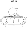
- Figure 13 is a schematic diagram of an image formation system adopting the intermediate transfer system according to prior art.
- a toner image T is formed on a latent image support drum 11 by a charger, an image exposure device, a developing device, etc., (not shown) disposed on the periphery of the latent image support drum 11 formed on the surface with a photosensitive substance.
- the toner image T has negative charge.
- An intermediate transfer medium belt 16 being placed on a drive roll 71 and a tension roll 17 rotating in the arrow C direction for turning in the arrow B direction is disposed approaching the latent image support drum 11.
- the toner image T formed on the latent image support drum 11 is transferred onto the intermediate transfer medium belt 16.
- a transfer charger 15 is provided on the rear side of transfer position P of the intermediate transfer medium belt 16 opposed to the latent image support drum 11 for supplying positive charge of polarity opposite to the toner image T to the intermediate transfer medium belt 16.
- the toner image T on the latent image support drum 11 is transferred onto the intermediate transfer medium belt 16 by the charge.
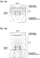
- Figures 14A and 14B are diagrammatic illustrations showing change of a potential distribution and an electric field distribution associated with change of a gap between the latent image support drum and the intermediate transfer medium belt.
- Figures 14A and 14B diagrammatically show the latent image support drum in the upper part toward the paper face and the intermediate transfer medium belt in the lower part and a gap and a toner layer transferred onto the intermediate transfer medium belt between the latent image support drum and the intermediate transfer medium belt.
- the potential distribution is represented as contour lines and the electric field distribution is represented by arrow directions. The arrows representing the electric field distribution are indicated only for both left and right ends and the center of the toner layer.
- Case 1 shown in Figure 14A indicates a state in which the latent image support drum and the intermediate transfer medium belt most approach each other just after toner is transferred from the latent image support drum to the intermediate transfer medium belt.
- Case 2 shown in Figure 14B indicates a state in which the latent image support drum and the intermediate transfer medium belt are set apart from each other as compared with Case 1 after the transfer.
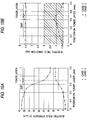
- Figures 15A and 15B are graphs showing the electric field state in the gap between the latent image support drum and the intermediate transfer medium belt.
- Figures 15A and 15B represent horizontal positions in Figures 14A and 14B on the uppermost layer face of a toner layer formed on the intermediate transfer medium belt in Figures 14A and 14B.
- the vertical axis of Figure 15A represents the electric field strength and that of Figure 15B represents the electric field directions.
- the portion hatched in Figure 15B indicates the range in which the electric field direction is a direction causing toner to scatter. Although the electric field direction is within the range, if the electric field strength is small (generally about several V/ ⁇ m or less), toner scattering does not occur due to action of adhesion force of toner to each other, gravity, etc.
- the electric field direction is almost ⁇ /2, namely, an upward direction perpendicular to the intermediate transfer medium belt surface (toner face); however, in case 2, the electric field direction is - ⁇ /2, reversed to a downward direction perpendicular to the intermediate transfer medium belt surface, and moreover the electric field strength increases as approaching the toner layer, and reaches about 10 V/ ⁇ m in the toner layer portion, thus showing that in Case 2, toner receives strong action in the direction in which it easily scatters.
- Japanese Patent Laid-Open No. Hei 3-267971 discloses a method of applying a bias reverse to a transfer bias upstream from a transfer position, thereby suppressing a transfer electric field.
- Japanese Patent Laid-Open No. Hei 4-186387 discloses a method of installing means for blocking an electric field turning upstream from a transfer position or weakening an electric field, thereby suppressing a transfer electric field and preventing toner from moving in a gap.
- Hei 2-163779 discloses a method of installing a conductive cover for shielding an electric field between a latent image support drum and a transfer roller upstream and downstream from a transfer position.
- a technique of providing a regulation plate upstream from a transfer corotron for preventing charge from flowing upstream from a transfer position is generally used.
- the remedies are all remedies for (1) or (2) and are not remedies against toner scattering as charge diminishes after transfer in (3).
- a first image formation system comprising a latent image support on which a latent image is formed, means for forming a latent image on the latent image support, means for developing the latent image formed on the latent image support in toner, thereby forming a toner image on the latent image support, an intermediate transfer medium for receiving transfer of the toner image formed on the latent image support, first transfer means for transferring the toner image formed on the latent image support to the intermediate transfer medium, force giving means for causing a force in an attraction direction toward the intermediate transfer medium to act on the toner image transferred onto the intermediate transfer medium, second transfer means for transferring the toner image transferred onto the intermediate transfer medium onto a predetermined recording medium, and fuser means for fixing the toner image transferred onto the recording medium on the recording medium.
- the second transfer means and the fuser means may be separate means; they may be a unit thereof for executing transfer and fixing.
- a second image formation system comprising a latent image support on which a latent image is formed, means for forming a latent image on the latent image support, means for developing the latent image formed on the latent image support in toner, thereby forming a toner image on the latent image support, means for transferring the toner image formed on the latent image support directly onto a predetermined recording medium or once onto a predetermined intermediate transfer medium and then onto the predetermined recording medium at a predetermined transfer position, fuser means for fixing the toner image transferred to the recording medium on the recording medium at a predetermined fixing position, means for transporting the recording medium along a predetermined transport passage through the predetermined transfer position and the predetermined fixing position, and force giving means for causing a force in an attraction direction toward the recording medium to act on the toner image transferred onto the recording medium between the predetermined transfer position and the predetermined fixing position on the predetermined transport passage.
- toner for making the toner image supports charge and the force giving means is electric field giving means for causing an electric field to act on the toner image, thereby giving the force in the attraction direction to the toner image.
- toner for making the toner image is magnetic substance and the force giving means is magnetic field giving means for causing a magnetic field to act on the toner image, thereby giving the force in the attraction direction to the toner image.
- the intermediate transfer medium may be made of a material to allow air to pass therethrough
- the force giving means may be air suction means for sucking air passing through the intermediate transfer medium from the rear side of the surface of the intermediate transfer medium onto which the toner image is transferred, thereby causing the force in the attraction direction to act on the toner image.
- Figure 1 is a schematic block diagram of a color image formation system to show one embodiment of a first image formation system of the invention.
- an image read section 2 for reading an image of an original document 4 is placed on the top of a color image formation system main unit 1. It comprises platen glass 3, a light source 5, two scanning mirrors 6 and 7, an image formation lens 8, a color CCD sensor 9, etc. A reflected light image from the original document 4 placed on the platen glass 3 and illuminated by the light source 5 is read through the two scanning mirrors 6 and 7 and the image formation lens 8 by the CCD sensor 9 as RGB image signals.
- the read RGB image signals are input to an image signal processing section 10 and are converted into YMCK image signals by the image signal processing section 10 and are temporarily stored in a memory provided in the image signal processing section 10 as required.
- the color image formation system main unit 1 contains an image formation unit 30 and an intermediate transfer medium unit 31.
- the image formation unit 30 comprises a drum-like latent image support drum 11 turning in the arrow A direction.
- the latent image support drum 11 is charged uniformly to a predetermined negative potential by a charger 12, then an electrostatic latent image is formed by a laser beam scanning section 13.
- the laser beam scanning section 13 radiates the latent image support drum 11 with a laser beam responsive to color image data of yellow (Y), magenta (M), cyan (C), and black (K) output in sequence from the image signal processing section 10, thereby exposing an image to light and resultantly forming an electrostatic latent image on the latent image support drum 11.
- the electrostatic latent image formed on the latent image support drum 11 is developed by developing devices 14a, 14b, 14c, and 14d for forming yellow (Y), magenta (M), cyan (C), and black (K) color toner images respectively. Tone of the colors is charged negative and deposited on the area on the latent image support drum 11 radiated with the laser beam. Each time the latent image support drum 11 turns once, a tone image of one color is formed and when the latent image support drum 11 turns four times, toner images of four colors are formed.
- the intermediate transfer medium unit 31 comprises an intermediate transfer medium belt 16 placed on a drive roll 71, a tension roll 17, idler rolls 18 and 20, and a secondary transfer backup roll 19.
- the intermediate transfer medium belt 16 is driven by the drive roll 71 and turns in the arrow B direction.
- the intermediate transfer medium belt 16 uses a polycarbonate resin whose resistant value is adjusted to about volume resistance 10 12 ⁇ cm, for example.
- a transfer charger 15 is provided on the rear side of the intermediate transfer medium belt 16 at a first transfer position P1 where the intermediate transfer medium belt 16 faces the latent image support drum 11 for supplying positive charge to the intermediate transfer medium belt 16.
- a toner image on the latent image support drum 11 is transferred onto the intermediate transfer medium belt 16 by the action of the charge on the intermediate transfer medium belt 16.
- a paper feed cassette 21 for storing recording media 23 and a fuser 26 are disposed on the bottom of the image formation system main unit 1.
- the intermediate transfer medium belt 16 After toner images of four colors are transferred onto the intermediate transfer medium belt 16, the intermediate transfer medium belt 16 furthermore turns for moving the toner images of four colors to a second transfer point P2. In synchronization with the toner images of four colors arriving at the second transfer point P2, one of the recording media 23 stored in the paper feed cassette 21 is fed by a paper feed roll 22 and is transferred to the second transfer position P2.
- a secondary transfer roll 24 is disposed facing the secondary transfer backup roll 19 for supplying positive charge to the recording medium 23.
- Toner image on the intermediate transfer medium belt 16 is electrostatically transferred onto the recording medium 23 by the action of the charge on the recording medium 23.
- the recording medium 23 onto which the toner image is transferred undergoes a fixing treatment by heat and under pressure by the fuser 26, then is discharged to a tray 27.
- the color image formation cycle is now complete.
- Residues on the surface of the latent image support drum 11 completing the transfer at the first transfer position P1 are removed by a cleaner 32, and the latent image support drum 11 makes the transition to the next image formation cycle.
- the intermediate transfer medium unit 31 is provided with electric field giving means 25 adjacent to the transfer charger 15 downstream from the first transfer position P1.
- the electric field giving means 25 forms an electric field in a direction from the rear side of the intermediate transfer medium belt 16 toward the surface side thereof for giving a force to the toner image transferred onto the intermediate transfer medium belt 16 in a direction in which the toner image is attracted to the intermediate transfer medium belt 16. That is, the electric field giving means 25 causes a force in the attraction direction toward the intermediate transfer medium belt 16 to act on the toner image transferred onto the intermediate transfer medium belt 16, thereby suppressing toner scattering.
- the electric field giving means will be discussed later in detail.
- Figure 2 is a schematic block diagram to show the embodiment of the second image formation system of the invention.
- an image formation system main unit 100 is an image formation system for forming a monochrome image. It basically differs from the color image formation system main unit 1 previously described with reference to Figure 1 in composition on and after the transfer step; they are almost the same in composition before the transfer step. That is, an image read section 2, an image signal processing section 10, and an image formation unit 30 disposed on the top of the image formation system main unit 100 are almost the same as those of the color image formation system main unit 1.
- composition and operation before the transfer step will not be discussed again, and the composition and operation of the image formation system main unit 100 on and after the transfer step will be discussed.
- a transfer charger 15 is disposed facing the latent image support drum 11, and electric field giving means 25 is disposed adjacent to the transfer charger 15 downstream from the transfer position P.
- a paper feed cassette 21 for storing recording media 23, a regist roll 28, paper transport rolls 102a-102c, a paper transporter 101, and a fuser 26 are disposed on the bottom of the image formation system main unit 100.
- one of the recording media 23 is taken out from the paper feed cassette 21 by a feed roll 22 and is transported via the regist roll 28 and the paper transport rolls 102a-102c to the transfer position P.
- the transfer charger 15 disposed on the rear side of the transport passage of the recording medium 23 at the transfer position P supplies positive charge to the recording medium 23, and toner image on the latent image support drum 11 is transferred onto the recording medium 23 by the action of the charge on the recording medium 23.
- the recording medium 23 upon completion of the transfer is transported to the fuser 26 in the arrow B direction by the paper transporter 101 disposed downstream from the transfer position P and the toner image transferred onto the recording medium 23 undergoes a fixing treatment by heat and under pressure by the fuser 26, then is discharged to a tray 27.
- the color image formation cycle is now complete.
- Residues on the surface of the latent image support drum 11 completing the transfer at the transfer position P are removed by a cleaner 32, and the latent image support drum 11 makes the transition to the next image formation cycle.
- the electric field giving means 25 disposed downstream from the transfer position P forms an electric field in a direction from the rear side of the recording medium 23 toward the surface side thereof for giving a force to the toner image transferred onto the recording medium 23 in a direction in which the toner image is attracted to the recording medium 23. That is, the electric field giving means 25 causes a force in the attraction direction toward the recording medium 23 to act on the toner image transferred onto the recording medium 23, thereby preventing toner from scattering.
- the toner image formed on the latent image support is directly transferred onto the recording medium;
- the second image formation system of the invention namely, the image formation system comprising force giving means for giving a force to the toner image transferred onto the recording medium is not limited to an image formation system for transferring a toner image formed on a latent image support directly onto a recording medium and can also be applied to an image formation system for once transferring a toner image formed on a latent image support directly onto a predetermined intermediate transfer medium and then transferring it onto a predetermined recording medium.
- force giving means for causing a force in the attraction direction toward the recording medium to act on the toner image is provided between the position at which the toner image once transferred onto the intermediate transfer medium is transferred onto the recording medium and the position at which it is fixed.
- Both the first and second image formation systems of the invention may be applied to an image formation system comprising an intermediate transfer medium for causing a force toward the intermediate transfer medium to act on the toner image once transferred onto the intermediate transfer medium and also causing a force toward a recording medium to act on the toner image transferred from the intermediate transfer medium onto the recording medium.
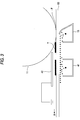
- Figure 3 is a schematic block diagram to show a first form of the force giving means.
- the latent image support drum 11 and the transfer charger 15 face each other with a transfer medium 60 such as a recording medium or an intermediate transfer medium moving in the arrow A direction between.
- An auxiliary charger 41 is disposed adjacent to the transfer charger 15 downstream from the transfer position P.
- a counter electrode 42 grounded is disposed on the opposite side to the position of the auxiliary charger 41 with the transfer medium 60 between.
- the auxiliary charger 41 supplies charge of the same polarity as the transfer charger 15 to the transfer medium 60 and an upward electric field is formed between the charge and the counter electrode 42.
- the auxiliary charger 41 and the counter electrode 42 serve as force giving means for causing a force in the attraction direction toward the transfer medium 60 to act on the toner image on the transfer medium 60, whereby toner is prevented from scattering.
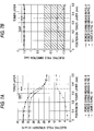
- Figures 4A and 4B are graphs showing the electric field state in a gap between the latent image support drum and the intermediate transfer medium belt of the force giving means shown in Figure 3.
- the horizontal axis of Figures 4A and 4B represents positions on the face of the uppermost toner layer and the vertical axis represents the electric field strength and the electric field directions.
- the curves indicated by solid lines in Figure 4A and 4B are the electric field strength and directions at the position of the auxiliary charger 41 shown in Figure 3.
- the curves indicated by broken lines are the electric field strength and directions in Case 2 in Figures 15A and 15B shown for reference.
- the auxiliary charger 41 and the counter electrode 42 are provided, whereby the electric field direction becomes upward and a force in the attraction direction to the transfer medium 60 acts on the toner image on the transfer medium 60, preventing toner from scattering.
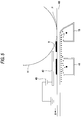
- Figure 5 is a schematic block diagram to show a second form of the force giving means.
- the force giving means comprises a power supply 43 for applying a bias voltage added to the counter electrode 42 in the force giving means shown in Figure 3.
- the auxiliary charger 41 is disposed adjacent to the transfer charger 15 downstream from the transfer position P where the latent image support drum 11 and the transfer charger 15 face each other with the transfer medium 60 moving in the arrow A direction between.
- the counter electrode 42 is disposed at the opposite position to the position of the auxiliary charger 41 with the transfer medium 60 between.
- the power supply 43 for applying a bias voltage is connected to the counter electrode 42.
- a bias of the same polarity as toner T is applied from the power supply 43 to the counter electrode 42, so that the upper electric field is furthermore strengthened and the toner scattering prevention effect of the force giving means with the auxiliary charger 41 and the counter electrode 42 is furthermore enhanced.
- the bias voltage applied to the auxiliary charger 41 can also be relatively lessened by applying the bias to the counter electrode 42.
- bias voltage may be applied to the counter electrode 42, thereby furthermore enhancing the effect of the auxiliary charger.
- Figure 6 is a schematic block diagram to show a third form of the force giving means.
- a rear side electrode 51 positively charged is disposed adjacent to the transfer charger 15 downstream from the transfer position P where the latent image support drum 11 and the transfer charger 15 face each other with the transfer medium 60 moving in the arrow A direction between. Further, a surface side electrode 52 is disposed at the opposite position to the position of the rear side charger 51 with the transfer medium 60 between.
- the potential of the surface side electrode 52 is set lower than that of the rear side electrode 51 (if toner used is of a positive polarity, the potential of the surface side electrode 52 is set higher than that of the rear side electrode 51).
- An electric field is formed in a direction from the rear side electrode 51 to the surface side electrode 52.
- the rear side electrode 51 and the surface side electrode 52 serve as force giving means for causing a force in the attraction direction toward the transfer medium 60 to act on the toner image on the transfer medium 60, whereby toner is prevented from scattering.
- Figures 7A and 7B are graphs showing the electric field state in a gap between the latent image support drum and the intermediate transfer medium belt of the force giving means shown in Figure 6.
- the horizontal axis of Figures 7A and 7B represents positions on the face of the uppermost toner layer and the vertical axis represents the electric field strength and the electric field directions.
- the curves indicated by solid lines in Figures 7A and 7B are the electric field strength and directions when the force giving means shown in Figure 6 is used.
- the curves indicated by broken lines are the electric field strength and directions in the force giving means shown in Figure 3.
- the curves indicated by dotted lines are the electric field strength and directions in Case 2 in Figure shown for reference.
- the force giving means in Figure 6 can also be provided with a power supply, whereby a bias of the same polarity as toner T can be applied to the surface side electrode 52 for furthermore strengthening the upper electric field.
- the bias voltage applied to the rear side electrode 51 can also be relatively lessened by applying the bias to the surface side electrode 52.
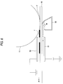
- Figure 8 is a schematic block diagram to show a fourth form of the force giving means.
- a transfer charger 15 having a width in a direction crossing the transfer medium move direction about 1.5 times the normal width is disposed downstream from the transfer position P where the toner image on the latent image support drum 11 is transferred onto the transfer medium 60 moving in the arrow A direction.
- the transfer charger 15 is thus widened, whereby it may also serve as a function of the force giving means for causing a force in the attraction direction toward the transfer medium 60 to act on the toner image T transferred onto the latent image support drum 11.
- the transfer current value is adjusted to a proper value in the force giving means in Figure 8, whereby almost the same effect as the force giving means in Figure 3 can be produced.
- a downstream shield 15a of the transfer charger 15 extends at least beyond a projection line 11a of the outer peripheral surface of the latent image support drum 11 onto the transfer medium 60.
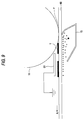
- Figure 9 is a schematic block diagram to show a fifth form of the force giving means.
- a counter electrode 61 grounded is disposed downstream from the transfer position P where the latent image support drum 11 and the transfer charger 15 face each other with the transfer medium 60 moving in the arrow A direction between, whereby charge from the transfer charger 15 is efficiently supplied to the transfer medium 60 downstream from the transfer position P, and almost the same effect as the surface electrode 52 in the force giving means shown in Figure 6 can be produced.
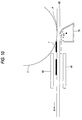
- Figure 10 is a schematic block diagram to show a sixth form of the force giving means.
- the force giving means is an example for forming images by using magnetic toner as toner for forming toner image T.
- a magnet 91 is disposed adjacent to the transfer charger 15 downstream from the transfer position P where the latent image support drum 11 and the transfer charger 15 face each other with the transfer medium 60 moving in the arrow A direction between.
- a magnet 92 is disposed at the opposite position to the magnet 91 with the transfer medium 60 between.
- a magnetic field formed by the pair of magnets 91 and 92 causes a force in the attraction direction toward the transfer medium 60 to act on magnetic toner image T transferred onto the transfer medium 60, so that toner is prevented from scattering.
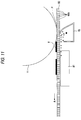
- Figure 11 is a schematic block diagram to show a seventh form of the force giving means.
- air suction means 81 is disposed adjacent to the transfer charger 15 downstream from the transfer position P where the latent image support drum 11 and the transfer charger 15 face each other with the transfer medium 60 moving in the arrow A direction between.
- the transfer medium 60 in the force giving means is limited to an intermediate transfer medium such as an intermediate transfer medium belt and does not include recording media such as paper.
- the transfer medium (intermediate transfer medium) is made of a breathing material having an unlimited number of fine holes 60a to allow air to path through.
- the air suction means 81 sucks air passing through the transfer medium 60 from the rear side of the face of the transfer medium 60 onto which toner image T is transferred, thereby causing a force in the attraction direction toward the transfer medium 60 to act on the toner image T, so that toner is prevented from scattering.
- the force giving means causes a force in the attraction direction toward the intermediate transfer medium to act on the toner image transferred onto the intermediate transfer medium, thus suppressing lowering the toner holding force of the intermediate transfer medium at a place where charge on the intermediate transfer medium diminishes just after the toner image is transferred. Resultantly, repellant of charges of toner is prevented from causing the toner to scatter and high-quality images can be provided.
- the force giving means disposed between a transfer position and a fixing position causes a force in the attraction direction toward a recording medium to act on the toner image transferred onto the recording medium, thus suppressing lowering the toner holding force of the recording medium at a place where charge on the recording medium diminishes just after the toner image is transferred. Resultantly, repellant of charges of toner is prevented from causing the toner to scatter and high-quality images can be provided.
Landscapes
- Physics & Mathematics (AREA)
- General Physics & Mathematics (AREA)
- Electrostatic Charge, Transfer And Separation In Electrography (AREA)
- Combination Of More Than One Step In Electrophotography (AREA)
Applications Claiming Priority (3)
| Application Number | Priority Date | Filing Date | Title |
|---|---|---|---|
| JP330528/95 | 1995-12-19 | ||
| JP7330528A JPH09171306A (ja) | 1995-12-19 | 1995-12-19 | 画像形成装置 |
| JP33052895 | 1995-12-19 |
Publications (2)
| Publication Number | Publication Date |
|---|---|
| EP0780736A2 true EP0780736A2 (de) | 1997-06-25 |
| EP0780736A3 EP0780736A3 (de) | 2000-10-18 |
Family
ID=18233649
Family Applications (1)
| Application Number | Title | Priority Date | Filing Date |
|---|---|---|---|
| EP96116270A Withdrawn EP0780736A3 (de) | 1995-12-19 | 1996-10-10 | Bilderzeugungssystem |
Country Status (3)
| Country | Link |
|---|---|
| US (1) | US5771432A (de) |
| EP (1) | EP0780736A3 (de) |
| JP (1) | JPH09171306A (de) |
Families Citing this family (6)
| Publication number | Priority date | Publication date | Assignee | Title |
|---|---|---|---|---|
| US6021302A (en) * | 1996-08-09 | 2000-02-01 | Agfa-Gevaert | Device for electrostatically transferring color toner images onto an electrically grounded receptor sheet |
| US6298212B1 (en) | 1999-09-14 | 2001-10-02 | Fuji Xerox Co., Ltd. | Apparatus providing improved image transfer to an intermediate transfer belt |
| US6327458B1 (en) | 2000-04-06 | 2001-12-04 | Lexmark International, Inc. | Method and apparatus for positioning paper in an imaging system having an intermediate transfer medium |
| KR100421032B1 (ko) * | 2002-06-29 | 2004-03-04 | 삼성전자주식회사 | 전자사진방식 인쇄기의 화상형성시스템 및 그를 이용한화상형성방법 |
| JP4877971B2 (ja) * | 2006-12-01 | 2012-02-15 | シャープ株式会社 | 画像形成装置 |
| JP7467873B2 (ja) * | 2019-10-08 | 2024-04-16 | コニカミノルタ株式会社 | 画像形成装置および画像形成方法 |
Family Cites Families (19)
| Publication number | Priority date | Publication date | Assignee | Title |
|---|---|---|---|---|
| US3966199A (en) * | 1975-03-17 | 1976-06-29 | Xerox Corporation | Belt transfer loading system |
| JPS5762066A (en) * | 1980-10-02 | 1982-04-14 | Canon Inc | Image recorder |
| JPS5834465A (ja) * | 1981-08-24 | 1983-02-28 | Canon Inc | 電子複写機の転写材案内装置 |
| JPS61100767A (ja) * | 1984-10-24 | 1986-05-19 | Canon Inc | 画像形成装置 |
| JPS61291344A (ja) * | 1985-06-18 | 1986-12-22 | Canon Inc | 転写材搬送装置 |
| JPS6457768A (en) * | 1987-08-28 | 1989-03-06 | Matsushita Electric Industrial Co Ltd | Manufacture of superconductor |
| US5140376A (en) * | 1988-03-15 | 1992-08-18 | Bando Chemical Industries, Ltd. | Transfer and conveying apparatus |
| JPH02163779A (ja) * | 1988-12-19 | 1990-06-25 | Canon Inc | 転写装置 |
| JPH0795212B2 (ja) * | 1989-02-14 | 1995-10-11 | シャープ株式会社 | トナー転写装置および中間転写装置 |
| JPH03267971A (ja) * | 1990-03-19 | 1991-11-28 | Canon Inc | 画像形成装置 |
| JP2727475B2 (ja) * | 1990-11-21 | 1998-03-11 | キヤノン株式会社 | 画像形成装置 |
| JPH06504855A (ja) * | 1991-02-05 | 1994-06-02 | オーセ プリンテイング システムズ ゲゼルシャフト ミット ベシュレンクテル ハフツング | 中間担体からトナー像を受取るために所属の静電的な装置を備えた、テープ状のトランスファ部材を有する印刷又はコピー装置 |
| JPH04345185A (ja) * | 1991-05-22 | 1992-12-01 | Canon Inc | 画像形成装置 |
| JPH0566689A (ja) * | 1991-09-10 | 1993-03-19 | Konica Corp | 画像形成装置 |
| US5223903A (en) * | 1992-04-20 | 1993-06-29 | Eastman Kodak Company | Sheet transport device for image-forming apparatus |
| EP0575947B1 (de) * | 1992-06-24 | 1997-12-17 | Matsushita Electric Industrial Co., Ltd. | Elektrophotographisches Farbegerät |
| JPH06274078A (ja) * | 1993-03-23 | 1994-09-30 | Minolta Camera Co Ltd | 画像形成装置 |
| JP3282886B2 (ja) * | 1993-06-28 | 2002-05-20 | 株式会社リコー | 中間転写方式を用いた画像形成装置 |
| JP3186372B2 (ja) * | 1993-10-13 | 2001-07-11 | 日立工機株式会社 | トナ−像記録装置 |
-
1995
- 1995-12-19 JP JP7330528A patent/JPH09171306A/ja active Pending
-
1996
- 1996-10-04 US US08/726,854 patent/US5771432A/en not_active Expired - Fee Related
- 1996-10-10 EP EP96116270A patent/EP0780736A3/de not_active Withdrawn
Also Published As
| Publication number | Publication date |
|---|---|
| US5771432A (en) | 1998-06-23 |
| EP0780736A3 (de) | 2000-10-18 |
| JPH09171306A (ja) | 1997-06-30 |
Similar Documents
| Publication | Publication Date | Title |
|---|---|---|
| US6952552B2 (en) | Image forming apparatus and method that applies different voltages to pressing members | |
| JPH0675437A (ja) | カラー画像の作成方法および装置 | |
| JPH02244170A (ja) | 画像形成装置 | |
| EP0571117A3 (de) | Kontrolle von Verunreinigungen für Berührungslose Entwicklung in einem xerographischen Gerät | |
| EP0377315B1 (de) | Bilderzeugungsgerät | |
| US5771432A (en) | Image formation system with toner scattering prevention | |
| US5038177A (en) | Selective pre-transfer corona transfer with light treatment for tri-level xerography | |
| JP3063155B2 (ja) | 画像形成装置の制御方法 | |
| US4640606A (en) | Corona discharger for separating copy paper from photoreceptor in electrophotographic copying machine | |
| JPH0419775A (ja) | 画像形成装置 | |
| EP1006416B1 (de) | Bilderzeugungsgerät | |
| US5784668A (en) | Image forming apparatus | |
| JP2629815B2 (ja) | 画像形成装置 | |
| JP3461215B2 (ja) | 画像形成装置 | |
| JP4211294B2 (ja) | 画像形成装置 | |
| JP3337294B2 (ja) | 電子写真装置 | |
| JP3023168B2 (ja) | 転写装置 | |
| JP2000137366A (ja) | 画像形成装置 | |
| JPH07248705A (ja) | 画像形成装置 | |
| JP2831682B2 (ja) | 画像記録装置の転写装置 | |
| JPH0365975A (ja) | 電子写真記録装置 | |
| JP3885721B2 (ja) | 画像形成装置 | |
| JP3016585B2 (ja) | 転写装置 | |
| JP3837956B2 (ja) | 画像形成装置 | |
| JP2752886B2 (ja) | トナー画像転写装置 |
Legal Events
| Date | Code | Title | Description |
|---|---|---|---|
| PUAI | Public reference made under article 153(3) epc to a published international application that has entered the european phase |
Free format text: ORIGINAL CODE: 0009012 |
|
| AK | Designated contracting states |
Kind code of ref document: A2 Designated state(s): DE FR GB |
|
| PUAL | Search report despatched |
Free format text: ORIGINAL CODE: 0009013 |
|
| AK | Designated contracting states |
Kind code of ref document: A3 Designated state(s): DE FR GB |
|
| 17P | Request for examination filed |
Effective date: 20001218 |
|
| 17Q | First examination report despatched |
Effective date: 20020102 |
|
| STAA | Information on the status of an ep patent application or granted ep patent |
Free format text: STATUS: THE APPLICATION IS DEEMED TO BE WITHDRAWN |
|
| 18D | Application deemed to be withdrawn |
Effective date: 20040501 |