EP0780948A1 - Vorrichtung zum radialen Aufweiten einer Elastomermuffe - Google Patents
Vorrichtung zum radialen Aufweiten einer Elastomermuffe Download PDFInfo
- Publication number
- EP0780948A1 EP0780948A1 EP96402767A EP96402767A EP0780948A1 EP 0780948 A1 EP0780948 A1 EP 0780948A1 EP 96402767 A EP96402767 A EP 96402767A EP 96402767 A EP96402767 A EP 96402767A EP 0780948 A1 EP0780948 A1 EP 0780948A1
- Authority
- EP
- European Patent Office
- Prior art keywords
- radial expansion
- members
- expansion
- expansion members
- sleeve
- Prior art date
- Legal status (The legal status is an assumption and is not a legal conclusion. Google has not performed a legal analysis and makes no representation as to the accuracy of the status listed.)
- Granted
Links
Images


Classifications
-
- H—ELECTRICITY
- H02—GENERATION; CONVERSION OR DISTRIBUTION OF ELECTRIC POWER
- H02G—INSTALLATION OF ELECTRIC CABLES OR LINES, OR OF COMBINED OPTICAL AND ELECTRIC CABLES OR LINES
- H02G15/00—Cable fittings
- H02G15/08—Cable junctions
- H02G15/18—Cable junctions protected by sleeves, e.g. for communication cable
- H02G15/182—Cable junctions protected by sleeves, e.g. for communication cable held in expanded condition in radial direction prior to installation
- H02G15/1826—Cable junctions protected by sleeves, e.g. for communication cable held in expanded condition in radial direction prior to installation on a removable hollow core, e.g. a tube
-
- B—PERFORMING OPERATIONS; TRANSPORTING
- B29—WORKING OF PLASTICS; WORKING OF SUBSTANCES IN A PLASTIC STATE IN GENERAL
- B29C—SHAPING OR JOINING OF PLASTICS; SHAPING OF MATERIAL IN A PLASTIC STATE, NOT OTHERWISE PROVIDED FOR; AFTER-TREATMENT OF THE SHAPED PRODUCTS, e.g. REPAIRING
- B29C55/00—Shaping by stretching, e.g. drawing through a die; Apparatus therefor
- B29C55/22—Shaping by stretching, e.g. drawing through a die; Apparatus therefor of tubes
- B29C55/24—Shaping by stretching, e.g. drawing through a die; Apparatus therefor of tubes radial
-
- B—PERFORMING OPERATIONS; TRANSPORTING
- B29—WORKING OF PLASTICS; WORKING OF SUBSTANCES IN A PLASTIC STATE IN GENERAL
- B29C—SHAPING OR JOINING OF PLASTICS; SHAPING OF MATERIAL IN A PLASTIC STATE, NOT OTHERWISE PROVIDED FOR; AFTER-TREATMENT OF THE SHAPED PRODUCTS, e.g. REPAIRING
- B29C63/00—Lining or sheathing, i.e. applying preformed layers or sheathings of plastics; Apparatus therefor
- B29C63/18—Lining or sheathing, i.e. applying preformed layers or sheathings of plastics; Apparatus therefor using tubular layers or sheathings
-
- H—ELECTRICITY
- H02—GENERATION; CONVERSION OR DISTRIBUTION OF ELECTRIC POWER
- H02G—INSTALLATION OF ELECTRIC CABLES OR LINES, OR OF COMBINED OPTICAL AND ELECTRIC CABLES OR LINES
- H02G1/00—Methods or apparatus specially adapted for installing, maintaining, repairing or dismantling electric cables or lines
- H02G1/14—Methods or apparatus specially adapted for installing, maintaining, repairing or dismantling electric cables or lines for joining or terminating cables
-
- B—PERFORMING OPERATIONS; TRANSPORTING
- B29—WORKING OF PLASTICS; WORKING OF SUBSTANCES IN A PLASTIC STATE IN GENERAL
- B29K—INDEXING SCHEME ASSOCIATED WITH SUBCLASSES B29B, B29C OR B29D, RELATING TO MOULDING MATERIALS OR TO MATERIALS FOR MOULDS, REINFORCEMENTS, FILLERS OR PREFORMED PARTS, e.g. INSERTS
- B29K2021/00—Use of unspecified rubbers as moulding material
Definitions
- the present invention relates to a device for radially expanding an elastomeric sleeve.
- Document GB 1,128,074 also discloses a device for radially expanding a sleeve of elastic material comprising a rigid cylindrical guide member intended to receive the sleeve to be expanded, and a single tubular radial expansion member adapted to slide on the guide member.
- This single expansion member causes the sleeve to expand from its initial diameter to its final diameter in a single operation. To cause satisfactory expansion, it is therefore necessary to use a hydraulic device, the implementation of which cannot be envisaged on a cable connection site.
- a device for radially expanding a sleeve of elastic material comprising a rigid cylindrical guide member and an expansion means adapted to slide on the guide member, characterized in that the means for expansion comprises at least two sets of rigid tubular radial expansion members which fit together.
- each set of expansion member can be placed inside the elastomeric sleeve by applying a small effort and ensuring a progressive expansion of the elastomeric sleeve the number of sets to be used being a function of the expansion as desired from the rest dimension of the elastomeric sleeve.
- the expansion members can be installed on a site and the loss of elasticity which previously resulted from the storage of the sleeve in the expanded state is therefore avoided.
- the innermost set comprises three radial expansion members adapted to be positioned in line with one another.
- the middle expansion member can then be set up in the factory so that the other expansion members can be set up on site by applying a lower force due to the short length of these expansion members. radial.
- the radial expansion device according to the invention is intended to be used in connection with an elastomeric sleeve 1 produced in the workshop, for example by molding.
- the elastomeric sleeve 1 comprises, in the vicinity of each of its ends, an annular flange 20 which extends slightly in projection.
- the device according to the invention comprises a rigid cylindrical guide member 2, for example a rigid plastic tube which has not been shown in section in FIG. 1 and which is preferably placed in the workshop by a slight fitting. by force so as to be retained in the elastomeric sleeve 1 during storage.
- the device also comprises a first set of radial expansion members generally designated at 3 and a second set of radial expansion members generally designated at 4.
- the first set of radial expansion members 3 comprises three members 'radial expansion, a central expansion member bearing the specific reference numeral 3.1 and two end expansion members bearing the specific reference numeral 3.2.
- the central expansion member 3.1 has an internal diameter slightly greater than the external diameter of the cylindrical guide member 2 and comprises at its ends conical parts 5.
- the radial expansion member 3.1 is preferably placed in workshop which allows to position it in the middle position of the elastomeric sleeve 1.
- this middle part of the elastomeric sleeve is intended to cover the part of larger diameter of the cable junction so that the loss of elasticity which may result from the storage of the elastomeric sleeve 1 is immaterial vis-à-vis the elastic tightening properties which are desired for the protective sleeve.
- the radial expansion members 3.2 have a conical end 6 complementary to a conical end 5 of the expansion member 3.1 so that during the installation of the expansion members 3.2 as will be indicated below, the expansion members 3.2 fit into the ends of the expansion member 3.1 and constitute therewith a member having a cylindrical external surface serving as a guide for the second set of expansion members 4.
- the second set of expansion members 4 comprises two expansion members each having a cylindrical internal surface of a diameter very slightly greater than the diameter of the external surface of the expansion members 3 of the first set, and a conical external surface generally designated in 7 and comprising several portions 7.1, 7.2, 7.3 and 7.4 of decreasing taper from one end of the expansion members 4. At the lower taper end of the expansion members 4 have a stop collar 8 projecting from the external surface 7 of the member expansion 4.
- the expansion members 4 further comprise locking members bearing the general reference numeral 14.
- Each of the locking members 14 is in the form of an elastic bar 15 having an end 16 fixed to the abutment flange 8 of an expansion member 4, and an opposite hook-shaped end 17.
- the locking members 14 extend in a longitudinal direction of the expansion members 4.
- a gripping tongue 18 extends projecting outwards.
- the bars 15 are fixed by any suitable means to the expansion member 4, for example by means of staples 19.
- the radial expansion device preferably comprises a base 9 which in this embodiment comprises a central positioning orifice 10 having a cylindrical surface with a diameter very slightly greater than the external diameter of the radial expansion members 3.2, and a positioning flange 11 concentric with the positioning orifice 10 and having an internal surface 12 having a diameter slightly greater than the external diameter of the stop flanges 8 of the radial expansion members 4. Stop lugs 13 s' extend radially inside the positioning orifice 10.
- the middle expansion member 3.1 of the first set of radial expansion members and the cylindrical guide member 2 are preferably placed in the workshop after having been placed in the elastomer sleeve 1 grease facilitating the placement of these organs. Slip fat remains thus accumulated in the conical parts formed by the internal surface of the elastomeric sleeve 1 in the vicinity of the ends of the radial expansion member 3.1.
- the base 9 is arranged on the ground, the radial expansion members 3.2 are covered with grease and are placed on the ends of the cylindrical guide member 2 then one of the expansion members 3.2 is engaged in the orifice 10 of the base 9.
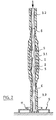
- the elastomer sleeve 1 and the radial expansion members are then arranged as illustrated in FIG. 2.
- a force is applied to the 'radial expansion member 3.2 opposite the base 9 as indicated by the arrow in thick lines in Figure 2, and the expansion members 3.2 penetrate inside the protective sleeve 1 causing a radial expansion thereof this.
- the guidance of the expansion members 3.2 facilitates their penetration inside the elastomeric sleeve 1.
- the expansion members 3.2 penetrate into the elastomeric sleeve 1 until their end conical parts fit into the corresponding conical parts of the radial expansion member 3.1 as illustrated in FIG. 3.
- the first set of expansion members 3 then produces a cylindrical assembly inside the elastomer sleeve 1 and in turn constitutes a guide for the second set of expansion members 4.
- the expansion members 4 are then put in place in a similar manner to the expansion members 3 by mounting these on the ends of the expansion members 3.2 extending projecting at the ends of the elastomeric sleeve 1 then by placing one of the stop flanges 8 in the positioning flange 11 of the base 9 and by exerting a force on the opposite end of the assembly thus produced.
- the decreasing taper of the conical portions of the external surface of the second set of expansion members which in the embodiment illustrated is the outermost set of expansion members, ensures sliding of the expansion members in the elastomeric sleeve 1 without scraping the grease which has previously been introduced into the sleeve.
- the stop flanges 8 are preferably disposed at a distance from the free ends corresponding to half the length of the elastomeric sleeve 1 so that it is ensured that the expansion members 4 penetrate symmetrically into the sleeve elastomer 1. During the introduction of the expansion members 4 the bars 15 engage opposite the external surface of the elastomer sleeve 1.
- Figure 4 illustrates the sectional view of the elastomeric sleeve 1 in the expanded position after removal of the cylindrical guide member 2 and Figure 5 illustrates the elastomeric sleeve 1 in the same position after removal of the first set of radial expansion members 3. It will be noted that there is then a large passage inside the radial expansion members 4 which allows the elastomeric sleeve 1 to be engaged on a cable and to bring the latter to a junction after the realization of it. An outward pull is then exerted on the gripping tabs 15 to release the hooks 17 from the flanges 20 of the elastomer sleeve 1.
- the radial expansion sleeves 4 can thus be removed, this removal being facilitated by the taper of the surface external of the radial expansion members 4.
- the removal of the radial expansion members 4 is preferably carried out symmetrically and thus allows progressive retraction of the elastomeric sleeve 1 by expelling the air bubbles towards the ends of the sleeve 1 and therefore avoiding trapping them under the elastomeric sleeve 1.
- the outermost radial expansion members here the second set of radial expansion members, not only have an expansion function but also a function of maintaining the expanded state of the elastomeric sleeve after removal of the innermost radial expansion organs.
- the outermost expansion sleeves 4 are preferably quite thin as illustrated in FIGS. 4 and 5 where the relative thicknesses have been better respected.
- locking members 14 have been shown in the form of elastic bars of substantially constant thickness, locking members could be provided articulated on a ring which is itself removably mounted on an expansion member so that the locking devices are reusable.
Landscapes
- Engineering & Computer Science (AREA)
- Mechanical Engineering (AREA)
- Manufacturing & Machinery (AREA)
- Cable Accessories (AREA)
- Insulating Bodies (AREA)
Applications Claiming Priority (2)
| Application Number | Priority Date | Filing Date | Title |
|---|---|---|---|
| FR9515046A FR2742597B1 (fr) | 1995-12-19 | 1995-12-19 | Dispositif d'expansion radiale d'un manchon elastomere |
| FR9515046 | 1995-12-19 |
Publications (2)
| Publication Number | Publication Date |
|---|---|
| EP0780948A1 true EP0780948A1 (de) | 1997-06-25 |
| EP0780948B1 EP0780948B1 (de) | 1999-11-03 |
Family
ID=9485641
Family Applications (1)
| Application Number | Title | Priority Date | Filing Date |
|---|---|---|---|
| EP96402767A Expired - Lifetime EP0780948B1 (de) | 1995-12-19 | 1996-12-17 | Vorrichtung zum radialen Aufweiten einer Elastomermuffe |
Country Status (5)
| Country | Link |
|---|---|
| EP (1) | EP0780948B1 (de) |
| DE (1) | DE69605015T2 (de) |
| ES (1) | ES2139320T3 (de) |
| FR (1) | FR2742597B1 (de) |
| PT (1) | PT780948E (de) |
Cited By (2)
| Publication number | Priority date | Publication date | Assignee | Title |
|---|---|---|---|---|
| KR100417497B1 (ko) * | 2001-12-05 | 2004-02-05 | 엘지전선 주식회사 | 전력 케이블의 외경에 고무 슬리브를 안착시키는 장치 |
| WO2007074481A1 (en) | 2005-12-28 | 2007-07-05 | Prysmian Cavi E Sistemi Energia S.R.L. | Method of disposing a tubular sleeve on a supporting element and apparatus to put said method into practice |
Families Citing this family (1)
| Publication number | Priority date | Publication date | Assignee | Title |
|---|---|---|---|---|
| FR2786954B1 (fr) * | 1998-12-02 | 2001-01-12 | Sagem | Dispositif de maintien en expansion d'un manchon elastique, et procede et dispositif de mise en expansion d'un manchon elastique |
Citations (3)
| Publication number | Priority date | Publication date | Assignee | Title |
|---|---|---|---|---|
| GB1128074A (en) | 1966-04-19 | 1968-09-25 | Stewarts & Lloyds Ltd | Cladding of joints in pipes or tubes |
| FR2503476A1 (fr) * | 1981-04-01 | 1982-10-08 | Fabrication Cables Elect Cie G | Procede de depose d'une gaine protectrice sur l'extremite d'un cable electrique et dispositif pour la mise en oeuvre de celui-ci |
| US4506430A (en) * | 1983-09-19 | 1985-03-26 | Panduit Corp. | Elastic cover applicator and method of applying cover |
-
1995
- 1995-12-19 FR FR9515046A patent/FR2742597B1/fr not_active Expired - Fee Related
-
1996
- 1996-12-17 EP EP96402767A patent/EP0780948B1/de not_active Expired - Lifetime
- 1996-12-17 PT PT96402767T patent/PT780948E/pt unknown
- 1996-12-17 DE DE69605015T patent/DE69605015T2/de not_active Expired - Fee Related
- 1996-12-17 ES ES96402767T patent/ES2139320T3/es not_active Expired - Lifetime
Patent Citations (3)
| Publication number | Priority date | Publication date | Assignee | Title |
|---|---|---|---|---|
| GB1128074A (en) | 1966-04-19 | 1968-09-25 | Stewarts & Lloyds Ltd | Cladding of joints in pipes or tubes |
| FR2503476A1 (fr) * | 1981-04-01 | 1982-10-08 | Fabrication Cables Elect Cie G | Procede de depose d'une gaine protectrice sur l'extremite d'un cable electrique et dispositif pour la mise en oeuvre de celui-ci |
| US4506430A (en) * | 1983-09-19 | 1985-03-26 | Panduit Corp. | Elastic cover applicator and method of applying cover |
Cited By (7)
| Publication number | Priority date | Publication date | Assignee | Title |
|---|---|---|---|---|
| KR100417497B1 (ko) * | 2001-12-05 | 2004-02-05 | 엘지전선 주식회사 | 전력 케이블의 외경에 고무 슬리브를 안착시키는 장치 |
| WO2007074481A1 (en) | 2005-12-28 | 2007-07-05 | Prysmian Cavi E Sistemi Energia S.R.L. | Method of disposing a tubular sleeve on a supporting element and apparatus to put said method into practice |
| AU2005339513B2 (en) * | 2005-12-28 | 2011-03-17 | Prysmian Cavi E Sistemi Energia S.R.L. | Method of disposing a tubular sleeve on a supporting element and apparatus to put said method into practice |
| CN101346860B (zh) * | 2005-12-28 | 2011-08-31 | 普雷斯曼电缆及系统能源有限公司 | 在支撑元件上布置管状套筒的方法和实施所述方法的设备 |
| US8273200B2 (en) | 2005-12-28 | 2012-09-25 | Prysmian Cavi E Sistemi Energia S.R.L. | Method of disposing a tubular sleeve on a supporting element and apparatus to put said method into practice |
| US8789570B2 (en) | 2005-12-28 | 2014-07-29 | Prysmian Cavi E Sistemi Energia S.R.L. | Apparatuses for disposing tubular covering sleeves for electric-cable joints on supporting elements |
| EP2506373A3 (de) * | 2005-12-28 | 2015-11-11 | Prysmian S.p.A. | Vorrichtung zum Aufschieben einer rohrförmigen Hülse auf ein Stützelement |
Also Published As
| Publication number | Publication date |
|---|---|
| FR2742597A1 (fr) | 1997-06-20 |
| DE69605015D1 (de) | 1999-12-09 |
| FR2742597B1 (fr) | 1998-01-23 |
| EP0780948B1 (de) | 1999-11-03 |
| PT780948E (pt) | 2000-04-28 |
| DE69605015T2 (de) | 2000-05-25 |
| ES2139320T3 (es) | 2000-02-01 |
Similar Documents
| Publication | Publication Date | Title |
|---|---|---|
| EP0497655B1 (de) | Radzierblende, insbesondere für Kraftfahrzeuge | |
| EP1064489B1 (de) | Steck-kupplung für rohre | |
| EP2183491B1 (de) | Vorrichtung zum anordnen von einem klemmring auf einem teil und automatisch ausgelöstes klemmsystem mit einer solchen vorrichtung | |
| FR2761830A1 (fr) | Support de jonction a extraction autonome commandee | |
| FR2493467A1 (fr) | Dispositif de raccordement hydraulique a accouplement rapide | |
| FR2654489A1 (fr) | Organe femelle de raccord de canalisation. | |
| FR2517016A1 (fr) | Raccord enclenchable pour tuyaux souples | |
| FR2669709A1 (fr) | Dispositif de raccord, notamment pour l'assemblage d'une durite a un echangeur de chaleur de vehicule automobile. | |
| FR2579716A1 (fr) | Raccord rapide | |
| WO2014207392A1 (fr) | Connecteur fluidique avec serrage de tube intégré. | |
| FR2669710A1 (fr) | Accouplement pour flexible, muni d'une piece tubulaire d'accouplement. | |
| EP1258666B1 (de) | Schnellkupplung mit Befestigung durch elastischen, äusseren Ring | |
| FR2617266A1 (fr) | Collier de serrage | |
| EP0006069A1 (de) | Spannbandartiges Befestigungselement | |
| FR2484050A1 (fr) | Dispositif de raccord pour tuyaux | |
| FR2868500A1 (fr) | Connecteur rapide | |
| EP1807648B1 (de) | Segmentierter klemmring und entsprechende anordnung und befestigungsverfahren | |
| EP0780948B1 (de) | Vorrichtung zum radialen Aufweiten einer Elastomermuffe | |
| EP1413815B1 (de) | Kupplung für zwei Rohre mit aufgeweiteten Enden | |
| FR2590648A1 (fr) | Dispositif de raccordement amovible d'une conduite | |
| FR2772875A1 (fr) | Dispositif de raccordement d'un tuyau souple a une paroi, en particulier d'un echangeur de chaleur de vehicule automobile | |
| FR2489472A1 (fr) | Dispositif de securite pour empecher le deplacement axial de liaisons par manchon de conduits tubulaires en matiere synthetique | |
| EP0441686A1 (de) | Vorrichtung zum dichten Verbinden von zwei identischen Rohren | |
| FR2554882A1 (fr) | Dispositif de fixation d'un cable bowden, en particulier pour equipements de chauffage ou de climatisation de voiture | |
| FR2468707A1 (fr) | Element de goulotte, et goulotte d'evacuation, notamment pour travaux de batiment, comportant une pluralite de tels elements |
Legal Events
| Date | Code | Title | Description |
|---|---|---|---|
| PUAI | Public reference made under article 153(3) epc to a published international application that has entered the european phase |
Free format text: ORIGINAL CODE: 0009012 |
|
| 17P | Request for examination filed |
Effective date: 19961218 |
|
| AK | Designated contracting states |
Kind code of ref document: A1 Designated state(s): BE CH DE ES FR GB LI LU PT |
|
| RAP1 | Party data changed (applicant data changed or rights of an application transferred) |
Owner name: SAGEM SA |
|
| GRAG | Despatch of communication of intention to grant |
Free format text: ORIGINAL CODE: EPIDOS AGRA |
|
| GRAG | Despatch of communication of intention to grant |
Free format text: ORIGINAL CODE: EPIDOS AGRA |
|
| GRAH | Despatch of communication of intention to grant a patent |
Free format text: ORIGINAL CODE: EPIDOS IGRA |
|
| 17Q | First examination report despatched |
Effective date: 19990329 |
|
| GRAH | Despatch of communication of intention to grant a patent |
Free format text: ORIGINAL CODE: EPIDOS IGRA |
|
| GRAA | (expected) grant |
Free format text: ORIGINAL CODE: 0009210 |
|
| AK | Designated contracting states |
Kind code of ref document: B1 Designated state(s): BE CH DE ES FR GB LI LU PT |
|
| REG | Reference to a national code |
Ref country code: CH Ref legal event code: EP |
|
| GBT | Gb: translation of ep patent filed (gb section 77(6)(a)/1977) |
Effective date: 19991103 |
|
| REF | Corresponds to: |
Ref document number: 69605015 Country of ref document: DE Date of ref document: 19991209 |
|
| PG25 | Lapsed in a contracting state [announced via postgrant information from national office to epo] |
Ref country code: LU Free format text: LAPSE BECAUSE OF NON-PAYMENT OF DUE FEES Effective date: 19991217 |
|
| REG | Reference to a national code |
Ref country code: ES Ref legal event code: FG2A Ref document number: 2139320 Country of ref document: ES Kind code of ref document: T3 |
|
| REG | Reference to a national code |
Ref country code: PT Ref legal event code: SC4A Free format text: AVAILABILITY OF NATIONAL TRANSLATION Effective date: 20000118 |
|
| PLBE | No opposition filed within time limit |
Free format text: ORIGINAL CODE: 0009261 |
|
| STAA | Information on the status of an ep patent application or granted ep patent |
Free format text: STATUS: NO OPPOSITION FILED WITHIN TIME LIMIT |
|
| 26N | No opposition filed | ||
| PG25 | Lapsed in a contracting state [announced via postgrant information from national office to epo] |
Ref country code: LI Free format text: LAPSE BECAUSE OF NON-PAYMENT OF DUE FEES Effective date: 20001231 Ref country code: CH Free format text: LAPSE BECAUSE OF NON-PAYMENT OF DUE FEES Effective date: 20001231 |
|
| REG | Reference to a national code |
Ref country code: CH Ref legal event code: PL |
|
| REG | Reference to a national code |
Ref country code: GB Ref legal event code: IF02 |
|
| REG | Reference to a national code |
Ref country code: GB Ref legal event code: 732E |
|
| REG | Reference to a national code |
Ref country code: FR Ref legal event code: TP |
|
| PGFP | Annual fee paid to national office [announced via postgrant information from national office to epo] |
Ref country code: PT Payment date: 20051212 Year of fee payment: 10 |
|
| PGFP | Annual fee paid to national office [announced via postgrant information from national office to epo] |
Ref country code: GB Payment date: 20051213 Year of fee payment: 10 |
|
| PGFP | Annual fee paid to national office [announced via postgrant information from national office to epo] |
Ref country code: ES Payment date: 20051214 Year of fee payment: 10 |
|
| PGFP | Annual fee paid to national office [announced via postgrant information from national office to epo] |
Ref country code: FR Payment date: 20051226 Year of fee payment: 10 |
|
| PGFP | Annual fee paid to national office [announced via postgrant information from national office to epo] |
Ref country code: BE Payment date: 20060102 Year of fee payment: 10 |
|
| PGFP | Annual fee paid to national office [announced via postgrant information from national office to epo] |
Ref country code: DE Payment date: 20060131 Year of fee payment: 10 |
|
| REG | Reference to a national code |
Ref country code: PT Ref legal event code: TE4A Owner name: SAFRAN, FR Effective date: 20061019 Ref country code: PT Ref legal event code: TE4A Owner name: SAGEM S.A., FR Effective date: 20061019 Ref country code: PT Ref legal event code: PD4A Owner name: SAFRAN, FR Effective date: 20061019 Ref country code: PT Ref legal event code: PC4A Owner name: SAGEM COMMUNICATION, FR Effective date: 20061019 |
|
| PG25 | Lapsed in a contracting state [announced via postgrant information from national office to epo] |
Ref country code: BE Free format text: LAPSE BECAUSE OF NON-PAYMENT OF DUE FEES Effective date: 20061231 |
|
| REG | Reference to a national code |
Ref country code: FR Ref legal event code: TP |
|
| PG25 | Lapsed in a contracting state [announced via postgrant information from national office to epo] |
Ref country code: PT Free format text: LAPSE BECAUSE OF NON-PAYMENT OF DUE FEES Effective date: 20070618 |
|
| REG | Reference to a national code |
Ref country code: PT Ref legal event code: MM4A Free format text: LAPSE DUE TO NON-PAYMENT OF FEES Effective date: 20070618 |
|
| PG25 | Lapsed in a contracting state [announced via postgrant information from national office to epo] |
Ref country code: DE Free format text: LAPSE BECAUSE OF NON-PAYMENT OF DUE FEES Effective date: 20070703 |
|
| GBPC | Gb: european patent ceased through non-payment of renewal fee |
Effective date: 20061217 |
|
| REG | Reference to a national code |
Ref country code: FR Ref legal event code: ST Effective date: 20070831 |
|
| PG25 | Lapsed in a contracting state [announced via postgrant information from national office to epo] |
Ref country code: GB Free format text: LAPSE BECAUSE OF NON-PAYMENT OF DUE FEES Effective date: 20061217 |
|
| BECA | Be: change of holder's address |
Owner name: *SAGEM COMMUNICATIONLE PONANT DE PARIS, 27 RUE LEB Effective date: 20060731 |
|
| BECH | Be: change of holder |
Owner name: *SAGEM COMMUNICATIONLE PONANT DE PARIS, 27 RUE LEB Effective date: 20060731 |
|
| BERE | Be: lapsed |
Owner name: *SAGEM COMMUNICATION Effective date: 20061231 |
|
| REG | Reference to a national code |
Ref country code: ES Ref legal event code: FD2A Effective date: 20061218 |
|
| PG25 | Lapsed in a contracting state [announced via postgrant information from national office to epo] |
Ref country code: FR Free format text: LAPSE BECAUSE OF NON-PAYMENT OF DUE FEES Effective date: 20070102 Ref country code: ES Free format text: LAPSE BECAUSE OF NON-PAYMENT OF DUE FEES Effective date: 20061218 |