EP0781724A2 - Système sychronisé d'ascenseur-navette - Google Patents
Système sychronisé d'ascenseur-navette Download PDFInfo
- Publication number
- EP0781724A2 EP0781724A2 EP96308661A EP96308661A EP0781724A2 EP 0781724 A2 EP0781724 A2 EP 0781724A2 EP 96308661 A EP96308661 A EP 96308661A EP 96308661 A EP96308661 A EP 96308661A EP 0781724 A2 EP0781724 A2 EP 0781724A2
- Authority
- EP
- European Patent Office
- Prior art keywords
- car
- landing
- cabs
- cab
- moving
- Prior art date
- Legal status (The legal status is an assumption and is not a legal conclusion. Google has not performed a legal analysis and makes no representation as to the accuracy of the status listed.)
- Withdrawn
Links
- 230000001360 synchronised effect Effects 0.000 title claims abstract description 21
- 238000000034 method Methods 0.000 claims description 17
- 230000003252 repetitive effect Effects 0.000 claims description 7
- 238000007599 discharging Methods 0.000 claims 1
- 238000010586 diagram Methods 0.000 description 5
- 230000008569 process Effects 0.000 description 4
- 238000002360 preparation method Methods 0.000 description 3
- 230000000694 effects Effects 0.000 description 2
- 239000007787 solid Substances 0.000 description 2
- 101100112084 Arabidopsis thaliana CRT2 gene Proteins 0.000 description 1
- 101100235014 Capsicum annuum LCY1 gene Proteins 0.000 description 1
- 238000007792 addition Methods 0.000 description 1
- 230000004075 alteration Effects 0.000 description 1
- 230000008859 change Effects 0.000 description 1
- 125000004122 cyclic group Chemical group 0.000 description 1
- 230000003247 decreasing effect Effects 0.000 description 1
- 230000003111 delayed effect Effects 0.000 description 1
- 230000006866 deterioration Effects 0.000 description 1
- 230000006698 induction Effects 0.000 description 1
- 230000000977 initiatory effect Effects 0.000 description 1
- 238000003801 milling Methods 0.000 description 1
- 230000004048 modification Effects 0.000 description 1
- 238000012986 modification Methods 0.000 description 1
- 230000009467 reduction Effects 0.000 description 1
- 230000004044 response Effects 0.000 description 1
- 230000002441 reversible effect Effects 0.000 description 1
Images


Classifications
-
- B—PERFORMING OPERATIONS; TRANSPORTING
- B66—HOISTING; LIFTING; HAULING
- B66B—ELEVATORS; ESCALATORS OR MOVING WALKWAYS
- B66B9/00—Kinds or types of lifts in, or associated with, buildings or other structures
-
- B—PERFORMING OPERATIONS; TRANSPORTING
- B66—HOISTING; LIFTING; HAULING
- B66B—ELEVATORS; ESCALATORS OR MOVING WALKWAYS
- B66B1/00—Control systems of elevators in general
- B66B1/24—Control systems with regulation, i.e. with retroactive action, for influencing travelling speed, acceleration, or deceleration
- B66B1/2408—Control systems with regulation, i.e. with retroactive action, for influencing travelling speed, acceleration, or deceleration where the allocation of a call to an elevator car is of importance, i.e. by means of a supervisory or group controller
- B66B1/2458—For elevator systems with multiple shafts and a single car per shaft
-
- B—PERFORMING OPERATIONS; TRANSPORTING
- B66—HOISTING; LIFTING; HAULING
- B66B—ELEVATORS; ESCALATORS OR MOVING WALKWAYS
- B66B1/00—Control systems of elevators in general
- B66B1/24—Control systems with regulation, i.e. with retroactive action, for influencing travelling speed, acceleration, or deceleration
- B66B1/2408—Control systems with regulation, i.e. with retroactive action, for influencing travelling speed, acceleration, or deceleration where the allocation of a call to an elevator car is of importance, i.e. by means of a supervisory or group controller
- B66B1/2491—For elevator systems with lateral transfers of cars or cabins between hoistways
-
- B—PERFORMING OPERATIONS; TRANSPORTING
- B66—HOISTING; LIFTING; HAULING
- B66B—ELEVATORS; ESCALATORS OR MOVING WALKWAYS
- B66B9/00—Kinds or types of lifts in, or associated with, buildings or other structures
- B66B9/003—Kinds or types of lifts in, or associated with, buildings or other structures for lateral transfer of car or frame, e.g. between vertical hoistways or to/from a parking position
-
- B—PERFORMING OPERATIONS; TRANSPORTING
- B66—HOISTING; LIFTING; HAULING
- B66B—ELEVATORS; ESCALATORS OR MOVING WALKWAYS
- B66B2201/00—Aspects of control systems of elevators
- B66B2201/30—Details of the elevator system configuration
- B66B2201/303—Express or shuttle elevators
-
- B—PERFORMING OPERATIONS; TRANSPORTING
- B66—HOISTING; LIFTING; HAULING
- B66B—ELEVATORS; ESCALATORS OR MOVING WALKWAYS
- B66B2201/00—Aspects of control systems of elevators
- B66B2201/30—Details of the elevator system configuration
- B66B2201/304—Transit control
-
- B—PERFORMING OPERATIONS; TRANSPORTING
- B66—HOISTING; LIFTING; HAULING
- B66B—ELEVATORS; ESCALATORS OR MOVING WALKWAYS
- B66B2201/00—Aspects of control systems of elevators
- B66B2201/30—Details of the elevator system configuration
- B66B2201/306—Multi-deck elevator cars
Definitions
- This invention relates to a high-traffic-volume, synchronous elevator shuttle system extending between three or more levels, with off-hoistway loading and unloading of passengers, and with full utilization of all hoistways.
- an elevator cab may be moved in a first car frame in a first hoistway, from the ground floor up to a transfer floor, moved horizontally into a second elevator car frame in a second hoistway, and moved therein upwardlv in the building, and so forth.
- the system of that application has a single cab transferring among multiple hoistways, the hoistways in which a cab is not currently being moved being idle, thus wasting core.
- Objects of the invention include provision of an elevator system which can extend between more than two levels, whereby to achieve moving passengers distances nearly double the distance limitation imposed by a roping system, that maximizes utilization of the hoistway, and that accommodates off-hoistway loading and unloading of passengers.
- an elevator system including at least two hoistways, each having a car frame moveable therein, and a plurality of horizontally moveable elevator cabs, simultaneously loads one cab from a landing onto a car frame and moves a cab from that car frame onto another car frame.
- a cab on the second car frame can also be moved, simultaneously with the others, to another landing.
- passengers are loaded into a cab before the cab is moved onto a car frame, and are unloaded from a cab after the cab is off loaded from a car frame.
- cabs are loaded at landings, moved to a car frame, the car frame is moved to another floor, the cab is moved to another car frame, and the cab is then moved to a third floor, whence it is moved to a landing for unloading.
- cabs are moved synchronously between landings in a fashion so that traffic is handled between a first and second level and between a second and third level, as well as between the first and third level, in both directions, on a regular basis; in further accord with the invention, the synchronized travel is so arranged that a cab leaving for a specific destination always leaves from the same origin landing and always arrives at the same destination landing.
- the cabs may be double deck cabs so that passengers leaving for a destination can leave from either of two landings, one immediately above the other, and always arrive at two corresponding landings, one above the other.
- double deck operation can be achieved so that a cab leaves for a given destination from an upper landing in between leaving for the same destination from a lower landing, on a repetitive cyclic basis.
- an elevator cab that is transferred through a multi-level multi-shaft system in a synchronized fashion always traces the same path from landing to landing to landing, etc., in a repetitive basis.
- the invention can be employed with three, four or more landings if desired.
- the invention achieves a very high utilization of each hoistway, particularly when operated in the double deck mode, and also permits frequent departures for any given destination from any given origin.
- the double deck embodiment is extremely useful in saving core with no deterioration of passenger service.
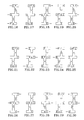
- Figs. 1-40 are simplified illustrations of the synchronized operation of a pair of shuttle elevators according to one embodiment of the invention.
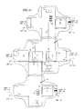
- Fig. 41 is a simplified, broken away side elevation view of the synchronized shuttle elevators described in Figs. 1-40.
- Figs. 42-46 are simplified illustrations of the synchronized operation of a pair of shuttle elevators according to one embodiment of the invention, when shutting the system down (e.g., before a weekend).
- Figs. 47-50 are simplified illustrations of the synchronized operation of a pair of shuttle elevators according to one embodiment of the invention, when starting the system up (e.g., after a weekend).
- Fig. 51 is a simplified illustration of the operation described in Figs. 1-40.
- Fig. 52 is a partial logic flow diagram illustrating a bank-synchronized modification to Fig. 54.
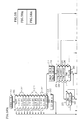
- Fig. 53 is a logic flow diagram of a car/cab control program to cause the synchronized shuttle elevators of Fig. 41 to operate in accordance with Figs. 1-40, and 42-52.
- Fig. 54 is a logic flow diagram of a car control subroutine for use in the routine of Fig. 53.
- Figs. 55-57 are logic flow diagrams of cab control subroutines for use in the routine of Fig. 53.
- Fig. 58 is a logic flow diagram of a transfer control subroutine for use in the routine of Fig. 53.
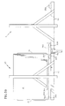
- Fig. 59 is a simplified, partially broken away, partially sectioned side elevation view of apparatus for effecting a transfer of elevator cabs, for use in the embodiment of Fig. 41.
- Figs. 60-65 are simplified illustrations of the synchronized operation of a pair of shuttle elevators according to another embodiment employing double decker elevators.
- Fig. 66 is a simplified illustration of the synchronized operation of four shuttle elevators according to another embodiment serving four levels.
- Fig. 67 is a simplified illustrations of the synchronized operation of nine shuttle elevators according to another embodiment with balanced service to four levels.
- a synchronized shuttle elevator system of one embodiment of the invention includes two elevators LO, HI, extending between three levels GND, MID, SKY of a building, each level having a right landing area R and a left landing area L, and having hoistway doors 70, the doors 70 for all of the left landing areas and the mid level right landing area being shown full to indicate that they are closed, and the hoistway doors 70 for the right landing areas of the sky level and the ground level being shown dotted to indicate they are open.
- Each elevator LO, HI includes a car having a car frame 72 suspended by a roping system 73 which is driven by a motor, sheave and brake system 74 along with a counterweight 75, in the usual fashion.
- the elevator car frames, as well as each entire elevator are referred to by their designations LO, HI, and are referred to simply as cars.
- Fig. 41 there are five elevator cabs A-E, each of which has elevator doors 76 on both the left (L) and right (R) sides.
- the elevator doors 76 for cabs A-C are shown solid, indicating they are closed.
- the right elevator doors for cabs D and E are shown dotted to indicate they are open, whereas the left elevator doors for these cabs are shown solid to indicate that they are closed.
- opening and closing of doors means the cab doors and the hoistway doors adjacent the car in question.
- a pair of arrows 71 indicate that the elevator cab doors and hoistway doors are open at the right landing area of the sky level and ground level; the arrows are utilized to illustrate that fact in Figs. 1-40, 42-51, and 60-67, as described hereinafter.
- Fig. 41 depicts cabs D and E at the sky and ground levels, with their doors open, allowing passengers to exchange between the cab and the landing.
- Fig. 41 also depicts cabs A-C being transferred toward the right: cab C is leaving the mid-level left landing (MID L) and boarding the car -frame 72 of the low elevator (LO); cab A is leaving the car frame 72 of the low elevator, crossing a sill 78 and entering onto the car frame 72 of the high elevator (HI); cab B is leaving the car frame 72 of the high elevator (HI) and entering onto the mid-level right landing (MID R). In a few seconds following the time depicted in Fig.
- cab B will be fully on the MID R landing (similar to cabs D and E in Fig. 41), cab C will be fully disposed on the LO car and cab A will be fully disposed on the HI car.
- the manner of transferring the cabs between the cars and landings is described with respect to Fig. 59 hereinafter.
- a cab leaving SKY L will always go to the mid-level (MID R, as described hereinafter), and so forth; a cab leaving SKY R will always travel to the ground level (GND R, as described hereinafter); this feature of the invention becomes more apparent with respect to Figs. 1-40 and 51.
- Fig. 1 The operation of the invention is described beginning in Fig. 1 with a condition where cab A is at the ground level in the low elevator; cab E is at the GND R landing; cab C is at the MID L landing; cab D is at the SKY R landing; and cab B is at the sky level in the HI car.
- each of Figures 1-40 depict actions, positions and conditions that occur in like numbered periods of the control clock. As is seen, in each of the odd numbered Figs.
- cab A has traveled upwardly and cab B has traveled downwardly so that both are at mid-level.
- the door to cab C closes and the doors to cabs D and E open.
- cabs C, A and B are all transferred to the right (as depicted in Fig. 41), and the doors to cabs D and E remain open.
- the doors to cab B are opened to allow passengers to emerge on the mid-level, while the doors to cab D and E are closed to prepare those cabs to be transferred.
- the door opening and closing occurs while cabs A and C are moving upwardly and downwardly in the high and low cars, respectively.
- cars A and D are transferred to the left at the sky level and cars C and E are transferred to the left at the ground level.
- the cars at the ground level and the sky level are transferred to the left at the same time and to the right at the same time, in each instance; in other embodiments, they need not be.
- the doors to cabs A and C are opened to allow passengers to emerge therefrom; the passengers emerging from cab A at the sky level are those that were in cab A at the ground level, as shown in Fig. 1.
- these passengers have traveled from the ground level to the mid-level in the LO car, transferred to the HI car, and then traveled upwardly in the HI car to the sky level.
- cab C The passengers emerging from cab C, on the other hand, are those that were entering the cab from the mid-level at the time depicted in Fig. 1.
- Fig. 6 the door to cab B closes in preparation for transferring cab B to the high car in Fig. 7 as cabs E, D and B are shifted to the left.
- cab A travels downwardly in the low elevator to the ground level, and then is shifted to the right along with cab C as depicted in Fig. 37; then the door to cab A opens allowing its passengers to exit as depicted in Fig. 38.
- Fig. 40 the doors to cab A are closed in preparation of being shifted to the right as depicted in Fig. 1, and described hereinbefore. Then the processes illustrated in Figs. 1-40 repeat, continuously, as long as the synchronized shuttle elevator system of the invention is in operation. As two of the cabs travel up or down, the other three cabs are standing at a landing with the doors open to allow exchange of passengers with the landings.
- each cab traverses the route illustrated in Fig. 52: GND-SKY; SKY-MID; MID-SKY; SKY-GND; GND-MID; MID-GND.
- shutting down the system is only permitted beginning with control period 34 by shutting off the service signs (e.g., serviceto ground LEVEL, Fig. 41); operation in control periods 34 and 35 is otherwise the same as shown in Figs. 34 and 35.
- Fig. 42 is identical to Fig. 36, except that as the door of cab D closes, it will be accompanied by an alarm and the absence of the service signs, so that no passengers should enter cab D at that time.
- control period 37 Operation in control period 37 is modified as shown in Fig. 43.
- cabs C and E are not released from the building and are therefore not transferred to the left as in Fig. 37; instead, cabs A and B are transferred to the left and cabs E and C remain in place at the sky right landing and the ground right landing, respectively.
- alarm is meant an irritating rasping noise that will scare people and cause them to not enter the elevator, as well as possibly having the lighting within the cab flickering or flashing on and off.
- control period 34 the service signs have been shut off in control period 34 in order to make it appear that the elevator is going out of service.
- the doors can close at very low speed with the lights off and the alarm on, if necessary, in order to coach passengers away from the cab.
- cabs C and E remain in place with their doors closed during control period 37.
- control period 38 the doors for cabs A and B open in order to allow the passengers to exit.
- the alarms will be on and the service signs will be off, as described for cabs C and E hereinbefore, so that passengers will not get on cabs A and B at this time.
- control period 39 as seen in Fig.
- cabs are standing still, cabs C, D and E have their doors closed, and cabs A and B have their doors open to permit passengers to exit, with the alarms on. Then in control period 0, as seen in Fig. 46, the doors for cabs A and B are closed, amidst alarms as described hereinbefore.
- the traction system motor and brake
- two cabs can be left on the car frames when shut down. In such a case, all the cabs must first be emptied without reloading, as described above, simply by passing through a pattern (e.g., all of Figs. 30-37) with alarms at each landing.
- control period 37 cabs C and E are transferred to the left; however, cabs A and B are already in the left position, and therefore are not transferred.
- control period 38 Fig. 50
- operation is exactly the same as during normal operation (as illustrated in Fig. 38). All of these operations are explained in more detail with respect to the controls therefor, hereinafter.
- a combined car/cab control routine determines whether service is normal, off, beginning or ending. It also calls the subroutines that perform the specialized synchronized control over the elevator cars and the cabs. The routine is reached through an entry point 100 and a first test 101 determines if the elevator management system (EMS) has requested the start-up of service in this two-elevator shuttle system, or not. If it has, a first step 102 sets a "start" flag and a second step 103 resets a "service off” flag.
- the control counter (described more fully hereinafter) is set to 35 by a step 104 so as to cause startup, beginning as described hereinbefore with respect to Fig. 47.
- a step 105 All of the service signs (legends, Fig. 41) are turned on by a step 105, and a step 106 resets the EMS request to start service. On the other hand, if the start of service has not been ordered by the EMS, a negative result of test 101 bypasses all of the steps 102-106.
- a test 107 determines if the EMS has ordered the end of service. If it has, a test 108 determines if the control is set to the 34th period. If it is, an affirmative result of test 108 reaches a step 109 which sets an "end" flag, a step 110 which turns off all the service signs, and a step 111 which resets the EMS request to end service.
- the control is at other than the 34th period, the end of service is not commenced since this embodiment utilizes a very simple process to assure that all passengers leave the cabs before the system is shut down.
- the invention may be practiced in a more complex system which recognizes any control period equivalent to period 34 and its relationship to the positioning of the cars.
- a test 112 determines if service has in fact been ended and is now off. If not, a number of subroutines are performed so as to control the processes described hereinbefore with respect to Figs. 1-51.
- a car control subroutine 113 controls the direction and running of the high and low elevator cars and locking them to the building at appropriate times.
- a transfer control subroutine 119 controls the transfer of the cabs from right to left and from left to right, in the manner described with respect to Figs. 1-42, hereinbefore.
- All of the subroutines 113-119 can be performed quite quickly, even though the task of each may not be accomplished in a single performance of the subroutine.
- the subroutines operate in the order of the car control first, then the cab controls and the transfer control last; but the order of actually performing the subroutines is irrelevant since they are fully interlocked with tests.
- an affirmative result of test 112 causes all of the subroutines 113-119 to be bypassed.
- other programming may be performed between any two of the subroutines 113-199, provided that each has a test similar to test 112 at the beginning thereof to bypass it when service is off. All of this is well within the skill of the art and irrelevant to the present invention.
- a first test 126 determines whether the start flag (step 102, Fig. 53) has been set or not. Under the assumption of normal operation, it has not been set, and a negative result of test 126 reaches a test 127 to determine if the end flag (step 109, Fig. 53) has been set or not. Under the assumption, it has not, so a negative result of test 127 reaches a test 128 to determine if the high and low elevators have been enabled to run yet or not.
- a negative result of test 128 reaches a test 129 to see if direction has been established for the low elevator, or not. Initially, it will not have, so a negative result of test 129 reaches a test 130 to see if there is a cab in the low elevator. If there is not, then this means that cabs are being transferred and not yet firmly in place on the elevator. Therefore, a negative result of test 130 causes other programming to be reverted to through a return point 133. In a subsequent pass through the subroutine of Fig.
- test 130 eventually a cab will be locked in place on the low car, and the interlock switch signal will indicate that a cab is in the low car. Then an affirmative result of the test 130 will reach a test 134 to determine if the control is set to any of the numbers for which the lowest two order bits are "10". This will occur for control periods 2, 6, 10, 14, etc. Reference to like numbered figures indicate that during these periods, the low car is at the ground level and its direction must be set to up, so that it can advance to the mid level. Therefore, an affirmative result of test 134 reaches a test 135 to verify that the position of the low car (determined by a well-known primary position transducer, or the like) indicates that the low car is at the ground level.
- a negative result of test 135 reaches a step 136 to set an error (designated as error two in this embodiment), and other programming is reverted to through the return point 133. It is assumed that setting of error two will cause other things to happen so that the subroutine of Fig. 54 is not reentered until the error is cleared up. On the other hand, if the low car is at the ground level, an affirmative result of test 135 will reach a step 138 to set the direction for the low car equal to up.
- test 134 determines whether the control is set to a number of which the two low order bits are "00". If not, then the system is not in a control period in which direction for the elevator cars is to be set. Therefore, a negative result of test 142 causes other programming to be reached through the return point 133. On the other hand, if the control is set at a number having low order bits "00", an affirmative result of test 142 reaches a test 143 to see if the low car is at the mid level, which it should be at the start of the 4th, 8th, 12th (and so forth) periods, as indicated in Figs. 4, 8, 12 and so forth.
- test 143 If it is not, a negative result of test 143 will reach step 136 to set the error. But if the low car is at the mid-level, then its next run must be down, so an affirmative result of test 143 reaches a step 144 to set the direction of the low car down.
- a test 142 is reached to see if direction has been set for the high car. If it has not, a negative result of test 142 reaches a series of steps and tests which are equivalent in all respects to the steps and tests 130-144 described hereinbefore for the low car, which require no further description.
- direction will have been established for both the low car and the high car so affirmative results of tests 129 and 146 reach a step 147 which sets a "run" flag. This causes the motion controller of the high car and the low car to cause the car to begin a run, in the direction established by the subroutine of Fig. 54. Once the "run" flag is set, each car will begin moving in an appropriate direction under the command of a car motion controller, in the usual fashion.
- the setting of "RUN” may be synchronized with a group controller, as shown in Fig. 52.
- a step 147a sets a "run ready car 1" flag, which the group controller can then return as an "enable run, car 1" flag, when the appropriate time arrives, which a test 147b responds to, to set the "run” flag and reset the "run ready, car 1" flag and the "enable run, car 1" flag.
- each subsequent pass through the subroutine of Fig. 54 will be similar until, finally, one or another of the cars reaches a leveling zone. If the low car reaches its leveling zone, an affirmative result of test 148 reaches a test 150 to see if the secondary position transducer (SPT) indicates that the low car is level with the landing which it is at. This is equivalent to the leveling that occurs at landings of ordinary elevators. If it is not level, a normal releveling subroutine 151 for the low elevator is reached to relevel the low elevator at its current landing. But if the SPT indicates that the low car is level with its landing, the subroutine 151 is bypassed.
- SPT secondary position transducer
- test 149 indicates that the high car is within its leveling zone
- a test 152 determines if the car is level. If it is not, it is releveled by a subroutine 153; otherwise, the subroutine 153 is bypassed. If the test 152 indicates the high car is level, then a test 158 determines if the low car is also level (note that test 149 can be reached without the low car being level). If both cars are level, an affirmative result of test 158 reaches a pair of tests 159, 160 to determine if both cars are totally stopped.
- steps 161 and 162 reset the lift brake command for both elevators, causing the brake to drop; steps 163 and 164 cause the low car and the high car to be locked to the floor of the building so that there will be no change in rope stretch as cabs are moved on and off the cars; steps 165 and 166 reset the direction for both the high car and the low car; a step 167 resets the "run” flag and a test 168 sets a "transfer” flag, indicating that cabs can now be transferred off the cars onto the landings, off the landings onto the cars, and between the cars.
- steps 161-168 have all been performed, indicating that cabs have been transported between levels on the cars and are ready for transfer, a step 169 increments the control to an odd number.
- Fig. 54 thus far is during normal operation. If the start flag has been set, an affirmative result of test 126 reaches a test 131 to determine if the control is set at 35. Initially it will be, since the control is set at 35 by step 104 (Fig. 53) to initiate operation. Therefore, an affirmative result of test 127 will reach a test 137 to determine if a delay time has been initiated or not. This is a period of time that will allow passengers sufficient time to enter cabs C and E (Fig. 47) before allowing the control to advance and close the doors to cabs C and E (Fig. 48). Normally, the doors will be open during the period of time in which the elevator cars make a round trip run, away from a level and then back to that level.
- test 101 will be negative
- test 107 will be negative
- test 112 will be negative once again reaching the car control subroutine 113 of Fig. 54.
- tests 126, 131 and 137 will be affirmative, reaching a test 145 to determine if the passenger timer has timed out or not. Initially, it will not have timed out, so other programming is reverted to through the return point 133. This will continue during many passes through the subroutine of Fig. 54 until finally a suitable time frame (on the order of 15 seconds) will have elapsed so that all of the passengers who wish to enter, have probably entered cabs C and E.
- test 145 When this happens, an affirmative result of test 145 reaches the step 169 which increments the controller so that it advances to control period 36. Referring to Fig. 48, this causes the doors of cabs C and E to be closed and the door of cab D to be opened.
- test 126 is affirmative but now test 131 is negative, reaching a test 154 to determine if the control is at 36; it will be, so an affirmative result of step 154 reaches step 169 where the control is again incremented because no car function is performed in control period 36. And then, other programming is reverted to through the return point 133.
- test 126 is affirmative, tests 131 and 154 are negative, and test 127 is negative. Then, operation is as described hereinbefore. That is, beginning with the control set to 37 (as in Fig. 49), the car control subroutine 113 operates the same during start as normally.
- test 137 is negative reaching steps 139 and 141 to initiate passenger delay timer, and set the flag. Since the control is incremented from even to odd within this subroutine, all subsequent passes through tests 170 and 171 will reach test 137, which is affirmative, awaiting timeout at test 145. Prior to timeout, a negative result of test 145 will always simply cause other programming to be reverted to through the return point 133, without incrementing the control in step 169. Once the passenger timer times out, an affirmative result of test 145 reaches step 169 to increment the control to period 39.
- an affirmative result of test 172 simply causes other programming to be reverted to through the return point 133, since there are no car control functions to be performed during the 39th control period when operation is ending.
- the transfer subroutine will cause a control to advance from 39 to 0 and an affirmative result of test 173 will simply bypass the remainder of the subroutine of Fig. 113 to the return point 133.
- all operation ceases in the first pass through the control transfer subroutine 119 when the operation is ending and the control is in the zero period.
- the cab control subroutine 114 for cab A is reached through entry point 174 and a pair of tests 175, 176 determine if the cab is at a landing and locked to the floor (in a manner described hereinafter, or not).
- the locking to the floor takes place in a different manner at a right landing than at a left landing.
- two different lock positions are used, one for the right and a different one for the left, so that the interlocking or safety that identifies the fact that the car is locked is different for the right than the left.
- This interlock may be no more than a microswitch which is closed only in response to full locking at the appropriate right or left position.
- a step 187 will cause the left door open command in cab A.
- a step 188 will cause a left door close command in cab A.
- a series of tests 191-193 determine if the control is set to a period requiring a right door open command in a step 197, and a series of tests 194-196 determine if a right door close command is required in a step 198.
- Figs. 12 and 14 show that the right hand door of cab A opens at control 12 and closes at control 14.
- the cab control subroutine 115 for cab B is identical to that for cab A except that the control periods tested in tests equivalent to tests 181-186 are 24, 30, 38, 26, 32 and 0, respectively. This can be seen by reference to Figs. of the same number: the cab B left door is opened in Figs. 24, 30 and 38 and closed in Figs. 26, 32 and 40. Similarly, the control numbers tested for in tests equivalent to tests 191-196 are 4, 10, 18, 6, 12 and 20 because it can be seen that the cab B right door is opened in Figs. 4, 10 and 18 and closed in Figs. 6, 12 and 20.
- the cab control routine 116 for cab C is the same as that for cab A except that the equivalent door numbers for the left doors are 0, 6, 14, 2, 8 and 16, the equivalent control numbers for the right doors are 20, 26, 34, 22, 28 and 36; and the alarm is turned on during an ending of normal operations in control period 34, and then turned off in control period 37.
- the cab control subroutine 118 for cab E is identical to that of cab C except the left door control numbers are 8, 14, 22, 10, 16 and 24; and the right door control numbers are 2, 28, 34, 4, 30 and 36.
- the alarm controls are identical.
- the cab control subroutine 117 for cab D is identical to the cab control subroutine 116 for cab C shown in Fig. 56 except for the control numbers involved.
- the left door control numbers are 16, 22, 30, 18, 24 and 32; the right door control numbers are 2, 10, 36, 4, 12 and 38.
- the alarms are turned on at control 36 and turned off at control 39, because as seen in Figs. 42 and 44, the right door of car D is open to let passengers out at control 36 and the door is closed at control 38.
- the transfer control subroutine 119 illustrated in Fig. 58, is reached through an entry point 207.
- a first test 208 determines if the transfer flag has been set in step 168 of Fig. 54. If it has not, then no horizontal movement of any of the cabs is to take place as a consequence of this pass through the subroutine 119.
- a negative result of test 208 reaches a test 209 to determine if end of normal operations is being established; in normal operation that is not the case, so a negative result of test 209 causes other programming to be reverted to through a return point 210.
- an affirmative result of test 208 reaches a series of tests 211 to determine if both the right and left doors are fully closed on all of the cabs A-E. If any of the doors are open, a negative result of the corresponding test 211 will cause other programming to be reverted to through the return point 210. In the normal case, all of the doors are closed so that affirmative results of all of the tests 211 will reach a test 212 to determine if the control is set odd. Normally it will be, because the control is incremented in step 169 of Fig. 54 from even to odd immediately following the setting of the transfer flag in step 168, except during startup and ending.
- test 212 determines if the control is set to a number ending in "001", which represents control numbers corresponding to Figs.
- both the high car and the low car have cabs shifting from left to right: that is, the cab on the car is shifted to a right landing and a cab on a left landing is shifted onto the car.
- a pair of steps 220, 221 unlock the cab in both the sky left landing and the ground left landing (these are cabs A and C in Fig. 8, for instance,) and then a step 222 commands a transfer to the right, which is effected in a manner described with respect to Fig. 59, hereinafter.
- a test 223 determines if a cab has been placed completely in the right sky landing (e.g., cab B, Fig. 9).
- a test 224 determines if a cab is fully positioned in the right ground landing. By this time, it usually will be and an affirmative result of test 224 reaches a step 225 where the cab is locked in the right ground landing (e.g., cab D, Fig. 9) by a step 226.
- test 219 determines if the control number is one which ends in "011". If so, this represents control numbers equal to Figs. 3, 11, 19, 27 and 35 in which the middle cab is shifted to the right. This causes a series of steps and tests 231-234 which, other than relating to the mid-level, are identical to steps and tests 221-224.
- test 230 determines if the control is set at a number ending in "101". If so, this relates to control numbers equivalent to Figs. 5, 13, 21, 29 and 37 in which the sky and ground cabs are shifted to the left. An affirmative result of test 235 reaches a test 236 to determine if the end flag is set or not. In the general case, it will not be so a negative result of test 236 reaches a series of steps and tests 240-246 which are respectively equivalent to tests and steps 220-226, except they relate to a transfer to the left. During the ending of normal operations, as is seen in Fig. 43, cabs A and B are shifted to the left, but cabs E and C are left behind.
- step 236 is affirmative and a step 247 indicates that the control is set at 37 (represented in Fig. 43).
- a step 247 indicates that the control is set at 37 (represented in Fig. 43).
- test 235 is negative, since test 212 indicates that the control is set to an odd number, the only remaining odd number is a control number ending in "111" which is equivalent to control numbers (and therefore Fig. numbers) 7, 15, 23, 31, and 39 in which the cabs at the mid-level are shifted to the left.
- a negative result of test 235 reaches a pair of tests 249, 250 to determine if the control is set at 39 and the end flag is set. If not, a negative result of either test 249 or 250 will reach a series of steps and tests 251-154 which correspond to the steps and tests 221-224 except that they relate to the cabs at the mid-level being shifted to the left. As can be seen by comparing Fig. 45 with Fig.
- the transfer control subroutine of Fig. 58 reaches a test 259 to see if the control is set at 39 or not. In the usual case, it is not so a negative result of test 259 reaches a step 260 to increment the control to the next higher number. Since the transfer control subroutine 119 runs during the odd cycles, the incrementing of step 260 causes the control to assume an even number. On the other hand, when test 259 is affirmative, then instead of incrementing, the control is reset to zero so as to repeat the functions illustrated in Figs. 1-40. And, each time test 259 is reached, step 258 will be reached to reset the transfer flag. After that, other programming is reverted to through the return point 210.
- any pass through the transfer control subroutine 119 whenever the transfer flag is not set, or a door is open, or the control is not set to an odd number, negative results of any of the tests 208, 211 or 212 will reach the test 209 to determine if the end flag is set in the process of ending normal operation. If the end flag is set, an affirmative result of test 209 reaches a test 259 to see if the control has reached zero or not. This will only happen in a pass through the subroutine immediately following the pass wherein affirmative results of tests 235 and 249 have caused step 257 to set the control to zero.
- test 209 and 259 reach a step 260 to reset the end flag, and a step 261 to set service off so that subsequent passes through the car cab control routine of Fig. 53 will bypass the subroutines 113-119 due to test 112 being affirmative.
- the cabs are moved simultaneously from landings to car frames, from car frames to car frames, and from car frames to landings.
- a preferred modality for transferring a cab between cars might be that disclosed in our European patent application claiming priority of U.S. patent application Serial No. 08/564,704 and filed contemporaneously herewith, as is described briefly with respect to Fig. 59.
- the bottom of the cab A has a fixed, main rack 350 extending from front to back (right to left in Fig. 59), and a sliding auxiliary rack 353 that can slide outwardly to the right, as shown, or to the left.
- an auxiliary motorized pinion 355 turns clockwise to drive the sliding auxiliary rack 353 out from under the cab into the position shown, where it can engage an auxiliary motorized pinion 356 on the platform 72, which is the limit that the rack 353 can slide. Then, the auxiliary motorized pinion 356 will turn clockwise pulling the auxiliary rack 353 (which now is extended to its limit) and therefore the entire cab A to the right as seen in Fig. 59 until such time as an end 357 of the main rack 350 engages a main motorized pinion (not shown) which is located just behind the auxiliary motorized pinion 356 in Fig. 59.
- auxiliary motorized pinion 359 can assist in moving the cab A to the right to another car frame or landing (if any).
- auxiliary pinion 360 can assist in moving a cab from a car frame or landing to the left of that shown in Fig. 59 (if any).
- the auxiliary pinion 356 will operate counterclockwise, causing the sliding, auxiliary rack 353 to move outwardly to the left until its left end 361 engages the auxiliary pinion 355. Then the auxiliary pinion 355 pulls the auxiliary rack 353 and the entire cab A to the left until the left end 362 of the main rack engages a main motorized pinion (not shown) located behind the auxiliary motorized pinion 355, which then pulls the entire cab to the left until it is fully on the car frame 72 of the LO elevator.
- a cab to leave each of the landings once every eight periods of the control, which is once for every four runs of the high and low elevator cars. Since each landing always is the beginning of a trip to a specific destination, a car begins each trip, once for each eight periods of the control (e.g., a passenger may leave the ground level for the sky level in car C in Fig. 8, in car E in Fig. 16, in car D in Fig. 24, and in car B in Fig. 32).
- a second embodiment of the invention provides that passengers may leave for any destination once for each four periods of the control, by utilizing double decker elevators, the upper and lower decks of which are not moved with the same timing, but rather the cabs in the upper deck are timed four control periods delayed from the movement of corresponding cars in the lower deck.
- This is illustrated in Figs. 60-65 wherein cabs V, W, X, Y and Z are deemed to be respectively equivalent to cabs A, B, C, D and E.
- the figure numbers in parentheses indicate the one of the figure numbers 1-40 which respectively illustrate the condition of one or the other sets of cabs. For instance, in Fig. 60, cabs A-E are in the same position as they are in Fig.
- cabs V-Z are in the same position that cabs A-E are in Fig. 37.
- Fig. 64 cabs V-Z are now in precisely the same position that cabs A-E are in Fig. 1.
- the second sets of cabs V-Z will be doing in any control period, what the first set of cabs A-E had done four control periods sooner.
- persons can leave the ground level for the sky level with the door closing during control period 0 (as in Fig. 40) in the lower deck within cab A, and may later leave the ground level for the sky level with the door closing in control period 4 within cab V of the upper deck.
- a level may comprise two floors of a building, or may only comprise a single floor with upper and lower landings at different heights on a related floor; or both.
- Typical timing for the present invention may include four seconds to transfer a car to the left, four seconds to transfer the car to the right, one-half second per story, so that if the mid-level is at the 80th floor and the sky level is at the 160th floor, the run time from one level to the other for each of the high and low elevators would be on the order of 40 seconds, giving a grand total trip time of 48 seconds to go from one level to an adjacent level. A total trip time from any level to the non-adjacent level requiring three shifts, would be on the order of 92 seconds.
- the travel time for a single elevator would be twice as long, that is on the order of 160 seconds so that service to which has to be added the time it takes to open the doors, allow passengers to exit and then allow the passenger to enter, which for large elevators may require 12 seconds per landing, pushing the total to over three minutes. (Check out the numbers and move to the front end).
- each car follows a repetitive, unique pattern of travel, and each car follows the same car throughout that path, and is followed by another same car throughout that path, indefinitely.
- the particular path is a consequence of how the cars are laid out when the system starts up. Referring to Fig. 1, if car C were at the right middle landing instead of the left middle landing, the result would be that the direction of the arrows in Fig. 51 would all reverse.
- the embodiment of the invention thus far is unique in that it provides the same service to all landings: that is, a trip to any particular landing begins on every other round trip cycle of the elevators. That is to say, a trip from the middle level left landing to the ground level left landing begins in Fig. 2, utilizing cab C, and the next trip begins in Fig. 10, utilizing cab E. Similarly, every other trip begins repetitively, once for each two round trips of the elevators.
- a second embodiment of the invention illustrated briefly in Figs. 60-65, will provide twice the service, with service leaving any level for any other level once for each round trip of the elevators.
- This embodiment uses double deck elevator cars and double decker landings at each level, in a manner consistent with the embodiment described thus far with respect to Figs. 1-59, and well-known double decker elevators.
- the upper deck system have its particular synchronization with respect to the control periods offset from the control period synchronization of the lower deck system by four control periods.
- Figs. 60-65 show the lower deck system being exactly the same as Figs. 1-6 hereinbefore.
- the upper deck system has the same condition as Fig. 1 hereinbefore in Fig. 64.
- Figs. 60-65 has the same dedicated service landings in both decks. That is, service from the ground level to the upper level begins at the left ground landings in both the upper and the lower deck; service from the ground level to the mid-level begins in the ground right landing of both the upper deck and the lower deck; and so forth. This simplifies the collection and guidance of passengers toward the correct landings depending upon their destinations.
- Figs. 66 and 67 illustrate another embodiment of the invention in which four levels can be served.
- the pattern illustrated in Fig. 66 advances in the next control period to the pattern illustrated in Fig. 67a.
- This pattern will provide, for each round trip of the elevators: service between the first and fourth level twice; service between the second and third level once; service between the third and first level twice; and service between the fourth and second level twice.
- Fig. 67b is shown the upside down version of the pattern in Fig. 67a.
- This pattern will provide, for each round trip of its elevators: service between the first and third levels twice; service between the second and fourth levels twice; service between the third and second levels once; and service between the fourth and first levels twice.
- a combination of the two systems, that shown in Fig. 67a as well as that shown in Fig. 67b, will provide combined service, for each round trip of all eight elevators as follows: level one to level three, twice; level one to level four, twice; level two to level three, once; level two to level four, twice; level three to level one, once; level four to level one, twice; level four to level two, twice. Therefore, a balanced system which provides two trip starts for any destination for each round trip of its elevators may be achieved by adding to the balanced set shown in illustrations a and b of Fig. 57, the five single level sets shown in illustration c, which will provide an additional single trip in each direction between levels two and three and two additional trips in each direction between levels one and two and levels three and four.
- Fig. 67 provides one trip beginning to any level once for each round trip of the elevators.
- the embodiment of Figs. 56 or 57 could be implemented with time-offset double deckers to provide trip starts for each start-up of an elevator.
- the invention may be utilized with other combinations of elevators, numbers of levels and numbers of cabs.
- the number of cabs equal the summation of the number of levels and the number of elevator cars, since in all of the even numbered control periods (of the embodiment of Figs. 1-40), there is one cab in each elevator and one cab left behind at each level.
Landscapes
- Engineering & Computer Science (AREA)
- Automation & Control Theory (AREA)
- Structural Engineering (AREA)
- Elevator Control (AREA)
- Types And Forms Of Lifts (AREA)
- Lift-Guide Devices, And Elevator Ropes And Cables (AREA)
Applications Claiming Priority (2)
| Application Number | Priority Date | Filing Date | Title |
|---|---|---|---|
| US564534 | 1995-11-29 | ||
| US08/564,534 US5651426A (en) | 1995-11-29 | 1995-11-29 | Synchronous elevator shuttle system |
Publications (2)
| Publication Number | Publication Date |
|---|---|
| EP0781724A2 true EP0781724A2 (fr) | 1997-07-02 |
| EP0781724A3 EP0781724A3 (fr) | 1998-06-03 |
Family
ID=24254864
Family Applications (1)
| Application Number | Title | Priority Date | Filing Date |
|---|---|---|---|
| EP96308661A Withdrawn EP0781724A3 (fr) | 1995-11-29 | 1996-11-29 | Système sychronisé d'ascenseur-navette |
Country Status (8)
| Country | Link |
|---|---|
| US (1) | US5651426A (fr) |
| EP (1) | EP0781724A3 (fr) |
| JP (1) | JPH09165148A (fr) |
| KR (1) | KR970026873A (fr) |
| CN (1) | CN1160011A (fr) |
| AU (1) | AU7198296A (fr) |
| CA (1) | CA2189919A1 (fr) |
| ZA (1) | ZA969381B (fr) |
Cited By (3)
| Publication number | Priority date | Publication date | Assignee | Title |
|---|---|---|---|---|
| WO2001087754A1 (fr) * | 2000-05-16 | 2001-11-22 | Otis Elevator Company | Algorithme de regulation d'ascenseur fonctionnant de maniere cyclique |
| WO2011007044A1 (fr) * | 2009-07-17 | 2011-01-20 | Kone Corporation | Agencement dascenseur et procédé permettant de déplacer une cabine dascenseur dans une cage dascenseur |
| WO2017023962A1 (fr) * | 2015-08-03 | 2017-02-09 | Otis Elevator Company | Poste de transfert intermédiaire |
Families Citing this family (30)
| Publication number | Priority date | Publication date | Assignee | Title |
|---|---|---|---|---|
| US5861586A (en) * | 1996-06-19 | 1999-01-19 | Otis Elevator Company | Horizontal and vertical passenger transport |
| US5816368A (en) * | 1997-03-20 | 1998-10-06 | Otis Elevator Company | Elevator cars switch hoistways while traveling vertically |
| US6520295B1 (en) * | 2000-05-16 | 2003-02-18 | Otis Elevator Company | Piston-type passenger conveying system |
| CN1298605C (zh) * | 2002-07-11 | 2007-02-07 | 株式会社日立制作所 | 电梯装置 |
| ES2373726T3 (es) * | 2005-02-04 | 2012-02-08 | Otis Elevator Company | Avisos indicando que una cabina está esperando a otra cabina en el mismo hueco de ascensor. |
| KR100946353B1 (ko) * | 2005-02-04 | 2010-03-08 | 오티스 엘리베이터 컴파니 | 승강로 내의 2 대의 카 중 어느 한 쪽에 부과되는 지연을최소화시키기 위하여 상기 2 대의 카 중 하나의 카에할당되는 호출들 |
| CN101568482B (zh) * | 2006-12-22 | 2013-12-25 | 奥蒂斯电梯公司 | 在单个井道中具有多个车厢的电梯系统 |
| CN102408054B (zh) * | 2011-08-21 | 2013-09-25 | 冯静 | 多层住宅楼的多幢楼共用电梯的建筑结构及使用方法 |
| CN105329745B (zh) * | 2012-04-26 | 2017-12-08 | 铰接细索列车公司 | 铰接细索列车 |
| WO2014158127A1 (fr) * | 2013-03-25 | 2014-10-02 | Otis Elevator Company | Système d'ascenseurs autopropulsés multi-cabines |
| DE102014201804A1 (de) * | 2014-01-31 | 2015-08-06 | Thyssenkrupp Elevator Ag | Verfahren zum Betreiben eines Aufzugsystems |
| US9758347B2 (en) | 2014-12-02 | 2017-09-12 | ThyssenKrupp Elevator AG; ThyssenKrupp AG | Arrangement and method to move at least two elevator cars independently in at least one hoistway |
| US20180029832A1 (en) * | 2015-02-05 | 2018-02-01 | Otis Elevator Company | Vehicle and method for elevator system installation |
| US10017354B2 (en) * | 2015-07-10 | 2018-07-10 | Otis Elevator Company | Control system for multicar elevator system |
| US9598265B1 (en) * | 2015-09-28 | 2017-03-21 | Smart Lifts, Llc | Vertically and horizontally mobile elevator cabins |
| US10472206B2 (en) * | 2015-12-04 | 2019-11-12 | Otis Elevator Company | Sensor failure detection and fusion system for a multi-car ropeless elevator system |
| JP6531642B2 (ja) * | 2015-12-24 | 2019-06-19 | 株式会社ダイフク | 物品搬送設備 |
| US10966936B2 (en) | 2015-12-30 | 2021-04-06 | Corium, Inc. | Systems comprising a composite backing and methods for long term transdermal administration |
| US20170355562A1 (en) * | 2016-06-10 | 2017-12-14 | Otis Elevator Company | Fire service sequence for multicar elevator systems |
| CN106335829A (zh) * | 2016-11-10 | 2017-01-18 | 山东建筑大学 | 一种移动对接立体式连通电梯 |
| US10081513B2 (en) * | 2016-12-09 | 2018-09-25 | Otis Elevator Company | Motion profile for empty elevator cars and occupied elevator cars |
| CN107032221A (zh) * | 2017-05-09 | 2017-08-11 | 绳季清 | 直线蜗轮电梯 |
| CN106927337A (zh) * | 2017-05-09 | 2017-07-07 | 绳季清 | 高层建筑双通道直线蜗轮电梯井道 |
| DE102017110275A1 (de) * | 2017-05-11 | 2018-11-15 | Thyssenkrupp Ag | Aufzugssystem mit zwei Schächten |
| CN107285167B (zh) * | 2017-07-31 | 2019-04-05 | 山东建筑大学 | 一种可垂直和横向移动的电梯 |
| DE102017219146A1 (de) * | 2017-10-25 | 2019-04-25 | Thyssenkrupp Ag | Aufzuganlage mit Schachtwechseleinheiten sowie Verfahren zum Betreiben einer Aufzuganlage mit Schachtwechseleinheiten |
| DE102018120386A1 (de) * | 2018-08-21 | 2020-02-27 | Thyssenkrupp Ag | Aufzugsystem mit einem ersten Teilaufzugsystem und einem zweiten Teilaufzugsystem |
| CN111252647B (zh) * | 2020-03-11 | 2021-09-03 | 天津优视津阳金属制品有限公司 | 一种三厢双层停靠式电梯 |
| JP7743818B2 (ja) * | 2022-07-01 | 2025-09-25 | 株式会社ダイフク | 物品収容設備 |
| CN115123317B (zh) * | 2022-07-19 | 2024-03-08 | 南京轨道交通产业发展有限公司 | 一种带电磁阀机械互锁结构的司控器控制电路 |
Family Cites Families (10)
| Publication number | Priority date | Publication date | Assignee | Title |
|---|---|---|---|---|
| US1580310A (en) * | 1924-09-17 | 1926-04-13 | Daniel F Lepley | Removable elevator cage |
| US1939729A (en) * | 1930-01-29 | 1933-12-19 | Thomas W Cohill | Elevator system |
| US2052690A (en) * | 1934-08-03 | 1936-09-01 | John T Austin | Elevator |
| US2626721A (en) * | 1945-04-25 | 1953-01-27 | Armitage & Bertram Ltd | Unloading system for mines |
| DE1912520A1 (de) * | 1969-03-12 | 1970-09-17 | Foerster Dr Med Hans Rudolf | Fahrstuhlsystem fuer schnellen Massenverkehr,insbesondere in Hochhaeusern |
| US3750849A (en) * | 1970-04-21 | 1973-08-07 | Westinghouse Electric Corp | Duplex counterweightless shuttle elevator system |
| US3658155A (en) * | 1970-09-15 | 1972-04-25 | William G Salter | Elevator system |
| DE2154923A1 (de) * | 1971-11-04 | 1973-05-10 | Adolf H Borst | Personenaufzug |
| DE69021417T2 (de) * | 1989-03-20 | 1996-04-04 | Hitachi Elevator Eng | Personenbeförderungseinrichtung. |
| JPH04361968A (ja) * | 1991-06-11 | 1992-12-15 | Mitsubishi Electric Corp | エレベーター装置 |
-
1995
- 1995-11-29 US US08/564,534 patent/US5651426A/en not_active Expired - Lifetime
-
1996
- 1996-11-07 ZA ZA969381A patent/ZA969381B/xx unknown
- 1996-11-08 CA CA002189919A patent/CA2189919A1/fr not_active Abandoned
- 1996-11-25 KR KR1019960057164A patent/KR970026873A/ko not_active Withdrawn
- 1996-11-26 AU AU71982/96A patent/AU7198296A/en not_active Abandoned
- 1996-11-28 CN CN96121364A patent/CN1160011A/zh active Pending
- 1996-11-29 EP EP96308661A patent/EP0781724A3/fr not_active Withdrawn
- 1996-11-29 JP JP8319338A patent/JPH09165148A/ja not_active Withdrawn
Cited By (7)
| Publication number | Priority date | Publication date | Assignee | Title |
|---|---|---|---|---|
| WO2001087754A1 (fr) * | 2000-05-16 | 2001-11-22 | Otis Elevator Company | Algorithme de regulation d'ascenseur fonctionnant de maniere cyclique |
| US6481535B1 (en) | 2000-05-16 | 2002-11-19 | Otis Elevator Company | Dispatching algorithm for piston-type passenger conveying system |
| AU2001261453B2 (en) * | 2000-05-16 | 2005-10-27 | Otis Elevator Company | Dispatching algorithm for cyclicly operating elevator |
| KR100761186B1 (ko) * | 2000-05-16 | 2007-09-21 | 오티스 엘리베이터 컴파니 | 탑승자 이동 시스템을 조작하는 방법 및 탑승자 이동 시스템 |
| WO2011007044A1 (fr) * | 2009-07-17 | 2011-01-20 | Kone Corporation | Agencement dascenseur et procédé permettant de déplacer une cabine dascenseur dans une cage dascenseur |
| WO2017023962A1 (fr) * | 2015-08-03 | 2017-02-09 | Otis Elevator Company | Poste de transfert intermédiaire |
| US10865072B2 (en) | 2015-08-03 | 2020-12-15 | Otis Elevator Company | Intermediate transfer station |
Also Published As
| Publication number | Publication date |
|---|---|
| JPH09165148A (ja) | 1997-06-24 |
| CA2189919A1 (fr) | 1997-05-30 |
| AU7198296A (en) | 1997-06-12 |
| US5651426A (en) | 1997-07-29 |
| CN1160011A (zh) | 1997-09-24 |
| ZA969381B (en) | 1997-06-02 |
| EP0781724A3 (fr) | 1998-06-03 |
| KR970026873A (ko) | 1997-06-24 |
Similar Documents
| Publication | Publication Date | Title |
|---|---|---|
| US5651426A (en) | Synchronous elevator shuttle system | |
| US5758748A (en) | Synchronized off-shaft loading of elevator cabs | |
| US7537089B2 (en) | Elevator installation with individually movable elevator cars and method for operating such an elevator installation | |
| RU2283270C2 (ru) | Система лифтов | |
| FI111929B (fi) | Hissiryhmän ohjaus | |
| EP0388814A2 (fr) | Equipement de transport de personnes | |
| US20060011420A1 (en) | Elevator installation with at least three vertical elevator shafts arranged adjacent to one another and method for operating such a elevator shaft | |
| EP0342008B1 (fr) | Système de réponses relatives pondérées pour système d'attribution de cabines d'ascenseurs | |
| MXPA03004344A (es) | Instalacion de ascensores con varias cabinas autopropulsadas y como minimo tres cajas de ascensor dispuestas una junto a otra. | |
| JPH1067471A (ja) | ローカルエレベータを備えたシャトルエレベータ | |
| EP0776850A2 (fr) | Cabines d'ascenseur transférées horizontalement entre des ascenseurs à double ponts | |
| US5655625A (en) | Emergency elevator cab commandeering shuttle | |
| US6505712B2 (en) | Device and method for control of double deck elevator system | |
| US5752585A (en) | Elevator shuttle with auxiliary elevators at terminals | |
| EP0776852A1 (fr) | Navette d'ascenseur utilisant une cabine transférable horizontalement | |
| US4401190A (en) | Cars/floors and calls/cars elevator assignments | |
| US5829553A (en) | Fail-safe movement of elevator cabs between car frames and landings | |
| HK1001204A (en) | Synchronous elevator shuttle system | |
| US5107962A (en) | Vertical transport system in a building | |
| US5749441A (en) | Extra deck elevator shuttle | |
| JPH09165147A (ja) | エレベータシャトルの分配発車システム及び分配発車方法 | |
| JP2001233553A (ja) | ダブルデッキエレベータの制御装置 | |
| HK1006255A (en) | Synchronized off-shaft loading of elevator cabs | |
| CN119306090B (zh) | 用于运送机器人的电梯 | |
| JPH1087232A (ja) | ロープ無しエレベータ装置およびその制御方法 |
Legal Events
| Date | Code | Title | Description |
|---|---|---|---|
| PUAI | Public reference made under article 153(3) epc to a published international application that has entered the european phase |
Free format text: ORIGINAL CODE: 0009012 |
|
| AK | Designated contracting states |
Kind code of ref document: A2 Designated state(s): DE FR GB |
|
| PUAL | Search report despatched |
Free format text: ORIGINAL CODE: 0009013 |
|
| AK | Designated contracting states |
Kind code of ref document: A3 Designated state(s): DE FR GB |
|
| 17P | Request for examination filed |
Effective date: 19981126 |
|
| STAA | Information on the status of an ep patent application or granted ep patent |
Free format text: STATUS: THE APPLICATION HAS BEEN WITHDRAWN |
|
| 18W | Application withdrawn |
Withdrawal date: 20011018 |
|
| REG | Reference to a national code |
Ref country code: HK Ref legal event code: WD Ref document number: 1001204 Country of ref document: HK |