EP0782027A2 - Microscope confocal à balayage - Google Patents
Microscope confocal à balayage Download PDFInfo
- Publication number
- EP0782027A2 EP0782027A2 EP97200380A EP97200380A EP0782027A2 EP 0782027 A2 EP0782027 A2 EP 0782027A2 EP 97200380 A EP97200380 A EP 97200380A EP 97200380 A EP97200380 A EP 97200380A EP 0782027 A2 EP0782027 A2 EP 0782027A2
- Authority
- EP
- European Patent Office
- Prior art keywords
- light
- microscope
- fibre
- scanning
- optical
- Prior art date
- Legal status (The legal status is an assumption and is not a legal conclusion. Google has not performed a legal analysis and makes no representation as to the accuracy of the status listed.)
- Granted
Links
- 230000003287 optical effect Effects 0.000 claims abstract description 49
- 238000005286 illumination Methods 0.000 claims abstract description 10
- 239000000835 fiber Substances 0.000 claims description 41
- 239000013307 optical fiber Substances 0.000 claims description 40
- 230000005540 biological transmission Effects 0.000 claims description 15
- 230000008878 coupling Effects 0.000 claims description 3
- 238000010168 coupling process Methods 0.000 claims description 3
- 238000005859 coupling reaction Methods 0.000 claims description 3
- 230000004044 response Effects 0.000 claims description 3
- 230000004048 modification Effects 0.000 description 4
- 238000012986 modification Methods 0.000 description 4
- 230000004075 alteration Effects 0.000 description 3
- 230000008901 benefit Effects 0.000 description 3
- 238000010226 confocal imaging Methods 0.000 description 3
- 238000000926 separation method Methods 0.000 description 3
- 235000014676 Phragmites communis Nutrition 0.000 description 2
- 238000010276 construction Methods 0.000 description 2
- 238000001514 detection method Methods 0.000 description 2
- 238000000034 method Methods 0.000 description 2
- 230000001360 synchronised effect Effects 0.000 description 2
- 238000001069 Raman spectroscopy Methods 0.000 description 1
- 239000006096 absorbing agent Substances 0.000 description 1
- 201000009310 astigmatism Diseases 0.000 description 1
- 208000002925 dental caries Diseases 0.000 description 1
- 210000003298 dental enamel Anatomy 0.000 description 1
- 210000004268 dentin Anatomy 0.000 description 1
- 238000001839 endoscopy Methods 0.000 description 1
- 238000005516 engineering process Methods 0.000 description 1
- 239000012530 fluid Substances 0.000 description 1
- 238000003384 imaging method Methods 0.000 description 1
- 230000004941 influx Effects 0.000 description 1
- 239000007788 liquid Substances 0.000 description 1
- 239000000463 material Substances 0.000 description 1
- 238000000386 microscopy Methods 0.000 description 1
- 230000010355 oscillation Effects 0.000 description 1
- 230000008569 process Effects 0.000 description 1
- 230000009467 reduction Effects 0.000 description 1
Images


Classifications
-
- G—PHYSICS
- G02—OPTICS
- G02B—OPTICAL ELEMENTS, SYSTEMS OR APPARATUS
- G02B21/00—Microscopes
- G02B21/0004—Microscopes specially adapted for specific applications
- G02B21/002—Scanning microscopes
- G02B21/0024—Confocal scanning microscopes (CSOMs) or confocal "macroscopes"; Accessories which are not restricted to use with CSOMs, e.g. sample holders
- G02B21/0052—Optical details of the image generation
- G02B21/0064—Optical details of the image generation multi-spectral or wavelength-selective arrangements, e.g. wavelength fan-out, chromatic profiling
-
- G—PHYSICS
- G02—OPTICS
- G02B—OPTICAL ELEMENTS, SYSTEMS OR APPARATUS
- G02B21/00—Microscopes
- G02B21/0004—Microscopes specially adapted for specific applications
- G02B21/002—Scanning microscopes
- G02B21/0024—Confocal scanning microscopes (CSOMs) or confocal "macroscopes"; Accessories which are not restricted to use with CSOMs, e.g. sample holders
- G02B21/0028—Confocal scanning microscopes (CSOMs) or confocal "macroscopes"; Accessories which are not restricted to use with CSOMs, e.g. sample holders specially adapted for specific applications, e.g. for endoscopes, ophthalmoscopes, attachments to conventional microscopes
-
- G—PHYSICS
- G02—OPTICS
- G02B—OPTICAL ELEMENTS, SYSTEMS OR APPARATUS
- G02B21/00—Microscopes
- G02B21/0004—Microscopes specially adapted for specific applications
- G02B21/002—Scanning microscopes
- G02B21/0024—Confocal scanning microscopes (CSOMs) or confocal "macroscopes"; Accessories which are not restricted to use with CSOMs, e.g. sample holders
- G02B21/0032—Optical details of illumination, e.g. light-sources, pinholes, beam splitters, slits, fibers
-
- G—PHYSICS
- G02—OPTICS
- G02B—OPTICAL ELEMENTS, SYSTEMS OR APPARATUS
- G02B21/00—Microscopes
- G02B21/06—Means for illuminating specimens
- G02B21/08—Condensers
- G02B21/082—Condensers for incident illumination only
-
- G—PHYSICS
- G02—OPTICS
- G02B—OPTICAL ELEMENTS, SYSTEMS OR APPARATUS
- G02B21/00—Microscopes
- G02B21/18—Arrangements with more than one light path, e.g. for comparing two specimens
-
- A—HUMAN NECESSITIES
- A61—MEDICAL OR VETERINARY SCIENCE; HYGIENE
- A61B—DIAGNOSIS; SURGERY; IDENTIFICATION
- A61B5/00—Measuring for diagnostic purposes; Identification of persons
- A61B5/0059—Measuring for diagnostic purposes; Identification of persons using light, e.g. diagnosis by transillumination, diascopy, fluorescence
- A61B5/0062—Arrangements for scanning
- A61B5/0068—Confocal scanning
-
- A—HUMAN NECESSITIES
- A61—MEDICAL OR VETERINARY SCIENCE; HYGIENE
- A61B—DIAGNOSIS; SURGERY; IDENTIFICATION
- A61B5/00—Measuring for diagnostic purposes; Identification of persons
- A61B5/0059—Measuring for diagnostic purposes; Identification of persons using light, e.g. diagnosis by transillumination, diascopy, fluorescence
- A61B5/0082—Measuring for diagnostic purposes; Identification of persons using light, e.g. diagnosis by transillumination, diascopy, fluorescence adapted for particular medical purposes
- A61B5/0084—Measuring for diagnostic purposes; Identification of persons using light, e.g. diagnosis by transillumination, diascopy, fluorescence adapted for particular medical purposes for introduction into the body, e.g. by catheters
-
- A—HUMAN NECESSITIES
- A61—MEDICAL OR VETERINARY SCIENCE; HYGIENE
- A61B—DIAGNOSIS; SURGERY; IDENTIFICATION
- A61B5/00—Measuring for diagnostic purposes; Identification of persons
- A61B5/0059—Measuring for diagnostic purposes; Identification of persons using light, e.g. diagnosis by transillumination, diascopy, fluorescence
- A61B5/0082—Measuring for diagnostic purposes; Identification of persons using light, e.g. diagnosis by transillumination, diascopy, fluorescence adapted for particular medical purposes
- A61B5/0088—Measuring for diagnostic purposes; Identification of persons using light, e.g. diagnosis by transillumination, diascopy, fluorescence adapted for particular medical purposes for oral or dental tissue
Definitions
- This invention relates to the field of microscopy and more particularly to scanning confocal microscopes.
- Confocal microscopes have better resolution than conventional microscopes and sharper definition in that out of focus signals and interference are much reduced. They have found particular application in the examination of biological specimens by epi-fluorescence where the reduction of out of focus interference is a major advantage.
- scanning confocal epi-illumination microscope for obtaining an image of an object, the microscope comprising:
- the flexible optical transmitter means may comprise a first optical fibre extending from the light source to the light separator means and a second optical fibre extending from the light separator means to the detector.
- the light separator means may then comprise an optical fibre coupler coupling said first and second fibres to a third optical fibre providing an optical path for transmission of the light beam from the light source to the condenser and transmission of object emanated light from the condenser to the coupler.
- the scanning means may operate to move the light beam transmitted from the third optical fibre to the condenser.
- the scanning means may, for example, provide an optical path for the light beam from the third optical fibre to the condenser and comprise a transmission element movable to cause the scanning movement of the light beam.
- the scanning means may be operable to move the third optical fibre so as to move the beam transmitted thereby to the condenser whereby to produce said scanning movement of the light beam.
- the light separator means may comprise a beam splitter interposed between the light source and the flexible optical transmitter means or between the flexible optical transmitter and the light condenser.
- the use of the flexible optical transmitter means (usually optical fibres) enables the light source (usually a laser) and the detector to be located remotely from the remainder of the apparatus without a rigid mechanical connection to it.
- This attribute of the apparatus has two important consequences. Firstly, it enables production of equipment which can be added on to a conventional microscope using standard microscope optics and mechanical adjustments to produce a confocal imaging system in which the laser generator and detector can be located well away from the microscope. Secondly, it enables design of a confocal imaging system using a very compact remote head piece which can be adapted to specific purposes such as for use as an endoscope or implantable remote head microscope for medical applications.
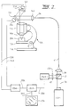
- FIG. 1 illustrates a scanning confocal epi-illumination microscope system in accordance with the invention.
- This system comprises a high intensity light source in the form of a laser generator 1 to supply a light beam 2 which is focused by a lens 3 into one end of a flexible optical fibre 4.
- the other end of optical fibre 4 runs into one side of a directional coupler 5 which may be a fused biconical taper coupler or other coupler for separating light rays travelling in opposite directions.
- the light going into one of the outgoing limbs 6 at the other side of the coupler is absorbed with minimum Fresnel reflection by an indexing matching media body 7 while light going into the other leg of the coupler at that side is transmitted by flexible optical fibre 8 from the end 9 of which it is transmitted to the optical train of an optical microscope denoted generally as 10.
- Optical microscope 10 comprises a base 11 on which there is mounted a mechanically adjustable specimen support platform 12 and a microscope body 13 housing the components defining the optical train of the microscope.
- These optical components comprise a lens 14 to receive the light 15 diverging from the end 9 of fibre 8, a pair of mirrors 16, 17 by which the light transmitted through lens 14 is successively reflected via a beam converging lens 19 to a light condenser in the form of a lens 18 which condenses or focuses the light onto a spot or point observational field in a specimen 20 supported on the platform 12.
- Mirrors 16, 17 can be moved by transducers 21, 22 in response to signals supplied through electrical connections 23, 24 from an electronic scanning signal generator 25 such that the reflected light beam is moved in X and Y directions to cause the illuminated spot to traverse the specimen in a scanning pattern.
- Scanning means of this kind is used in conventional scanning confocal microscopes.
- the condenser lens 18 also receives light emanating from the specimen which is transmitted back through the optical train of the microscope 10 to the optical fibre 8. Depending on the nature of the specimen, this light emanating from the specimen may comprise reflected light, Raman scattered light or fluorescent light. It is to be understood that the term "emanating" as used in this specification is to be construed in a broad sense as covering any light transmitted back from the object through the condenser.
- This light reconverges to a focus back at the tip 9 of optical fibre 8 and travels back up that fibre to the coupler 5 where a portion of that light is transmitted via the fourth leg of the coupler and a further flexible optical fibre 31 then via a filter 32 and lens 33 to a photo-detector 34.
- the signal from photo-detector 34 passes through an electrical connection 35 to the signal processor 36 of a video display system which produces an image on a display screen 37.
- the signal from photo-detector 34 modulates the intensity of the image signal transmitted from the processing circuit 36 through output line 38 to the display screen 37 and the mechanical scanning movements of the mirrors 16, 17 are synchronized with the electronic raster scanning movements of the display system through an interconnection 39 between the electronic scanning signal generator 25 and the signal processing means 36 of the video display unit 37.
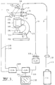
- FIG 2 illustrates a modified scanning confocal epi-illumination microscope system also constructed in accordance with the invention.
- This system is similar to that illustrated in Figure 1 but it employs a beam splitter as the means for separating the returning light from the outgoing light instead of the fused bi-conical taper coupler of the apparatus in Figure 1.
- Many of the components of the apparatus are identical to those of the system illustrated in Figure 1 and operate in the same manner. These components have been identified by the same reference numerals with the addition of the post script A.
- the fused bi-conical taper coupler and the associated multiple optical fibres are replaced by a single optical fibre 41 onto one end of which light from the laser 1A is focused by the lens 3A and from the other end of which the light diverges to the lens 14A of microscope head 10A to traverse the optical path in the head of the microscope and illuminate the specimen as described previously with reference to Figure 1.
- the returning light captured by the condenser 18A of the microscope head returns back through the same optical path and via fibre 41 to the lens 3A.
- This return light is separated by means of a beam splitter cube 42 interposed between the laser source 1A and the lens 3A and which diverts the returning light in a beam 43 detected by the photo-detector 34A.
- FIG 3 illustrates an alternative modified system in accordance with the invention in which the returning light is separated by means of a beam splitter disposed within the microscope head itself.
- components equivalent to those of the system illustrated in Figure 1 are identified by the same reference numerals but this time with the addition of the post script B.
- light from the laser source 1B is focused by the lens 3B onto one end of an optical fibre 51 which transmits the light to the microscope head 10B where it is transmitted through the optical train of the microscope head to focus on a spot on the specimen to be examined.
- Light emanating from the same spot on the specimen is captured by the condenser 18B of the microscope head and is transmitted back through the optical train of the microscope.
- the microscope head is modified by the addition of a beam splitter 52 which separates the returning light in the microscope head and focuses it through a lens 54 onto an end of a second optical fibre 53 via which it is transmitted to the photo-detector 34B of the system.
- a beam splitter 52 which separates the returning light in the microscope head and focuses it through a lens 54 onto an end of a second optical fibre 53 via which it is transmitted to the photo-detector 34B of the system.
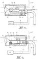
- FIGs 4, 5A and 5B illustrate a further modified scanning confocal microscope system constructed in accordance with the invention.
- This system is quite similar to that illustrated in Figure 1 and like components have been identified by the same reference numerals with the addition of the post script C.
- the modification which has been made to the apparatus as previously described with reference to Figure 1 is that scanning is now achieved by movement of the tip 9C of the optical fibre 8C through which light from the laser generator 1C is being transmitted to the microscope head 10C. Scanning movements of the fibre tip are generated by means of a movement generator 61.
- the movement generator may conveniently be an electro-mechanical transducer which received electrical signals from the scanning pattern generator 25C. This transducer may be of any convenient kind for generating appropriate scanning movements in the X and Y directions.
- Figures 5A and 5B which are side and top views of a typical device.
- the scanning movements of the fibre tip 9C are provided by a combination of electromagnetically induced resonant oscillation and hydraulic movement.
- a permanent magnet 62 attached to a flexible reed 63 is periodically attracted by the electromagnet 64 under the influence of electrical pulses generated by the scan control unit 25C and carried to the optic head by the leads 65.
- the optic fibre 8C projects along the flexible reed and is vibrated by it thus generating the scan inn one dimension (say the X direction). To ensure that the electronic image scanning is synchronized with the mechanical scanning, positional feedback is provided from a piezo electric sensor 66 feeding back via leads 67 to the image processing unit 36C.
- the other scan axis movement is generated by a slower quasi-linear movement produced by the influx or efflux of liquid from a supply tube 70 into a cylinder 68 thus actuating a piston 69 which carries the entire electromagnetic scanning unit so that the fibre tip is thus moved in the Y direction.
- the light source, detector and display system may be located at any position remotely from the other components, such as the opto-mechanical components usually incorporated in an optical microscope.
- These systems therefore enable the production of laser imaging equipment which can be attached to existing conventional microscopes so as to use the standard microscope optics and mechanical adjustments.
- the possibility of separating the optical head from the remainder of the system making use of optical fibre connections also opens the possibility for miniaturisation of the optical head, particularly if scanning is achieved by fibre movements. It is thus possible to apply the invention to endoscopy and other fields where a compact and remote head is required.
- FIG 6 illustrates a modified system constructed in accordance with the invention in which components corresponding to those of the system illustrated in Figure 1 are identified by the same reference numerals with addition of the post script F.
- the microscope head 10 is replaced by a compact optic head 10F for the examination of teeth, particularly for the detection of early caries pockets in the dentine below the enamel.
- the optic head 10F comprises a rigid housing 101 which receives the end of optical fibre 8F, the tip 9F of which is moved by an electro-mechanical transducer 102 to produce the required scan.
- Housing 101 contains the condenser lens 103 of the system and a lens 110 and mirror 105 to provide the optic path between the fibre 8E and the condenser lens 103.
- a "sandwich" layer 104 of spongy or soft flexible material is adhered to the side of housing 101 opposite to the condenser lens 103 and this is covered by a relatively hard plate 106.
- Optic head 10F is gripped between a tooth 107 to be examined and an opposite tooth 108 so that the tooth to be examined is disposed over the condenser lens 103 and the opposite tooth grips the plate 106.
- Sandwich layer 104 allows some relative movement between the teeth without causing movement between the optical head and the tooth being scanned.
- a tube 109 may be provided to introduce index matching gel or viscous fluid into the space between the objective lens and the tooth being examined.
- Figure 7 illustrates a further confocal microscope system constructed in accordance with the invention.
- This system uses a concave spherical mirror as the light condenser rather than a lens system.
- Components of the system corresponding to those of Figure 1 have been identified by the same reference numerals with the post script G.
- the tip 9G of the optical fibre 8G is located close to a table 111 to support a specimen 112 to be examined.
- the fibre tip and the table are disposed close to and on opposite sides of the centre of curvature of a concave spherical mirror 113.
- the light emitted from the fibre tip is returned by the mirror to a focus on the specimen.
- Light emanating from the specimen due to reflection or fluorescence then returns confocally back to the fibre tip and hence to the photo-detector 34G.
- An electro-magnetic transducer 114 is attached to the fibre tip and receives signals from the scanning signal generator 25G to cause scanning movements of the fibre tip. It will be appreciated that scanning might alternatively be achieved by movement of the specimen support table 115 or by a combination of movements of both the specimen support table and the fibre tip.
- Figure 8 illustrates a confocal system which enables use of the microscope heads in alternation.
- the system is a modification of the system illustrated in Figure 1 and the components equivalent to those in the system of Figure 1 are designated by the same reference numerals with the addition of the post script H.
- the limb 6H of the coupler 5H is not blanked off by connection to an absorber body but is connected by a fibre 121 to a second microscope head 10H' which may be identical to the first microscope head 10H and also has its scanning mirror transducers 23H' and 24H' connected to the scanning signal generator 25H.
- one microscope head can be set up and focused onto a specimen while the other is being used for confocal viewing and can then be brought in the operation for confocal viewing as soon as viewing with the other head has been completed. In this way the system can be maintained in virtually continuous operation.
- the illustrated embodiments of the invention have been advanced by way of example only and they could be modified and developed further to take advantage of optical fibre technology.
- single optical fibres are used for transmission of the light beam
- multiple fibres may be used.
- the tips of the fibres which receive the returning object emanated light to produce a confocal image may be staggered slightly longitudinally of the fibre (i.e. in the direction of light travel) to enable the depth of the viewing field to be increased.
- scanning is achieved by fibre movement the whole bundle of fibres may be attached to the transducer or other fibre movement generator so as to be moved together.
- the staggered fibre tips may be fixed in place relative to the light condenser.
- Use of multiple fibres will also enable simultaneous scanning at differing wavelengths.
- optical coupler in Figure 1 could be transversely cleaved at its midpoint so as to produce an end or tip from which light is transmitted to the microscope head and on which object emanated light is focused to produce the confocal image.
- Fibre 8 would then be eliminated and the end of the cleaved coupler would take the place of the fibre end or tip 9.
- the cleaved coupler could have three convergent limbs with the additional limb supplying light from a laser source of a different wavelength to enable multiple wavelength scanning.
- the invention has particular application to scanning confocal microscopes for laboratory use and to confocal microscope systems which have compact remote heads suitable for use in endoscopic or other examination of living biological tissue.
Landscapes
- Physics & Mathematics (AREA)
- Optics & Photonics (AREA)
- Chemical & Material Sciences (AREA)
- Analytical Chemistry (AREA)
- General Physics & Mathematics (AREA)
- Health & Medical Sciences (AREA)
- Spectroscopy & Molecular Physics (AREA)
- General Health & Medical Sciences (AREA)
- Ophthalmology & Optometry (AREA)
- Radiology & Medical Imaging (AREA)
- Surgery (AREA)
- Microscoopes, Condenser (AREA)
- Endoscopes (AREA)
- Length Measuring Devices By Optical Means (AREA)
Priority Applications (1)
| Application Number | Priority Date | Filing Date | Title |
|---|---|---|---|
| EP02012428A EP1245987B1 (fr) | 1988-07-13 | 1989-07-13 | Microscope confocal à balayage |
Applications Claiming Priority (7)
| Application Number | Priority Date | Filing Date | Title |
|---|---|---|---|
| AUPI9270/88 | 1988-07-13 | ||
| AUPI927088 | 1988-07-13 | ||
| AUPI927088 | 1988-07-13 | ||
| AUPI961888 | 1988-08-02 | ||
| AUPI9618/88 | 1988-08-02 | ||
| AUPI961888 | 1988-08-02 | ||
| EP89908146A EP0393165B2 (fr) | 1988-07-13 | 1989-07-13 | Endoscope a balayage a foyer commun |
Related Parent Applications (2)
| Application Number | Title | Priority Date | Filing Date |
|---|---|---|---|
| EP89908146A Division EP0393165B2 (fr) | 1988-07-13 | 1989-07-13 | Endoscope a balayage a foyer commun |
| EP89908146.7 Division | 1990-01-30 |
Related Child Applications (1)
| Application Number | Title | Priority Date | Filing Date |
|---|---|---|---|
| EP02012428A Division EP1245987B1 (fr) | 1988-07-13 | 1989-07-13 | Microscope confocal à balayage |
Publications (3)
| Publication Number | Publication Date |
|---|---|
| EP0782027A2 true EP0782027A2 (fr) | 1997-07-02 |
| EP0782027A3 EP0782027A3 (fr) | 1997-07-30 |
| EP0782027B1 EP0782027B1 (fr) | 2003-04-16 |
Family
ID=25643506
Family Applications (3)
| Application Number | Title | Priority Date | Filing Date |
|---|---|---|---|
| EP02012428A Expired - Lifetime EP1245987B1 (fr) | 1988-07-13 | 1989-07-13 | Microscope confocal à balayage |
| EP97200380A Expired - Lifetime EP0782027B1 (fr) | 1988-07-13 | 1989-07-13 | Microscope à balayage |
| EP89908146A Expired - Lifetime EP0393165B2 (fr) | 1988-07-13 | 1989-07-13 | Endoscope a balayage a foyer commun |
Family Applications Before (1)
| Application Number | Title | Priority Date | Filing Date |
|---|---|---|---|
| EP02012428A Expired - Lifetime EP1245987B1 (fr) | 1988-07-13 | 1989-07-13 | Microscope confocal à balayage |
Family Applications After (1)
| Application Number | Title | Priority Date | Filing Date |
|---|---|---|---|
| EP89908146A Expired - Lifetime EP0393165B2 (fr) | 1988-07-13 | 1989-07-13 | Endoscope a balayage a foyer commun |
Country Status (5)
| Country | Link |
|---|---|
| US (1) | US5120953A (fr) |
| EP (3) | EP1245987B1 (fr) |
| AT (1) | ATE158659T1 (fr) |
| DE (4) | DE68929553T2 (fr) |
| WO (1) | WO1990000754A1 (fr) |
Cited By (6)
| Publication number | Priority date | Publication date | Assignee | Title |
|---|---|---|---|---|
| WO2001022146A1 (fr) * | 1999-09-22 | 2001-03-29 | B.J.R. Systems Ltd. | Appareil d'imagerie confocal destine a produire des images d'un objet situe dans un milieu trouble |
| EP0977069A3 (fr) * | 1998-07-04 | 2001-10-04 | CARL ZEISS JENA GmbH | Dispositif et méthode pour la microscopie confocale |
| GB2363025A (en) * | 2000-04-04 | 2001-12-05 | Optiscan Pty Ltd | Z sharpening for fibre confocal microscopes |
| WO2002088819A3 (fr) * | 2001-04-28 | 2003-09-25 | Evotec Ag | Dispositif et procede de mesure optique d'echantillons chimiques et/ou biologiques |
| EP1240535A4 (fr) * | 1999-11-16 | 2005-07-20 | Ikonisys Inc | Microscope de composition |
| US8324562B2 (en) | 2007-07-20 | 2012-12-04 | Koninklijke Philips Electronics N.V. | Fiber scanning system having a magnet attached to the fiber at a position before or after an electrical coil with improved tip positioning |
Families Citing this family (220)
| Publication number | Priority date | Publication date | Assignee | Title |
|---|---|---|---|---|
| CA1325537C (fr) * | 1988-08-01 | 1993-12-28 | Timothy Peter Dabbs | Microscope a focalisateurs a foyers coincidents |
| EP0666487A2 (fr) * | 1989-09-22 | 1995-08-09 | Fuji Photo Film Co., Ltd. | Microscope à balayage et mécanisme de balayage pour ce microscope |
| CA2079882C (fr) * | 1990-04-06 | 2001-07-31 | Martin Russell Harris | Microscope a miroirs a foyers confondus |
| EP0458601B1 (fr) * | 1990-05-22 | 1996-08-28 | Research Development Corporation Of Japan | Méthode et appareil pour mesurer l'absorption spectrale dans des échantillons opaques et méthode et appareil pour mesurer une distribution d'absorption microscopique |
| US5127730A (en) * | 1990-08-10 | 1992-07-07 | Regents Of The University Of Minnesota | Multi-color laser scanning confocal imaging system |
| WO1992006398A1 (fr) * | 1990-10-02 | 1992-04-16 | Patrick Foulgoc | Dispositif de prise de vue et de projection |
| US5321501A (en) | 1991-04-29 | 1994-06-14 | Massachusetts Institute Of Technology | Method and apparatus for optical imaging with means for controlling the longitudinal range of the sample |
| DE9110926U1 (de) * | 1991-09-03 | 1991-12-19 | Max-Planck-Gesellschaft zur Förderung der Wissenschaften eV, 37073 Göttingen | Blitzlicht-Beleuchtungseinrichtung für ein Mikroskop |
| JP3082346B2 (ja) * | 1991-09-12 | 2000-08-28 | 株式会社ニコン | 蛍光コンフォーカル顕微鏡 |
| US5347656A (en) * | 1992-07-10 | 1994-09-20 | Ccc Acquisitions Corp. | Figure-enhancing pneumatic bathing suit |
| US5659642A (en) * | 1992-10-23 | 1997-08-19 | Optiscan Pty. Ltd. | Confocal microscope and endoscope |
| AU669760B2 (en) * | 1992-10-23 | 1996-06-20 | Monash University | Confocal microscope and endoscope |
| US5450203A (en) * | 1993-12-22 | 1995-09-12 | Electroglas, Inc. | Method and apparatus for determining an objects position, topography and for imaging |
| US20050111089A1 (en) * | 1994-07-15 | 2005-05-26 | Baer Stephen C. | Superresolving microscopy apparatus |
| US5880880A (en) * | 1995-01-13 | 1999-03-09 | The General Hospital Corp. | Three-dimensional scanning confocal laser microscope |
| WO1996021938A1 (fr) * | 1995-01-13 | 1996-07-18 | The General Hospital Corporation | Microscope a laser de balayage a foyer commun a vitesse video |
| US5926592A (en) * | 1995-03-24 | 1999-07-20 | Optiscan Pty Ltd | Optical fibre confocal imager with variable near-confocal control |
| US6175754B1 (en) | 1995-06-07 | 2001-01-16 | Keravision, Inc. | Method and apparatus for measuring corneal incisions |
| US5785651A (en) * | 1995-06-07 | 1998-07-28 | Keravision, Inc. | Distance measuring confocal microscope |
| US5788639A (en) * | 1995-07-13 | 1998-08-04 | Lucid Technologies, Inc. | Confocal imaging through thick dermal tissue |
| US7047064B1 (en) * | 1995-07-13 | 2006-05-16 | Lucid, Inc. | Microscopic imaging apparatus and method |
| US6263233B1 (en) | 1995-07-13 | 2001-07-17 | Lucid, Inc. | Handheld imaging microscope |
| US5813987A (en) * | 1995-08-01 | 1998-09-29 | Medispectra, Inc. | Spectral volume microprobe for analysis of materials |
| US6104945A (en) * | 1995-08-01 | 2000-08-15 | Medispectra, Inc. | Spectral volume microprobe arrays |
| US5713364A (en) * | 1995-08-01 | 1998-02-03 | Medispectra, Inc. | Spectral volume microprobe analysis of materials |
| US5874726A (en) * | 1995-10-10 | 1999-02-23 | Iowa State University Research Foundation | Probe-type near-field confocal having feedback for adjusting probe distance |
| US5907425A (en) * | 1995-12-19 | 1999-05-25 | The Board Of Trustees Of The Leland Stanford Junior University | Miniature scanning confocal microscope |
| US6749346B1 (en) | 1995-11-07 | 2004-06-15 | The Board Of Trustees Of The Leland Stanford Junior University | Miniature scanning confocal microscope |
| US6081499A (en) * | 1997-05-05 | 2000-06-27 | Seagate Technology, Inc. | Magneto-optical data storage system having an optical-processing flying head |
| DE19640496A1 (de) * | 1996-10-01 | 1998-04-02 | Leica Lasertechnik | Verfahren zur Oberflächenvermessung mittels Konfokalmikroskopie |
| US6745067B1 (en) * | 1998-09-14 | 2004-06-01 | Lucid, Inc. | System for marking the locations of imaged tissue with respect to the surface of the tissue |
| US6424852B1 (en) | 1996-10-18 | 2002-07-23 | Lucid, Inc. | System for confocal imaging within dermal tissue |
| US6826422B1 (en) | 1997-01-13 | 2004-11-30 | Medispectra, Inc. | Spectral volume microprobe arrays |
| US6847490B1 (en) | 1997-01-13 | 2005-01-25 | Medispectra, Inc. | Optical probe accessory device for use in vivo diagnostic procedures |
| DE19758744C2 (de) * | 1997-01-27 | 2003-08-07 | Zeiss Carl Jena Gmbh | Laser-Scanning-Mikroskop |
| US5887009A (en) * | 1997-05-22 | 1999-03-23 | Optical Biopsy Technologies, Inc. | Confocal optical scanning system employing a fiber laser |
| US5876946A (en) * | 1997-06-03 | 1999-03-02 | Pharmacopeia, Inc. | High-throughput assay |
| EP1925961B1 (fr) | 1997-06-30 | 2017-03-29 | Lucid, Inc. | Imagerie confocale par des tissus dermiques épais |
| US6967772B2 (en) * | 1997-07-16 | 2005-11-22 | Optiscan Pty Ltd | Scanning microscope with miniature head |
| US6069698A (en) * | 1997-08-28 | 2000-05-30 | Olympus Optical Co., Ltd. | Optical imaging apparatus which radiates a low coherence light beam onto a test object, receives optical information from light scattered by the object, and constructs therefrom a cross-sectional image of the object |
| US6327493B1 (en) | 1997-08-28 | 2001-12-04 | Olympus Optical Co., Ltd. | Light scanning devices of a water-tight structure to be inserted into a body cavity to obtain optical information on inside of a biological tissue |
| US6121603A (en) * | 1997-12-01 | 2000-09-19 | Hang; Zhijiang | Optical confocal device having a common light directing means |
| WO1999043994A1 (fr) | 1998-02-26 | 1999-09-02 | Lucid, Inc. | Microscope confocal destine a faciliter la cryochirurgie de tissus |
| WO1999047041A1 (fr) * | 1998-03-19 | 1999-09-23 | Board Of Regents, The University Of Texas System | Appareil d'imagerie confocal a fibres optiques et ses procedes d'utilisation |
| US6587421B1 (en) | 1998-03-30 | 2003-07-01 | Seagate Technology Llc | Refractive index matching means coupled to an optical fiber for eliminating spurious light |
| US6298027B1 (en) | 1998-03-30 | 2001-10-02 | Seagate Technology Llc | Low-birefringence optical fiber for use in an optical data storage system |
| US6574015B1 (en) | 1998-05-19 | 2003-06-03 | Seagate Technology Llc | Optical depolarizer |
| AUPP548298A0 (en) * | 1998-08-27 | 1998-09-17 | Optiscan Pty Limited | Compact confocal endoscope and endomicroscope method and apparatus |
| FR2783330B1 (fr) * | 1998-09-15 | 2002-06-14 | Assist Publ Hopitaux De Paris | Dispositif d'observation de l'interieur d'un corps produisant une qualite d'observation perfectionnee |
| DE59914599D1 (de) * | 1998-11-16 | 2008-02-14 | Leica Microsystems | Verfahren zum betrieb eines konfokalen laser scanning mikroskops |
| WO2000036973A1 (fr) | 1998-12-23 | 2000-06-29 | Medispectra, Inc. | Systemes et techniques optiques destines a l'examen du col |
| JP2002533142A (ja) | 1998-12-23 | 2002-10-08 | メディスペクトラ, インコーポレイテッド | サンプルの光学的試験のためのシステムおよび方法 |
| ES2520140T3 (es) * | 1999-02-17 | 2014-11-11 | Lucid, Inc. | Portador de muestras de tejido |
| WO2000049392A1 (fr) * | 1999-02-17 | 2000-08-24 | Lucid, Inc. | Cassette destinee a faciliter le sectionnement optique d'un prelevement de tissu retenu |
| JP2000258699A (ja) | 1999-03-05 | 2000-09-22 | Olympus Optical Co Ltd | 直視型共焦点光学系 |
| US6181474B1 (en) | 1999-03-22 | 2001-01-30 | Kovex Corporation | Scanning confocal microscope with objective lens position tracking |
| US6548796B1 (en) * | 1999-06-23 | 2003-04-15 | Regents Of The University Of Minnesota | Confocal macroscope |
| JP2001174744A (ja) | 1999-10-06 | 2001-06-29 | Olympus Optical Co Ltd | 光走査プローブ装置 |
| US6545260B1 (en) | 1999-11-19 | 2003-04-08 | Olympus Optical Co., Ltd. | Light scanning optical device which acquires a high resolution two-dimensional image without employing a charge-coupled device |
| US7260248B2 (en) | 1999-12-15 | 2007-08-21 | Medispectra, Inc. | Image processing using measures of similarity |
| US20020007122A1 (en) * | 1999-12-15 | 2002-01-17 | Howard Kaufman | Methods of diagnosing disease |
| US7187810B2 (en) | 1999-12-15 | 2007-03-06 | Medispectra, Inc. | Methods and systems for correcting image misalignment |
| JP2001311880A (ja) | 2000-04-28 | 2001-11-09 | Olympus Optical Co Ltd | 小型共焦点光学系 |
| US6747795B2 (en) * | 2000-06-30 | 2004-06-08 | The General Hospital Corporation | Fiber-coupled multiplexed confocal microscope |
| US6530882B1 (en) * | 2000-06-30 | 2003-03-11 | Inner Vision Imaging, L.L.C. | Endoscope having microscopic and macroscopic magnification |
| JP4668392B2 (ja) | 2000-07-26 | 2011-04-13 | オリンパス株式会社 | 光走査光学系および内視鏡 |
| US6423956B1 (en) * | 2000-07-28 | 2002-07-23 | Optical Biopsy Technologies | Fiber-coupled, high-speed, integrated, angled-dual-axis confocal scanning microscopes employing vertical cross-section scanning |
| US6351325B1 (en) | 2000-07-28 | 2002-02-26 | Optical Biopsy Technologies, Inc. | Fiber-coupled, angled-dual-axis confocal scanning microscopes for imaging in a scattering medium |
| US6441356B1 (en) | 2000-07-28 | 2002-08-27 | Optical Biopsy Technologies | Fiber-coupled, high-speed, angled-dual-axis optical coherence scanning microscopes |
| US7560697B2 (en) * | 2000-08-29 | 2009-07-14 | Perkinelmer Singapore Pte. Ltd. | Detector array and cross-talk linearity connection |
| ATE472119T1 (de) * | 2000-08-29 | 2010-07-15 | Perkinelmer Singapore Pte Ltd | Mikroskop für infrarotabbildung |
| ATE454845T1 (de) | 2000-10-30 | 2010-01-15 | Gen Hospital Corp | Optische systeme zur gewebeanalyse |
| US6369928B1 (en) | 2000-11-01 | 2002-04-09 | Optical Biopsy Technologies, Inc. | Fiber-coupled, angled-dual-illumination-axis confocal scanning microscopes for performing reflective and two-photon fluorescence imaging |
| US7194118B1 (en) | 2000-11-10 | 2007-03-20 | Lucid, Inc. | System for optically sectioning and mapping surgically excised tissue |
| US9295391B1 (en) | 2000-11-10 | 2016-03-29 | The General Hospital Corporation | Spectrally encoded miniature endoscopic imaging probe |
| EP1343973B2 (fr) | 2000-11-16 | 2020-09-16 | California Institute Of Technology | Appareil et procedes pour effectuer des dosages et des criblages a haut rendement |
| US6414779B1 (en) | 2000-11-30 | 2002-07-02 | Opeical Biopsy Technologies, Inc. | Integrated angled-dual-axis confocal scanning endoscopes |
| US6839661B2 (en) | 2000-12-15 | 2005-01-04 | Medispectra, Inc. | System for normalizing spectra |
| US7120501B2 (en) * | 2001-01-23 | 2006-10-10 | Microphonics, Inc. | Transcanal cochlear implant system |
| WO2002088684A1 (fr) * | 2001-04-30 | 2002-11-07 | The General Hospital Corporation | Procede et appareil permettant d'ameliorer la clarte et la sensibilite de l'image en tomographie a coherence optique au moyen d'une interaction permettant de controler les proprietes focales et la synchronisation de coherence |
| WO2002088705A2 (fr) | 2001-05-01 | 2002-11-07 | The General Hospital Corporation | Procede et appareil pour determiner un type de plaque d'atherosclerose par mesure de proprietes optiques de tissu |
| US7616986B2 (en) * | 2001-05-07 | 2009-11-10 | University Of Washington | Optical fiber scanner for performing multimodal optical imaging |
| DE10125885B4 (de) | 2001-05-28 | 2004-09-16 | Siemens Ag | Sensorvorrichtung zur schnellen optischen Abstandsmessung nach dem konfokalen optischen Abbildungsprinzip |
| US6809866B2 (en) * | 2001-08-03 | 2004-10-26 | Olympus Corporation | Optical imaging apparatus |
| US6980299B1 (en) | 2001-10-16 | 2005-12-27 | General Hospital Corporation | Systems and methods for imaging a sample |
| JP3678192B2 (ja) * | 2001-11-21 | 2005-08-03 | 横河電機株式会社 | 計測装置 |
| US8423110B2 (en) * | 2002-01-09 | 2013-04-16 | Boston Scientific Scimed, Inc. | Imaging device and related methods |
| AU2003207507A1 (en) * | 2002-01-11 | 2003-07-30 | Gen Hospital Corp | Apparatus for oct imaging with axial line focus for improved resolution and depth of field |
| US7355716B2 (en) | 2002-01-24 | 2008-04-08 | The General Hospital Corporation | Apparatus and method for ranging and noise reduction of low coherence interferometry LCI and optical coherence tomography OCT signals by parallel detection of spectral bands |
| US8229548B2 (en) * | 2002-03-12 | 2012-07-24 | Beth Israel Deaconess Medical Center | Medical imaging systems |
| US8620410B2 (en) * | 2002-03-12 | 2013-12-31 | Beth Israel Deaconess Medical Center | Multi-channel medical imaging system |
| US7309867B2 (en) | 2003-04-18 | 2007-12-18 | Medispectra, Inc. | Methods and apparatus for characterization of tissue samples |
| US6818903B2 (en) * | 2002-07-09 | 2004-11-16 | Medispectra, Inc. | Method and apparatus for identifying spectral artifacts |
| US7459696B2 (en) | 2003-04-18 | 2008-12-02 | Schomacker Kevin T | Methods and apparatus for calibrating spectral data |
| US7136518B2 (en) | 2003-04-18 | 2006-11-14 | Medispectra, Inc. | Methods and apparatus for displaying diagnostic data |
| US6933154B2 (en) * | 2002-07-09 | 2005-08-23 | Medispectra, Inc. | Optimal windows for obtaining optical data for characterization of tissue samples |
| US7282723B2 (en) | 2002-07-09 | 2007-10-16 | Medispectra, Inc. | Methods and apparatus for processing spectral data for use in tissue characterization |
| US7469160B2 (en) | 2003-04-18 | 2008-12-23 | Banks Perry S | Methods and apparatus for evaluating image focus |
| US20040208385A1 (en) * | 2003-04-18 | 2004-10-21 | Medispectra, Inc. | Methods and apparatus for visually enhancing images |
| US7103401B2 (en) | 2002-07-10 | 2006-09-05 | Medispectra, Inc. | Colonic polyp discrimination by tissue fluorescence and fiberoptic probe |
| US6768918B2 (en) | 2002-07-10 | 2004-07-27 | Medispectra, Inc. | Fluorescent fiberoptic probe for tissue health discrimination and method of use thereof |
| US7252634B2 (en) * | 2002-11-05 | 2007-08-07 | Pentax Corporation | Confocal probe having scanning mirrors mounted to a transparent substrate in an optical path of the probe |
| JP2004222870A (ja) * | 2003-01-21 | 2004-08-12 | Pentax Corp | 内視鏡用プローブ |
| US7761139B2 (en) * | 2003-01-24 | 2010-07-20 | The General Hospital Corporation | System and method for identifying tissue using low-coherence interferometry |
| US7643153B2 (en) | 2003-01-24 | 2010-01-05 | The General Hospital Corporation | Apparatus and method for ranging and noise reduction of low coherence interferometry LCI and optical coherence tomography OCT signals by parallel detection of spectral bands |
| DE102004006541B4 (de) | 2003-02-10 | 2016-11-10 | Hoya Corp. | Endoskop |
| JP4320184B2 (ja) * | 2003-02-10 | 2009-08-26 | Hoya株式会社 | 対物レンズユニット、該対物レンズユニットの組立方法 |
| US7154083B2 (en) * | 2003-02-24 | 2006-12-26 | Pentax Corporation | Confocal probe |
| CA2519937C (fr) | 2003-03-31 | 2012-11-20 | Guillermo J. Tearney | Reduction de granularite dans la tomographie par coherence optique au moyen d'une composition angulaire par codage de longueur de trajet |
| US7401984B2 (en) * | 2003-05-16 | 2008-07-22 | Hoya Corporation | Optical connector |
| ES2310744T3 (es) | 2003-06-06 | 2009-01-16 | The General Hospital Corporation | Fuente de luz sintonizable en longitudes de onda. |
| KR100556232B1 (ko) * | 2003-07-23 | 2006-03-03 | 국립암센터 | 이격조절이 가능한 양안구조 복강경 |
| DE10335466B4 (de) | 2003-08-02 | 2005-09-01 | Leica Microsystems Heidelberg Gmbh | Rastermikroskop |
| AU2003272531A1 (en) * | 2003-09-15 | 2005-04-27 | Beth Israel Deaconess Medical Center | Medical imaging systems |
| DE602004014697D1 (de) * | 2003-10-17 | 2008-08-14 | Olympus Co | Objektiveinführvorrichtung, Befestigungsvorrichtung für ein Objektivsystem |
| EP2278287B1 (fr) | 2003-10-27 | 2016-09-07 | The General Hospital Corporation | Procédé et appareil de l'imagerie optique avec de l'interférométrie dans le domaine de fréquence |
| EP1687587B1 (fr) * | 2003-11-28 | 2020-01-08 | The General Hospital Corporation | Procede et appareil d'imagerie codee de maniere spectrale tridimensionnelle |
| JP2005189475A (ja) * | 2003-12-25 | 2005-07-14 | Fujinon Corp | 顕微鏡装置 |
| EP1566617B1 (fr) * | 2004-02-20 | 2015-11-11 | Carestream Health, Inc. | Equipement et procédé de mesure de teinte dentaire |
| US7233437B2 (en) | 2004-03-25 | 2007-06-19 | Olympus Corporation | Laser-scanning microscope |
| JP4694139B2 (ja) * | 2004-04-01 | 2011-06-08 | オリンパス株式会社 | 顕微鏡 |
| US8018598B2 (en) | 2004-05-29 | 2011-09-13 | The General Hospital Corporation | Process, system and software arrangement for a chromatic dispersion compensation using reflective layers in optical coherence tomography (OCT) imaging |
| AU2005270037B2 (en) | 2004-07-02 | 2012-02-09 | The General Hospital Corporation | Endoscopic imaging probe comprising dual clad fibre |
| JP5053845B2 (ja) | 2004-08-06 | 2012-10-24 | ザ ジェネラル ホスピタル コーポレイション | 光学コヒーレンス断層撮影法を使用して試料中の少なくとも1つの位置を決定するための方法、システムおよびソフトウェア装置 |
| JP5324095B2 (ja) | 2004-08-24 | 2013-10-23 | ザ ジェネラル ホスピタル コーポレイション | 血管セグメントを画像化する方法および装置 |
| EP1989997A1 (fr) | 2004-08-24 | 2008-11-12 | The General Hospital Corporation | Procèdé, Système et logiciel pour la mesure de la contrainte mécanique et des propriétés élastiques d'un echantillon |
| US7365859B2 (en) * | 2004-09-10 | 2008-04-29 | The General Hospital Corporation | System and method for optical coherence imaging |
| EP1804638B1 (fr) * | 2004-09-29 | 2012-12-19 | The General Hospital Corporation | Systeme et procede d'imagerie a coherence optique |
| EP1650529A1 (fr) * | 2004-10-19 | 2006-04-26 | Diener AG Precision Machining | Dispositif et procédé pour balayer plusieurs objets |
| EP1819270B1 (fr) * | 2004-10-29 | 2012-12-19 | The General Hospital Corporation | Systeme et procede d'analyse a base de matrice de jones pour determiner des parametres de polarisation/non polarisation en utilisant la tco sensible a la polarisation |
| EP1807722B1 (fr) * | 2004-11-02 | 2022-08-10 | The General Hospital Corporation | Dispositif rotationnel a fibres optiques, systeme optique pour imager un echantillon |
| EP2278266A3 (fr) | 2004-11-24 | 2011-06-29 | The General Hospital Corporation | Interféromètre à chemin commun pour OCT endoscopique |
| WO2006056014A1 (fr) * | 2004-11-25 | 2006-06-01 | Optiscan Pty Ltd | Endoscope |
| WO2006058346A1 (fr) | 2004-11-29 | 2006-06-01 | The General Hospital Corporation | Ensembles, dispositifs, endoscopes, catheters et methodes d'imagerie optique permettant d'eclairer et de detecter simultanement plusieurs points sur un echantillon |
| JP4759277B2 (ja) * | 2005-01-21 | 2011-08-31 | オリンパス株式会社 | 観察方法および観察補助具 |
| WO2006113482A1 (fr) * | 2005-04-14 | 2006-10-26 | The Government Of The United States Of America, As Represented By The Secretary Of Health And Human Services, National Institutes Of Health | Microscope confocal a fibre optique a resolution ultra-elevee et procede d'utilisation |
| EP2325803A1 (fr) | 2005-04-28 | 2011-05-25 | The General Hospital Corporation | Evaluation des informations de tomographie par cohérence optique pour une structure anatomique |
| US9055867B2 (en) | 2005-05-12 | 2015-06-16 | Caliber Imaging & Diagnostics, Inc. | Confocal scanning microscope having optical and scanning systems which provide a handheld imaging head |
| EP1887926B1 (fr) * | 2005-05-31 | 2014-07-30 | The General Hospital Corporation | Systeme et procede qui utilisent des techniques d'interferometrie d'heterodyne a codage spectral pour l'imagerie |
| EP1889037A2 (fr) | 2005-06-01 | 2008-02-20 | The General Hospital Corporation | Appareil, methode et systeme pour effectuer une imagerie de domaine de frequence optique a resolution de phase |
| DE602006017558D1 (de) | 2005-08-09 | 2010-11-25 | Gen Hospital Corp | Gerät und verfahren zur durchführung von polarisationsbasierter quadraturdemodulation bei optischer kohärenztomographie |
| GB0519761D0 (en) * | 2005-09-28 | 2005-11-09 | Point Source Ltd | Laser systems |
| EP1940286A1 (fr) | 2005-09-29 | 2008-07-09 | General Hospital Corporation | Procede et appareil destines a un procede pour visualiser et analyser un ou plusieurs echantillons biologiques avec des resolutions augmentant progressivement |
| JP5203951B2 (ja) | 2005-10-14 | 2013-06-05 | ザ ジェネラル ホスピタル コーポレイション | スペクトル及び周波数符号化蛍光画像形成 |
| CN101365397B (zh) * | 2005-12-08 | 2012-04-18 | 彼得·S·乐芙莉 | 红外牙齿成像 |
| US7796270B2 (en) | 2006-01-10 | 2010-09-14 | The General Hospital Corporation | Systems and methods for generating data based on one or more spectrally-encoded endoscopy techniques |
| WO2007084903A2 (fr) | 2006-01-19 | 2007-07-26 | The General Hospital Corporation | Dispositif de collecte d'information pour une structure utilisant des techniques d'endoscopie à codage spectral, et procédé d'élaboration correspondant |
| CN101384212A (zh) | 2006-01-19 | 2009-03-11 | 通用医疗公司 | 通过上皮内腔器官束扫描对上皮内腔器官进行光学成像的方法和系统 |
| WO2007084945A1 (fr) * | 2006-01-19 | 2007-07-26 | The General Hospital Corporation | Systemes et procedes pour realiser des mesures rapides de durees de vies de la fluorescence, de l'excitation et de l'emission spectrale |
| US20070171430A1 (en) * | 2006-01-20 | 2007-07-26 | The General Hospital Corporation | Systems and methods for providing mirror tunnel micropscopy |
| US9186066B2 (en) | 2006-02-01 | 2015-11-17 | The General Hospital Corporation | Apparatus for applying a plurality of electro-magnetic radiations to a sample |
| US10426548B2 (en) | 2006-02-01 | 2019-10-01 | The General Hosppital Corporation | Methods and systems for providing electromagnetic radiation to at least one portion of a sample using conformal laser therapy procedures |
| WO2007149601A2 (fr) * | 2006-02-01 | 2007-12-27 | The General Hospital Corporation | Appareil destiné à commander au moins l'une d'au moins deux sections d'au moins une fibre |
| EP3143926B1 (fr) | 2006-02-08 | 2020-07-01 | The General Hospital Corporation | Procédés, agencements et systèmes pour obtenir des informations associées à un prélèvement anatomique utilisant la microscopie optique |
| JP2009527770A (ja) | 2006-02-24 | 2009-07-30 | ザ ジェネラル ホスピタル コーポレイション | 角度分解型のフーリエドメイン光干渉断層撮影法を遂行する方法及びシステム |
| WO2007109540A2 (fr) * | 2006-03-17 | 2007-09-27 | The General Hospital Corporation | Appareil, procédé et support accessible par ordinateur pour l'identification de caractéristiques d'au moins une partie d'un vaisseau sanguin compris à l'intérieur d'un tissu au moyen d'une interférométrie faible cohérence à domaine spectral |
| US7742173B2 (en) * | 2006-04-05 | 2010-06-22 | The General Hospital Corporation | Methods, arrangements and systems for polarization-sensitive optical frequency domain imaging of a sample |
| EP3150110B1 (fr) | 2006-05-10 | 2020-09-02 | The General Hospital Corporation | Processus, agencements et systèmes pour fournir une imagerie de domaine de fréquence d'un échantillon |
| US7782464B2 (en) * | 2006-05-12 | 2010-08-24 | The General Hospital Corporation | Processes, arrangements and systems for providing a fiber layer thickness map based on optical coherence tomography images |
| EP2054712B1 (fr) | 2006-08-25 | 2015-10-07 | The General Hospital Corporation | Appareil et procédés permettant d'améliorer l'imagerie de tomographie par cohérence optique mettant en oeuvre des techniques de filtrage volumétrique |
| WO2008049118A2 (fr) | 2006-10-19 | 2008-04-24 | The General Hospital Corporation | Dispositif et procédé d'obtention et de fourniture d'informations d'image associées à au moins une portion d' échantillon et permettant de réaliser une telle portion |
| GB0621585D0 (en) * | 2006-10-30 | 2006-12-06 | Secretary Trade Ind Brit | Confocal microscope |
| WO2008089342A1 (fr) | 2007-01-19 | 2008-07-24 | The General Hospital Corporation | Réflexion de disque rotatif pour balayage de longueurs d'onde rapide de lumière à large bande dispersée |
| US20080206804A1 (en) * | 2007-01-19 | 2008-08-28 | The General Hospital Corporation | Arrangements and methods for multidimensional multiplexed luminescence imaging and diagnosis |
| WO2008089406A2 (fr) | 2007-01-19 | 2008-07-24 | The General Hospital Corporation | Appareil et procédé pour contrôler la profondeur de télémétrie dans une imagerie de domaine de fréquence optique |
| WO2008116010A1 (fr) * | 2007-03-19 | 2008-09-25 | The General Hospital Corporation | Système et procédé permettant un diagnostic non invasif du syndrome de compartiment, exemples de procédure d'imagerie de points par laser |
| EP2602651A3 (fr) | 2007-03-23 | 2014-08-27 | The General Hospital Corporation | Procédés, agencements et appareil pour utiliser un laser à balayage de longueur d'ondes utilisant un balayage angulaire et des procédures de dispersion |
| US10534129B2 (en) | 2007-03-30 | 2020-01-14 | The General Hospital Corporation | System and method providing intracoronary laser speckle imaging for the detection of vulnerable plaque |
| US8045177B2 (en) | 2007-04-17 | 2011-10-25 | The General Hospital Corporation | Apparatus and methods for measuring vibrations using spectrally-encoded endoscopy |
| US8115919B2 (en) | 2007-05-04 | 2012-02-14 | The General Hospital Corporation | Methods, arrangements and systems for obtaining information associated with a sample using optical microscopy |
| WO2009018456A2 (fr) | 2007-07-31 | 2009-02-05 | The General Hospital Corporation | Systèmes et procédés pour fournir des motifs de balayage de faisceau pour une imagerie dans le domaine de la fréquence optique doppler de vitesse élevée |
| EP2191254B1 (fr) | 2007-08-31 | 2017-07-19 | The General Hospital Corporation | Systeme et procede pour une microscopie par fluorescence a auto-interference, et support lisible par ordinateur associe à ceux-ci |
| JP2011500173A (ja) * | 2007-10-12 | 2011-01-06 | ザ ジェネラル ホスピタル コーポレイション | 管腔解剖構造の光学イメージングのためのシステムおよびプロセス |
| WO2009059034A1 (fr) | 2007-10-30 | 2009-05-07 | The General Hospital Corporation | Système et procédé permettant une détection de mode de gaine |
| US11123047B2 (en) | 2008-01-28 | 2021-09-21 | The General Hospital Corporation | Hybrid systems and methods for multi-modal acquisition of intravascular imaging data and counteracting the effects of signal absorption in blood |
| US9332942B2 (en) * | 2008-01-28 | 2016-05-10 | The General Hospital Corporation | Systems, processes and computer-accessible medium for providing hybrid flourescence and optical coherence tomography imaging |
| US8593619B2 (en) | 2008-05-07 | 2013-11-26 | The General Hospital Corporation | System, method and computer-accessible medium for tracking vessel motion during three-dimensional coronary artery microscopy |
| JP5795531B2 (ja) | 2008-06-20 | 2015-10-14 | ザ ジェネラル ホスピタル コーポレイション | フューズドファイバオプティックカプラ構造、及びその使用方法 |
| WO2010009136A2 (fr) | 2008-07-14 | 2010-01-21 | The General Hospital Corporation | Appareil et procédés d'endoscopie couleur |
| EP2359121A4 (fr) | 2008-12-10 | 2013-08-14 | Gen Hospital Corp | Systèmes, appareil et procédés d'extension de la plage de profondeur d'imagerie de tomographie par cohérence optique, par le biais du sous-échantillonnage optique |
| JP2012515930A (ja) | 2009-01-26 | 2012-07-12 | ザ ジェネラル ホスピタル コーポレーション | 広視野の超解像顕微鏡を提供するためのシステム、方法及びコンピューターがアクセス可能な媒体 |
| US9178330B2 (en) * | 2009-02-04 | 2015-11-03 | The General Hospital Corporation | Apparatus and method for utilization of a high-speed optical wavelength tuning source |
| US9351642B2 (en) | 2009-03-12 | 2016-05-31 | The General Hospital Corporation | Non-contact optical system, computer-accessible medium and method for measurement at least one mechanical property of tissue using coherent speckle technique(s) |
| BR112012001042A2 (pt) | 2009-07-14 | 2016-11-22 | Gen Hospital Corp | equipamento e método de medição do fluxo de fluído dentro de estrutura anatômica. |
| FR2950441B1 (fr) * | 2009-09-23 | 2012-05-18 | Sabban Youssef Cohen | Capteur optique dote de champ lateral pour la numerisation 3d |
| EP2542145B1 (fr) | 2010-03-05 | 2020-08-12 | The General Hospital Corporation | Systèmes qui procurent des images microscopiques d'au moins une structure anatomique à une résolution particulière |
| US9069130B2 (en) | 2010-05-03 | 2015-06-30 | The General Hospital Corporation | Apparatus, method and system for generating optical radiation from biological gain media |
| EP2575597B1 (fr) | 2010-05-25 | 2022-05-04 | The General Hospital Corporation | Appareil pour fournir une imagerie optique de structures et de compositions |
| US9795301B2 (en) | 2010-05-25 | 2017-10-24 | The General Hospital Corporation | Apparatus, systems, methods and computer-accessible medium for spectral analysis of optical coherence tomography images |
| WO2011153434A2 (fr) | 2010-06-03 | 2011-12-08 | The General Hospital Corporation | Appareil et procédé pour dispositifs de structures d'imagerie, dans ou sur un ou plusieurs organes luminaux |
| JP5883018B2 (ja) | 2010-10-27 | 2016-03-09 | ザ ジェネラル ホスピタル コーポレイション | 少なくとも1つの血管内部の血圧を測定するための装置、システム、および方法 |
| US8721077B2 (en) | 2011-04-29 | 2014-05-13 | The General Hospital Corporation | Systems, methods and computer-readable medium for determining depth-resolved physical and/or optical properties of scattering media by analyzing measured data over a range of depths |
| CN103547883B (zh) | 2011-05-20 | 2017-06-13 | 加泰罗尼亚理工大学 | 用于非接触测量表面的方法和设备 |
| WO2013013049A1 (fr) | 2011-07-19 | 2013-01-24 | The General Hospital Corporation | Systèmes, procédés, appareils et supports accessibles par ordinateur permettant de produire une compensation de dispersion en mode polarisation dans la tomographie à cohérence optique |
| EP2748587B1 (fr) | 2011-08-25 | 2021-01-13 | The General Hospital Corporation | Procédés et arrangements permettant de mettre en oeuvre des procédures de tomographie par cohérence micro-optique |
| US9341783B2 (en) | 2011-10-18 | 2016-05-17 | The General Hospital Corporation | Apparatus and methods for producing and/or providing recirculating optical delay(s) |
| DE102011116403B4 (de) * | 2011-10-19 | 2013-05-29 | Rodenstock Gmbh | Vorrichtung und Verfahren zur Messung von Oberflächen oder Grenzflächen |
| CN103930816A (zh) * | 2011-11-14 | 2014-07-16 | 皇家飞利浦有限公司 | 用于相关联的对象的扫描显微镜检查的光学显微镜检查探头 |
| JP5930364B2 (ja) * | 2011-11-28 | 2016-06-08 | 国立大学法人京都大学 | 生体試料固定器 |
| EP2817609B1 (fr) | 2012-02-26 | 2021-04-07 | Caliber Imaging & Diagnostics Inc. | Platine d'échantillon de tissu pour un microscope à sectionnement optique |
| US9629528B2 (en) | 2012-03-30 | 2017-04-25 | The General Hospital Corporation | Imaging system, method and distal attachment for multidirectional field of view endoscopy |
| EP2852315A4 (fr) | 2012-05-21 | 2016-06-08 | Gen Hospital Corp | Appareil, dispositif et procédé pour microscopie par capsule |
| JP6227652B2 (ja) | 2012-08-22 | 2017-11-08 | ザ ジェネラル ホスピタル コーポレイション | ソフトリソグラフィを用いてミニチュア内視鏡を製作するためのシステム、方法、およびコンピュータ・アクセス可能媒体 |
| US10893806B2 (en) | 2013-01-29 | 2021-01-19 | The General Hospital Corporation | Apparatus, systems and methods for providing information regarding the aortic valve |
| WO2014121082A1 (fr) | 2013-02-01 | 2014-08-07 | The General Hospital Corporation | Agencement d'objectif pour endomicroscopie confocale |
| WO2014144709A2 (fr) | 2013-03-15 | 2014-09-18 | The General Hospital Corporation | Procédés et systèmes de caractérisation d'objet |
| EP2997354A4 (fr) | 2013-05-13 | 2017-01-18 | The General Hospital Corporation | Détection de la phase et de l'amplitude d'une fluorescence auto-interférente |
| US10045696B2 (en) * | 2013-07-19 | 2018-08-14 | Wisconsin Alumni Research Foundation | Tissue fluorescence monitor with ambient light rejection |
| WO2015009932A1 (fr) | 2013-07-19 | 2015-01-22 | The General Hospital Corporation | Appareil d'imagerie et procédé utilisant une endoscopie à champ de vision multidirectionnel |
| EP3021735A4 (fr) | 2013-07-19 | 2017-04-19 | The General Hospital Corporation | Détermination de mouvement oculaire au moyen d'une imagerie de la rétine avec rétroaction d'un mouvement de l'oeil par imagerie de la rétine et fournir des informations en retour pour l'acquisition de signaux venant de la rétine |
| WO2015013651A2 (fr) | 2013-07-26 | 2015-01-29 | The General Hospital Corporation | Système, appareil et procédé utilisant une dispersion optique pour réaliser une tomographie en cohérence optique dans le domaine de fourier |
| WO2015105870A1 (fr) | 2014-01-08 | 2015-07-16 | The General Hospital Corporation | Procédé et appareil pour imagerie microscopique |
| US10736494B2 (en) | 2014-01-31 | 2020-08-11 | The General Hospital Corporation | System and method for facilitating manual and/or automatic volumetric imaging with real-time tension or force feedback using a tethered imaging device |
| US10228556B2 (en) | 2014-04-04 | 2019-03-12 | The General Hospital Corporation | Apparatus and method for controlling propagation and/or transmission of electromagnetic radiation in flexible waveguide(s) |
| JP2017525435A (ja) | 2014-07-25 | 2017-09-07 | ザ ジェネラル ホスピタル コーポレイション | インビボ・イメージングおよび診断のための機器、デバイスならびに方法 |
| US20170307437A1 (en) * | 2014-10-01 | 2017-10-26 | Phonoptics | Opto-mechanical transducer for the detection of vibrations |
| FR3030956B1 (fr) * | 2014-12-18 | 2018-03-23 | Centre National De La Recherche Scientifique - Cnrs | Dispositif de transport et de controle d'impulsions lumineuses pour l'imagerie endo-microscopique sans lentille |
| DE102015202605B4 (de) * | 2015-02-12 | 2017-03-09 | Carl Zeiss Meditec Ag | Visualisierungssystem |
| US9645376B1 (en) | 2015-10-14 | 2017-05-09 | Abberior Instruments Gmbh | Scanner head and device with scanner head |
| CN111338069A (zh) * | 2020-04-13 | 2020-06-26 | 合肥登特菲医疗设备有限公司 | 一种口腔显微镜照明装置 |
Citations (7)
| Publication number | Priority date | Publication date | Assignee | Title |
|---|---|---|---|---|
| US4410235A (en) | 1979-09-10 | 1983-10-18 | Siemens Aktiengesellschaft | Device for producing a moving light beam |
| US4577177A (en) | 1983-06-01 | 1986-03-18 | Mitsubishi Denki Kabushiki Kaisha | Display apparatus for elevator car |
| GB2181539A (en) | 1985-10-08 | 1987-04-23 | Nat Res Dev | Fibre optic scanning system |
| US4713544A (en) | 1984-03-05 | 1987-12-15 | Siemens Aktiengesellschaft | Optical system for the simultaneous reception of thermal and laser radiation |
| US4768874A (en) | 1987-09-10 | 1988-09-06 | Eye Research Institute Of Retina Foundation | Scanning optical apparatus and method |
| US4770532A (en) | 1986-03-13 | 1988-09-13 | Hitachi, Ltd. | Equipment for optically measuring the height of step |
| WO1988008550A1 (fr) | 1987-04-29 | 1988-11-03 | Goldstein Seth R | Microscope a balayage laser a foyer commun, n'ayant aucune partie en mouvement |
Family Cites Families (17)
| Publication number | Priority date | Publication date | Assignee | Title |
|---|---|---|---|---|
| CH600301A5 (fr) * | 1976-05-28 | 1978-06-15 | Bbc Brown Boveri & Cie | |
| GB2038017B (en) * | 1978-12-20 | 1982-11-24 | Standard Telephones Cables Ltd | Optical fibre directional coupler |
| EP0058660A1 (fr) * | 1980-08-27 | 1982-09-01 | URBAN, Peter | Systeme endoscopique |
| US4500204A (en) * | 1981-04-21 | 1985-02-19 | Agency Of Industrial Science & Technology | Scanning-type lithographic and image-pickup device using optical fiber |
| US4634880A (en) * | 1982-04-19 | 1987-01-06 | Siscan Systems, Inc. | Confocal optical imaging system with improved signal-to-noise ratio |
| US4626679A (en) * | 1982-09-22 | 1986-12-02 | Canon Kabushiki Kaisha | Optical head and method of detecting the focus thereof |
| US4481418A (en) * | 1982-09-30 | 1984-11-06 | Vanzetti Systems, Inc. | Fiber optic scanning system for laser/thermal inspection |
| EP0112401B1 (fr) * | 1982-12-27 | 1987-04-22 | International Business Machines Corporation | Microscope de balayage optique de champ proche |
| US4589404A (en) * | 1984-01-03 | 1986-05-20 | Medical Dynamics, Inc. | Laser endoscope |
| US4754328A (en) * | 1984-01-03 | 1988-06-28 | Medical Dynamics, Inc. | Laser endoscope |
| DE3477271D1 (en) * | 1984-12-28 | 1989-04-20 | Ibm | Waveguide for an optical near-field microscope |
| FR2575889B1 (fr) † | 1985-01-09 | 1987-03-20 | Electricite De France | Microcamera de television |
| GB8617570D0 (en) * | 1986-07-18 | 1986-08-28 | See C W | Microscopes |
| EP0283256A3 (fr) * | 1987-03-18 | 1990-02-07 | Tektronix Inc. | Microscope à balayage optique |
| AU612201B2 (en) † | 1987-09-24 | 1991-07-04 | Washington University | Kit for converting a standard microscope into, and design for, a single aperture confocal scanning epi-illumination microscope |
| US4959552A (en) * | 1988-02-09 | 1990-09-25 | Carl-Zeiss-Stiftung | Microscope arranged for measuring microscopic structures |
| CA1325537C (fr) * | 1988-08-01 | 1993-12-28 | Timothy Peter Dabbs | Microscope a focalisateurs a foyers coincidents |
-
1989
- 1989-07-13 EP EP02012428A patent/EP1245987B1/fr not_active Expired - Lifetime
- 1989-07-13 EP EP97200380A patent/EP0782027B1/fr not_active Expired - Lifetime
- 1989-07-13 DE DE68929553T patent/DE68929553T2/de not_active Expired - Lifetime
- 1989-07-13 DE DE02012428T patent/DE02012428T1/de active Pending
- 1989-07-13 WO PCT/AU1989/000298 patent/WO1990000754A1/fr not_active Ceased
- 1989-07-13 AT AT89908146T patent/ATE158659T1/de not_active IP Right Cessation
- 1989-07-13 EP EP89908146A patent/EP0393165B2/fr not_active Expired - Lifetime
- 1989-07-13 DE DE68929464T patent/DE68929464T2/de not_active Expired - Lifetime
- 1989-07-13 DE DE68928345T patent/DE68928345T3/de not_active Expired - Lifetime
-
1990
- 1990-06-25 US US07/536,653 patent/US5120953A/en not_active Expired - Lifetime
Patent Citations (7)
| Publication number | Priority date | Publication date | Assignee | Title |
|---|---|---|---|---|
| US4410235A (en) | 1979-09-10 | 1983-10-18 | Siemens Aktiengesellschaft | Device for producing a moving light beam |
| US4577177A (en) | 1983-06-01 | 1986-03-18 | Mitsubishi Denki Kabushiki Kaisha | Display apparatus for elevator car |
| US4713544A (en) | 1984-03-05 | 1987-12-15 | Siemens Aktiengesellschaft | Optical system for the simultaneous reception of thermal and laser radiation |
| GB2181539A (en) | 1985-10-08 | 1987-04-23 | Nat Res Dev | Fibre optic scanning system |
| US4770532A (en) | 1986-03-13 | 1988-09-13 | Hitachi, Ltd. | Equipment for optically measuring the height of step |
| WO1988008550A1 (fr) | 1987-04-29 | 1988-11-03 | Goldstein Seth R | Microscope a balayage laser a foyer commun, n'ayant aucune partie en mouvement |
| US4768874A (en) | 1987-09-10 | 1988-09-06 | Eye Research Institute Of Retina Foundation | Scanning optical apparatus and method |
Non-Patent Citations (1)
| Title |
|---|
| M.BASS ET AL: "HANDBOOL OF OPTICS", vol. II, 1995, MCGRAW-HILL, INC., ISBN: 0-07-047974-7, XP000783738 |
Cited By (13)
| Publication number | Priority date | Publication date | Assignee | Title |
|---|---|---|---|---|
| EP0977069A3 (fr) * | 1998-07-04 | 2001-10-04 | CARL ZEISS JENA GmbH | Dispositif et méthode pour la microscopie confocale |
| USRE41666E1 (en) | 1998-07-04 | 2010-09-14 | Carl Zeiss Jena Gmbh | Process and arrangement for confocal microscopy |
| US6462345B1 (en) | 1998-07-04 | 2002-10-08 | Carl Zeiss Jena Gmbh | Process and arrangement for confocal microscopy |
| GB2372171B (en) * | 1999-09-22 | 2004-07-28 | B J R Systems Ltd | Confocal imaging apparatus for imaging an object situated within a turbid medium |
| WO2001022146A1 (fr) * | 1999-09-22 | 2001-03-29 | B.J.R. Systems Ltd. | Appareil d'imagerie confocal destine a produire des images d'un objet situe dans un milieu trouble |
| GB2372171A (en) * | 1999-09-22 | 2002-08-14 | B J R Systems Ltd | Confocal imaging apparatus for imaging an object situated within a turbid medium |
| EP1240535A4 (fr) * | 1999-11-16 | 2005-07-20 | Ikonisys Inc | Microscope de composition |
| GB2363025B (en) * | 2000-04-04 | 2002-08-07 | Optiscan Pty Ltd | Z sharpening for fibre confocal microscopes |
| US6567585B2 (en) | 2000-04-04 | 2003-05-20 | Optiscan Pty Ltd | Z sharpening for fibre confocal microscopes |
| GB2363025A (en) * | 2000-04-04 | 2001-12-05 | Optiscan Pty Ltd | Z sharpening for fibre confocal microscopes |
| WO2002088819A3 (fr) * | 2001-04-28 | 2003-09-25 | Evotec Ag | Dispositif et procede de mesure optique d'echantillons chimiques et/ou biologiques |
| US7474777B2 (en) | 2001-04-28 | 2009-01-06 | Evotec Oai Ag | Device and method for optical measurement of chemical and/or biological samples |
| US8324562B2 (en) | 2007-07-20 | 2012-12-04 | Koninklijke Philips Electronics N.V. | Fiber scanning system having a magnet attached to the fiber at a position before or after an electrical coil with improved tip positioning |
Also Published As
| Publication number | Publication date |
|---|---|
| DE68929464D1 (de) | 2003-05-22 |
| DE68928345T3 (de) | 2008-03-06 |
| EP1245987A3 (fr) | 2004-08-25 |
| DE02012428T1 (de) | 2005-12-15 |
| DE68928345T2 (de) | 1998-05-07 |
| EP0393165A4 (en) | 1991-07-24 |
| EP0393165A1 (fr) | 1990-10-24 |
| DE68929464T2 (de) | 2003-11-20 |
| EP0782027B1 (fr) | 2003-04-16 |
| ATE158659T1 (de) | 1997-10-15 |
| DE68929553D1 (de) | 2008-03-13 |
| EP0782027A3 (fr) | 1997-07-30 |
| EP0393165B1 (fr) | 1997-09-24 |
| EP0393165B2 (fr) | 2007-07-25 |
| EP1245987A2 (fr) | 2002-10-02 |
| WO1990000754A1 (fr) | 1990-01-25 |
| DE68928345D1 (de) | 1997-10-30 |
| EP1245987B1 (fr) | 2008-01-23 |
| US5120953A (en) | 1992-06-09 |
| DE68929553T2 (de) | 2009-01-29 |
Similar Documents
| Publication | Publication Date | Title |
|---|---|---|
| EP0782027B1 (fr) | Microscope à balayage | |
| US5323009A (en) | Conforcal microscope | |
| AU764675B2 (en) | Device for observation inside a body | |
| US5659642A (en) | Confocal microscope and endoscope | |
| JP4672260B2 (ja) | 画像装置 | |
| US9383568B2 (en) | Objective-coupled selective plane illumination microscopy | |
| JP2007501447A (ja) | ダブルクラッドファイバー走査型顕微鏡 | |
| JPH0387804A (ja) | スキャニング共焦点顕微鏡 | |
| JP2001327460A (ja) | 内視鏡装置 | |
| AU652713B2 (en) | Scanning confocal microscope | |
| CN106841141A (zh) | 一种基于光子重组的光纤环阵共振型压电扫描方法及装置 | |
| WO1994018592A1 (fr) | Microscope confocal | |
| AU643787B2 (en) | Confocal microscope | |
| AU672876B2 (en) | Confocal microscope | |
| JP2613130B2 (ja) | 共焦点走査型位相差顕微鏡 | |
| JPS62106365A (ja) | 顕微鏡装置 | |
| CN111208636A (zh) | 一种简易显微扫描仪 | |
| AU5330394A (en) | Confocal microscope and endoscope |
Legal Events
| Date | Code | Title | Description |
|---|---|---|---|
| PUAI | Public reference made under article 153(3) epc to a published international application that has entered the european phase |
Free format text: ORIGINAL CODE: 0009012 |
|
| PUAL | Search report despatched |
Free format text: ORIGINAL CODE: 0009013 |
|
| AC | Divisional application: reference to earlier application |
Ref document number: 393165 Country of ref document: EP |
|
| AK | Designated contracting states |
Kind code of ref document: A2 Designated state(s): DE FR GB IT |
|
| AK | Designated contracting states |
Kind code of ref document: A3 Designated state(s): DE FR GB IT |
|
| 17P | Request for examination filed |
Effective date: 19980116 |
|
| TPAD | Observations filed by third parties |
Free format text: ORIGINAL CODE: EPIDOS TIPA |
|
| 17Q | First examination report despatched |
Effective date: 19990520 |
|
| GRAH | Despatch of communication of intention to grant a patent |
Free format text: ORIGINAL CODE: EPIDOS IGRA |
|
| RTI1 | Title (correction) |
Free format text: SCANNING MICROSCOPE |
|
| GRAH | Despatch of communication of intention to grant a patent |
Free format text: ORIGINAL CODE: EPIDOS IGRA |
|
| GRAA | (expected) grant |
Free format text: ORIGINAL CODE: 0009210 |
|
| AC | Divisional application: reference to earlier application |
Ref document number: 0393165 Country of ref document: EP Kind code of ref document: P |
|
| AK | Designated contracting states |
Designated state(s): DE FR GB IT |
|
| REG | Reference to a national code |
Ref country code: GB Ref legal event code: FG4D |
|
| REF | Corresponds to: |
Ref document number: 68929464 Country of ref document: DE Date of ref document: 20030522 Kind code of ref document: P |
|
| ET | Fr: translation filed | ||
| PLBE | No opposition filed within time limit |
Free format text: ORIGINAL CODE: 0009261 |
|
| STAA | Information on the status of an ep patent application or granted ep patent |
Free format text: STATUS: NO OPPOSITION FILED WITHIN TIME LIMIT |
|
| 26N | No opposition filed |
Effective date: 20040119 |
|
| PGFP | Annual fee paid to national office [announced via postgrant information from national office to epo] |
Ref country code: DE Payment date: 20080717 Year of fee payment: 20 |
|
| PGFP | Annual fee paid to national office [announced via postgrant information from national office to epo] |
Ref country code: IT Payment date: 20080730 Year of fee payment: 20 Ref country code: FR Payment date: 20080718 Year of fee payment: 20 |
|
| PGFP | Annual fee paid to national office [announced via postgrant information from national office to epo] |
Ref country code: GB Payment date: 20080716 Year of fee payment: 20 |
|
| REG | Reference to a national code |
Ref country code: GB Ref legal event code: PE20 Expiry date: 20090712 |
|
| PG25 | Lapsed in a contracting state [announced via postgrant information from national office to epo] |
Ref country code: GB Free format text: LAPSE BECAUSE OF EXPIRATION OF PROTECTION Effective date: 20090712 |