EP0782344A2 - ContrÔleur pour un système de codage d'un signal vidéo - Google Patents
ContrÔleur pour un système de codage d'un signal vidéo Download PDFInfo
- Publication number
- EP0782344A2 EP0782344A2 EP19960309553 EP96309553A EP0782344A2 EP 0782344 A2 EP0782344 A2 EP 0782344A2 EP 19960309553 EP19960309553 EP 19960309553 EP 96309553 A EP96309553 A EP 96309553A EP 0782344 A2 EP0782344 A2 EP 0782344A2
- Authority
- EP
- European Patent Office
- Prior art keywords
- values
- input
- value
- providing
- block
- Prior art date
- Legal status (The legal status is an assumption and is not a legal conclusion. Google has not performed a legal analysis and makes no representation as to the accuracy of the status listed.)
- Withdrawn
Links
Images






Classifications
-
- H—ELECTRICITY
- H04—ELECTRIC COMMUNICATION TECHNIQUE
- H04N—PICTORIAL COMMUNICATION, e.g. TELEVISION
- H04N19/00—Methods or arrangements for coding, decoding, compressing or decompressing digital video signals
- H04N19/42—Methods or arrangements for coding, decoding, compressing or decompressing digital video signals characterised by implementation details or hardware specially adapted for video compression or decompression, e.g. dedicated software implementation
-
- H—ELECTRICITY
- H04—ELECTRIC COMMUNICATION TECHNIQUE
- H04N—PICTORIAL COMMUNICATION, e.g. TELEVISION
- H04N19/00—Methods or arrangements for coding, decoding, compressing or decompressing digital video signals
- H04N19/10—Methods or arrangements for coding, decoding, compressing or decompressing digital video signals using adaptive coding
- H04N19/134—Methods or arrangements for coding, decoding, compressing or decompressing digital video signals using adaptive coding characterised by the element, parameter or criterion affecting or controlling the adaptive coding
- H04N19/157—Assigned coding mode, i.e. the coding mode being predefined or preselected to be further used for selection of another element or parameter
- H04N19/16—Assigned coding mode, i.e. the coding mode being predefined or preselected to be further used for selection of another element or parameter for a given display mode, e.g. for interlaced or progressive display mode
-
- G—PHYSICS
- G06—COMPUTING OR CALCULATING; COUNTING
- G06T—IMAGE DATA PROCESSING OR GENERATION, IN GENERAL
- G06T9/00—Image coding
- G06T9/005—Statistical coding, e.g. Huffman, run length coding
-
- G—PHYSICS
- G06—COMPUTING OR CALCULATING; COUNTING
- G06T—IMAGE DATA PROCESSING OR GENERATION, IN GENERAL
- G06T9/00—Image coding
- G06T9/007—Transform coding, e.g. discrete cosine transform
-
- H—ELECTRICITY
- H04—ELECTRIC COMMUNICATION TECHNIQUE
- H04N—PICTORIAL COMMUNICATION, e.g. TELEVISION
- H04N19/00—Methods or arrangements for coding, decoding, compressing or decompressing digital video signals
- H04N19/10—Methods or arrangements for coding, decoding, compressing or decompressing digital video signals using adaptive coding
- H04N19/102—Methods or arrangements for coding, decoding, compressing or decompressing digital video signals using adaptive coding characterised by the element, parameter or selection affected or controlled by the adaptive coding
- H04N19/103—Selection of coding mode or of prediction mode
- H04N19/105—Selection of the reference unit for prediction within a chosen coding or prediction mode, e.g. adaptive choice of position and number of pixels used for prediction
-
- H—ELECTRICITY
- H04—ELECTRIC COMMUNICATION TECHNIQUE
- H04N—PICTORIAL COMMUNICATION, e.g. TELEVISION
- H04N19/00—Methods or arrangements for coding, decoding, compressing or decompressing digital video signals
- H04N19/10—Methods or arrangements for coding, decoding, compressing or decompressing digital video signals using adaptive coding
- H04N19/102—Methods or arrangements for coding, decoding, compressing or decompressing digital video signals using adaptive coding characterised by the element, parameter or selection affected or controlled by the adaptive coding
- H04N19/103—Selection of coding mode or of prediction mode
- H04N19/107—Selection of coding mode or of prediction mode between spatial and temporal predictive coding, e.g. picture refresh
-
- H—ELECTRICITY
- H04—ELECTRIC COMMUNICATION TECHNIQUE
- H04N—PICTORIAL COMMUNICATION, e.g. TELEVISION
- H04N19/00—Methods or arrangements for coding, decoding, compressing or decompressing digital video signals
- H04N19/10—Methods or arrangements for coding, decoding, compressing or decompressing digital video signals using adaptive coding
- H04N19/102—Methods or arrangements for coding, decoding, compressing or decompressing digital video signals using adaptive coding characterised by the element, parameter or selection affected or controlled by the adaptive coding
- H04N19/103—Selection of coding mode or of prediction mode
- H04N19/112—Selection of coding mode or of prediction mode according to a given display mode, e.g. for interlaced or progressive display mode
-
- H—ELECTRICITY
- H04—ELECTRIC COMMUNICATION TECHNIQUE
- H04N—PICTORIAL COMMUNICATION, e.g. TELEVISION
- H04N19/00—Methods or arrangements for coding, decoding, compressing or decompressing digital video signals
- H04N19/10—Methods or arrangements for coding, decoding, compressing or decompressing digital video signals using adaptive coding
- H04N19/102—Methods or arrangements for coding, decoding, compressing or decompressing digital video signals using adaptive coding characterised by the element, parameter or selection affected or controlled by the adaptive coding
- H04N19/12—Selection from among a plurality of transforms or standards, e.g. selection between discrete cosine transform [DCT] and sub-band transform or selection between H.263 and H.264
- H04N19/122—Selection of transform size, e.g. 8x8 or 2x4x8 DCT; Selection of sub-band transforms of varying structure or type
-
- H—ELECTRICITY
- H04—ELECTRIC COMMUNICATION TECHNIQUE
- H04N—PICTORIAL COMMUNICATION, e.g. TELEVISION
- H04N19/00—Methods or arrangements for coding, decoding, compressing or decompressing digital video signals
- H04N19/10—Methods or arrangements for coding, decoding, compressing or decompressing digital video signals using adaptive coding
- H04N19/102—Methods or arrangements for coding, decoding, compressing or decompressing digital video signals using adaptive coding characterised by the element, parameter or selection affected or controlled by the adaptive coding
- H04N19/124—Quantisation
-
- H—ELECTRICITY
- H04—ELECTRIC COMMUNICATION TECHNIQUE
- H04N—PICTORIAL COMMUNICATION, e.g. TELEVISION
- H04N19/00—Methods or arrangements for coding, decoding, compressing or decompressing digital video signals
- H04N19/10—Methods or arrangements for coding, decoding, compressing or decompressing digital video signals using adaptive coding
- H04N19/134—Methods or arrangements for coding, decoding, compressing or decompressing digital video signals using adaptive coding characterised by the element, parameter or criterion affecting or controlling the adaptive coding
- H04N19/136—Incoming video signal characteristics or properties
- H04N19/137—Motion inside a coding unit, e.g. average field, frame or block difference
-
- H—ELECTRICITY
- H04—ELECTRIC COMMUNICATION TECHNIQUE
- H04N—PICTORIAL COMMUNICATION, e.g. TELEVISION
- H04N19/00—Methods or arrangements for coding, decoding, compressing or decompressing digital video signals
- H04N19/10—Methods or arrangements for coding, decoding, compressing or decompressing digital video signals using adaptive coding
- H04N19/134—Methods or arrangements for coding, decoding, compressing or decompressing digital video signals using adaptive coding characterised by the element, parameter or criterion affecting or controlling the adaptive coding
- H04N19/136—Incoming video signal characteristics or properties
- H04N19/14—Coding unit complexity, e.g. amount of activity or edge presence estimation
-
- H—ELECTRICITY
- H04—ELECTRIC COMMUNICATION TECHNIQUE
- H04N—PICTORIAL COMMUNICATION, e.g. TELEVISION
- H04N19/00—Methods or arrangements for coding, decoding, compressing or decompressing digital video signals
- H04N19/10—Methods or arrangements for coding, decoding, compressing or decompressing digital video signals using adaptive coding
- H04N19/134—Methods or arrangements for coding, decoding, compressing or decompressing digital video signals using adaptive coding characterised by the element, parameter or criterion affecting or controlling the adaptive coding
- H04N19/157—Assigned coding mode, i.e. the coding mode being predefined or preselected to be further used for selection of another element or parameter
- H04N19/159—Prediction type, e.g. intra-frame, inter-frame or bidirectional frame prediction
-
- H—ELECTRICITY
- H04—ELECTRIC COMMUNICATION TECHNIQUE
- H04N—PICTORIAL COMMUNICATION, e.g. TELEVISION
- H04N19/00—Methods or arrangements for coding, decoding, compressing or decompressing digital video signals
- H04N19/10—Methods or arrangements for coding, decoding, compressing or decompressing digital video signals using adaptive coding
- H04N19/169—Methods or arrangements for coding, decoding, compressing or decompressing digital video signals using adaptive coding characterised by the coding unit, i.e. the structural portion or semantic portion of the video signal being the object or the subject of the adaptive coding
- H04N19/17—Methods or arrangements for coding, decoding, compressing or decompressing digital video signals using adaptive coding characterised by the coding unit, i.e. the structural portion or semantic portion of the video signal being the object or the subject of the adaptive coding the unit being an image region, e.g. an object
- H04N19/176—Methods or arrangements for coding, decoding, compressing or decompressing digital video signals using adaptive coding characterised by the coding unit, i.e. the structural portion or semantic portion of the video signal being the object or the subject of the adaptive coding the unit being an image region, e.g. an object the region being a block, e.g. a macroblock
-
- H—ELECTRICITY
- H04—ELECTRIC COMMUNICATION TECHNIQUE
- H04N—PICTORIAL COMMUNICATION, e.g. TELEVISION
- H04N19/00—Methods or arrangements for coding, decoding, compressing or decompressing digital video signals
- H04N19/10—Methods or arrangements for coding, decoding, compressing or decompressing digital video signals using adaptive coding
- H04N19/189—Methods or arrangements for coding, decoding, compressing or decompressing digital video signals using adaptive coding characterised by the adaptation method, adaptation tool or adaptation type used for the adaptive coding
- H04N19/196—Methods or arrangements for coding, decoding, compressing or decompressing digital video signals using adaptive coding characterised by the adaptation method, adaptation tool or adaptation type used for the adaptive coding being specially adapted for the computation of encoding parameters, e.g. by averaging previously computed encoding parameters
-
- H—ELECTRICITY
- H04—ELECTRIC COMMUNICATION TECHNIQUE
- H04N—PICTORIAL COMMUNICATION, e.g. TELEVISION
- H04N19/00—Methods or arrangements for coding, decoding, compressing or decompressing digital video signals
- H04N19/60—Methods or arrangements for coding, decoding, compressing or decompressing digital video signals using transform coding
- H04N19/61—Methods or arrangements for coding, decoding, compressing or decompressing digital video signals using transform coding in combination with predictive coding
-
- H—ELECTRICITY
- H04—ELECTRIC COMMUNICATION TECHNIQUE
- H04N—PICTORIAL COMMUNICATION, e.g. TELEVISION
- H04N19/00—Methods or arrangements for coding, decoding, compressing or decompressing digital video signals
- H04N19/60—Methods or arrangements for coding, decoding, compressing or decompressing digital video signals using transform coding
- H04N19/625—Methods or arrangements for coding, decoding, compressing or decompressing digital video signals using transform coding using discrete cosine transform [DCT]
Definitions
- the present invention relates to a controller for use in a video signal encoding system; and, more particularly, to a controller which controls the amount of data flowing from the encoding system by adaptively determining a quantization parameter, thereby preventing a buffer from overflowing or underflowing, and which also decides an inter/intra and a field/frame DCT (Discrete Cosine Transform) modes of the encoding system.
- a controller which controls the amount of data flowing from the encoding system by adaptively determining a quantization parameter, thereby preventing a buffer from overflowing or underflowing, and which also decides an inter/intra and a field/frame DCT (Discrete Cosine Transform) modes of the encoding system.
- Discrete Cosine Transform Discrete Cosine Transform
- ISO/IEC MPEG standard which has been developed by the Moving Picture Expert Group(MPEG), part of a joint technical committee of the International Standard Organization (ISO) and the International Electrotechnical Commission (IEC).
- the standard prescribes the syntax of a compressed bit stream and the method of decoding, but leaves considerable latitude to allow variations in the algorithm employed in an encoding system.
- ISO Moving Picture Expert Group
- IEC International Electrotechnical Commission
- the standard prescribes the syntax of a compressed bit stream and the method of decoding, but leaves considerable latitude to allow variations in the algorithm employed in an encoding system.
- ISO Moving Picture Expert Group
- ISO International Standard Organization
- IEC International Electrotechnical Commission
- An MPEG video sequence may be divided into sets of consecutive pictures or frames, each set known as a Group of Pictures(GOP).
- Each GOP includes a plurality of pictures or frames, each of which is in turn subdivided into slices. Further, each slice consists of a number of macroblocks(MB's), while each MB is made of four 8 ⁇ 8 luminance blocks and two 8 ⁇ 8 chrominance blocks.
- a first type of pictures i.e., Intra-mode pictures or I-pictures
- I-pictures are compressed independently of any other pictures.
- the other two types of pictures are predictively motion compensated pictures (P-pictures) and bidirectionally motion-compensated pictures (B-pictures).
- a motion compensation is a compression method to remove redundancies residing between consecutive pictures.
- MPEG MPEG
- each MB is compared with 16 ⁇ 16 regions in a same general spatial location in a reference frame.
- Frames which are predictively motion compensated using a single preceding frame in the past as the reference frame are P-pictures. This kind of prediction is referred to as a forward-in-time prediction.
- B-pictures backward-in-time prediction is used in addition to the forward-in-time prediction.
- I-pictures all macroblocks are encoded in an intra-mode, i.e., coded by itself without considering the motion compensation.
- each macroblock can be coded either in the intra-mode or in an inter-mode wherein the macroblock is coded using motion compensation.
- VAR_DIF and VAR_ORG are first computed as follows: wherein O(i,j) and S(i,j) denote pixel values in an original processing macroblock to be coded and pixel values in a macroblock reconstructed by using a conventional motion compensation method, respectively; i and j being indices denoting a position of a pixel in a macroblock; and ave[O (i,j)] is an average value of O(i, j) in the processing macroblock.
- VAR_DIF and VAR_ORG are related to the amount of data obtained in encoding the macroblock by using the inter and the intra modes, respectively. As shown in Fig. 10, the inter/intra mode is decided according to the values of VAR_DIF and VAR_ORG.
- DCT discrete cosine transform
- Two types of DCT i.e., a field-based and a frame-based DCT, can be used selectively in the MPEG encoding procedure which uses an interlaced scanning to define a frame. Horizontal lines which form a frame are divided into an odd and an even fields, wherein even lines(lines 2,4,6...) form the even field and odd lines (lines 1,3,5,...) form the odd field.
- a digitized interlaced video signal can be compressed by either "field mode" or "frame mode". In the field mode, each frame is separated into its even and odd fields which are processed independently.
- the two fields are processed as a single frame by interleaving the lines of corresponding even and odd fields.
- Neither option is entirely satisfactory for video compression. Since each frame has twice the number of lines that exist in a field for a given image, there will be more correlations among samples and hence., compressibility will be increased. However, in detailed moving areas, the frame mode processing suffers from spurious high vertical frequencies introduced by interleaving the even and the odd fields.
- the field/frame DCT mode is selected on a macroblock basis.
- One of the criteria for deciding the mode of DCT is explained using the following equations(see Test Model 4, ISO-IEC/JTC1/SC29/WG11 MPEG93/225).
- the frame based DCT is used and for macroblocks whose VAR_FRM is smaller than VAR_FLD, the field based DCT is used.
- the DCT coefficients obtained by the field-based or the frame-based DCT are subject to a quantization.
- the quantization is achieved by dividing a block of DCT coefficients by W mn ⁇ QP, with W mn denoting a weight factor matrix and QP being a quantization parameter.
- the weight factor allows a coarser quantization applied to less visually significant coefficients.
- the quantization parameter QP functions as a means of trading off an image quality against a bitrate. QP can vary from one MB to another within a frame. Due to this feature, known as an adaptive quantization, different regions of each frame can be quantized with different quantization step sizes.
- VLC variable length coding
- Huffman coding Huffman coding
- a target bit number i.e., an estimated number of bits generated in encoding a next frame.
- T i max [ R 1 + N p ⁇ X p X i ⁇ K p + N b ⁇ X b X i ⁇ K b , BIT _ RATE 8 ⁇ PICTURE _ RATE ]
- T p max [ R N p + N b ⁇ K p ⁇ X b K b ⁇ X p , BIT _ RATE 8 ⁇ PICTURE _ RATE ]
- T b max [ R N b + N p ⁇ K b ⁇ X p K p ⁇ X b , BIT _ RATE 8 ⁇ PICTURE _ RATE ]
- K p and K b are predetermined constants.
- N p and N b are the numbers of P-pictures and B-pictures remaining in the current GOP. Therefore, at the start of a GOP, N p and N b are the total numbers of P-pictures and B-pictures included in the GOP, respectively.
- a reference quantization parameter is calculated for each macroblock based on the concept of the virtual buffer.
- d 0 i , d 0 p and d 0 b represent the level of fullness in the virtual buffers at the start of a picture for the respective picture types
- B m is the number of bits generated by encoding all macroblocks in the current picture up to and including the macroblock m
- MB_cnt is the number of macroblocks in the picture
- Mquant modified quantization parameter
- a block consists of 8 successive lines while in case of the field-organized blocks, lines of the odd field and the even field are divided to form separate blocks.
- N_act m 2 ⁇ act m + avg _ act act m +2 ⁇ avg _ act wherein avg_act is the average value of act m for the last picture. On the first frame, avg_act is 400.
- the final value of Mquant m is clipped to a range of 1 to 31 and is used in the quantization process.
- the three tasks described above i.e., the inter/intra and the field/frame DCT mode and the quantization parameter decisions, relate to a series of mathematical processes. Although these jobs can be done by using a general purpose processor, it would be more advantageous and desirable in terms of cost and speed to design a circuit which is dedicated to these tasks.
- a controller for use in a video signal encoding system, for deciding an inter/intra mode, a field/frame DCT mode and a quantization parameter, wherein the video signal contains a multiplicity of GOP's, each of the GOP's being classified into three types of frames, with each of the frames being divided into a multiplicity of macroblocks, each macroblock consisting of a plurality of blocks, each block including a half-block having odd-numbered lines and a half-block having even-numbered lines, and the encoding system encodes the video signal on a macroblock basis, said controller comprising:
- FIG. 1 there is shown a block diagram of a conventional video encoding system which employs a controller 10 of the present invention, which decides an inter/intra mode, a field/frame DCT mode and a quantization parameter Mquant.
- current frame data of a video signal to be encoded is fed to a DPCM block 20 and a motion compensation ("MC") block 50.
- Predicted frame data from the MC block 50 is also fed to the DPCM block 20.
- the video data is provided and processed on a macroblock basis throughout the encoding process.
- differential frame data which is the difference between the predicted frame data and the current frame data, or the current frame data itself is provided to a DCT block 25 depending upon a coding mode, i.e., inter/intra mode of a relevant macroblock.
- the difference or the current frame data is transformed by using, e.g., DCT, at the DCT block 25 and transform coefficients are fed to a quantization (“Q") block 30 and quantized therein. Thereafter, the quantized transform coefficients are transmitted via two signal paths: one that leads toward an entropy coder 35, wherein the quantized transform coefficients are coded by using, for example, a combination of run-length and variable length coding; and the other that leads to an inverse quantization (“IQ”) block 40 and then to an inverse DCT (“IDCT”) block 45, wherein the quantized transform coefficients are converted back into reconstructed frame data.
- IQ inverse quantization
- IDCT inverse DCT
- the reconstructed frame data is fed to the MC block 50 wherein the predicted frame data is obtained by using a motion estimation and compensation method which is known in the art.
- the encoded data from the entropy coder 35 is fed to a buffer 60 and transmitted to a corresponding decoding system.
- the controller 10 receives the differential and the current frame data provided from the DPCM block 20 and a signal notifying fullness of the buffer 60 provided therefrom.
- the controller 10 of the present invention serves to determine the inter/intra mode, the field/frame DCT mode and the quantization parameter on a macroblock basis and provide signals to notify the former two to the DPCM block 20 and the last one to the Q block 30.
- the DPCM block 20 provides the differential frame data and the current frame data (inter mode), or the current frame data itself (intra mode) to the DCT block 25.
- the difference or the current frame data is provided in a unit of an 8 ⁇ 8 block and 8 ⁇ 8 DCT is performed therefor.
- Format of such blocks provided from the DPCM block 20 to the DCT block 25 depends on the field/frame DCT mode signal.
- the DPCM block 20 provides frame-organized blocks while in case of the field DCT mode, it provides field-organized blocks, so that the DCT block 25 can perform the field or the frame based DCT depending on the mode.
- the quantization parameter provided to the Q block 30 is utilized in adjusting the coarseness/fineness of the quantization and thereby controls the fullness of the buffer 60.
- FIG. 2 there is shown a detailed block diagram of the controller 10 shown in Fig. 1.
- the input signals are PIC_SYNC, MBS, CLK, RESET, PIC_TYPE, BUF_FULL and the differential frame data and the current frame data from the DPCM block shown in Fig. 1, and so on.
- PIC_SYNC and MBS which are fed to a controlling unit 110 shown in Fig. 2 represent a start of each frame and each macroblock, respectively.
- RESET and CLK are system control signals.
- PIC_TYPE inputted to the state machine 120 denotes which of three picture type, i.e., I, P or B, the currently processed frame belongs to.
- PIC_SYNC, MBS and PIC_TYPE may be obtained from the input video signal stream.
- BUF_FULL representing the state of the buffer 60 is inputted to the arithmetic unit 130.
- initial constant values are necessary in doing the three decisions. Such values are predetermined according to a system design and are inputted to the controller 10 of the present invention, more specifically, to the memory and I/O unit 150 via L90 before the controller 10 performs the calculations.
- initial constant values of X i , X p , X b , R, N b and N p at the start of the encoding process and values of K p and K b are some of such examples.
- the controlling unit 110 In response to the input signals thereto, the controlling unit 110 generates a couple of control signals and provides them to the state machine 120.
- the controlling unit 110 provides PRCS_PIC_MB denoting whether a picture based operation or a macroblock based operation is to be done at the controller 100, wherein the picture based and the macroblock based operations correspond to the equations given above which are performed per each picture and each macroblock, respectively. It is noted that examples of picture based operation is Eqs. 3A to 3C, 4A to 4C, 5 while those of macroblock based operation is Eqs. 1A, 1B, 2A, 2B, 7A to 7C, 8 to 13. Second, the controlling unit 110 generates MB_NUM which identifies a macroblock which is to be currently processed and provides it to the arithmetic unit 130.
- the state machine 120 In response to the input signals, e.g., PIC_TYPE and PRCS_PIC_MB, the state machine 120 generates a stream of control sequences and provides it to the arithmetic unit 130 and the memory and I/O unit 150, to thereby make the arithmetic unit 130 performing one of the equations described above.
- the state machine 120 may be programmed to generate the control sequences which are predetermined depending on which equation is performed at the arithmetic unit 130.
- the memory and I/O unit 150 receives and stores the initial constant values from a host processor (not shown) on L90 and calculation results from the arithmetic unit 130 on L50. In response to the control sequence via L80 from the state machine 120, the memory and I/O unit 150 is controlled to provide on L60 the initial constant values, and temporary values and final result included in the calculation results.
- the temporary values may refer to such values which are obtained in the course of calculating some of the equations; which are obtained by calculating some of the equations and are also needed in calculating some other equations; and which is to be updated for each macroblock (or picture) by using those of the previous macroblock (or picture).
- values of T i , T p , T b , R, d m i , d m p and d m b in are some of examples of the temporary values.
- the memory and I/O unit 150 is also controlled to output final result of the calculation, i.e., inter/intra, field/frame DCT modes and the quantization parameter, to the DPCM and the Q blocks 20 and 30 shown in Fig. 1. More detailed description of the operation of the memory and I/O unit 150 and the arithmetic unit 130 will be given with reference to Figs. 3 and 4 to 13, respectively.
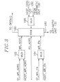
- FIG. 3 there is a block diagram of the memory and I/O unit 150 shown in Fig. 2.
- HOST_DATA denotes the initial constant values which are used in performing the equations at the arithmetic unit 130.
- BIT_RATE, PICTURE_RATE, K p and K b in Eqs. 4A to 4C, initial constant values of X i , X p , X b , R, N p , N b , d 0 i , d 0 p and d 0 b at the start of encoding process are examples of such initial constants provided as HOST_DATA. They are provided from the host processor which serves to store and provide the various initial constant values which are predetermined according to, e.g., a system design.
- the calculation result obtained at the arithmetic unit 130 are also fed to the MUX 166 via L50 and stored at the RAM 160.
- Examples of such calculation results are R, N p , N b , T i , T p , T b and so forth.
- R is the remaining number of bits assigned to the current GOP determined as specified by Eq. (5), which is stored in the RAM 160 and updated at the arithmetic unit 130 after a frame is encoded.
- N p and N b are the respective numbers of P and B pictures remaining in the current GOP, which are used in calculating the target bit number T i , T p and T b according to Eqs. 4A to 4C.
- the temporary values obtained in the course of calculating Eqs. 1A, 1B, 9, 10 and 11 and obtained by calculating Eqs. 2A and 2B are also provided to the RAM 160, to be stored therein, as will be explained with reference to Fig. 12.
- ST_WR_ADRS and HOST_WR_ADRS are address signals used to write data, i.e., data from the arithmetic unit 130 inputted via the MUX 166 and HOST_DATA, to the RAM 160, respectively.
- ST_WR_EN and HOST_WR_EN are enable signals which go to active state when data is written to the RAM 160.
- MUXes 162, 164 and 166 select HOST_WR_ADRS, HOST_WR_EN and HOST_DATA, respectively, HOST_WR _ADRS denoting the address of the RAM 160 where the initial constant value is to be stored and HOST_WR_EN being an active state.
- the MUXes 162, 164 and 166 select ST_WR_ADRS, ST_WR_EN and data on L50, respectively, ST_WR_ADRS denoting the address of the RAM 160 where the calculation result is to be stored and ST_WR_EN being an active state.
- RD_ADRS is an address signal used to read data stored at the RAM 160 and to provide it either to the arithmetic unit 130, or the DPCM or Q block shown in Fig. 1. Specifically, the initial constant values, the temporary values and the result determined at the arithmetic unit 130 are read from the RAM 160 and provided back to the arithmetic unit 130 via L60. Meanwhile, the final results of three kinds of decisions, that is, the inter/intra and the field/frame DCT modes and the quantization parameter decision results Mquant m , are fed to the DPCM and Q blocks shown in Fig. 1.
- ST_WR_ADRS, HOST_WR_ADRS, RD_ADRS, ST_WR_EN and HOST_WR_EN explained above are part of the control sequence provided via L80 from the state machine 120.
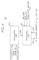
- FIG. 4 there is provided a block diagram of the arithmetic unit 130 shown in Fig. 2, which includes a calculating unit 140 and a processing unit 180.
- the calculating unit 140 receives the differential and the current frame data provided from the DPCM block 20 and provides a first set of temporary values to the processing unit 180.
- the differential and the current frame data are provided in pairs. That is, values of two neighboring pixels in a same line are provided during a same clock cycle.
- O(2i,j) and O(2i+1,j) denoting pixel values of the current frame data and D(2i,j) and D(2i+1,j) denoting pixel values of the differential frame data are such pairs, wherein i and j being integers denoting the position of the pixels in a frame.
- the first set of temporary values provided from the calculating unit 140 to the processing unit 180 will be explained with reference to Figs. 5 to 9 and 11.
- MB_NUM, BUF_FULL and the control sequence are fed to the processing unit 180 from the controlling unit 110, the buffer 60, and the state machine 120, respectively.
- the processing unit 180 are also coupled to the memory and I/O unit 150 so that it receives therefrom or provides thereto various data, such as the calculation result and the initial constant.
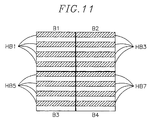
- the first set of temporary values are such values as are obtained by summing values related to pixel values, e.g., squares of pixel values or differences between two pixel values, for a half-block, a block, or a macroblock, wherein the half-block refers to 4 odd numbered lines or 4 even numbered lines as shown in Fig. 11.
- FIG. 11 there is shown an exemplary structure of a macroblock which includes 4 frame-organized blocks (B1 to B4), each block including 2 half-blocks.
- B1, B2, B3 and B4 include HB1 (half-blockl) and HB2; HB3 and HB4; HB5 and HB6; and HB7 and HB8, respectively, wherein each of odd numbered half-blocks (HB1, HB3, HB5, HB7) contains odd numbered lines (line1, line3, line5, line7) and each of even numbered half-blocks (HB2, HB4, HB6, HB8) contains even numbered lines (line2, line4, line6, line8).
- the macroblock may also be structured to include 4 field-organized blocks (B5 to B8, not shown), wherein B5, B6, B7 and B8 include HB1 and HB5; HB2 and HB6; HB3 and HB7; and HB4 and HB8, respectively.
- An original variance calculation block 200 and a half-block accumulation block 300 provide the temporary values on a half-block basis; a differential variance calculation block 600 provides the temporary value on a block-by-block basis; and a frame and a field variance calculation blocks 400 and 500 provide the temporary values on a macroblock basis.
- the original variance calculation block 200 provides var_org(k), k being an index identifying a half-block included in a macroblock and ranging from 1 to MK, MK being the number of half-blocks included in a macroblock, e.g., 8, wherein the var_org(k) is a sum of squares of, e.g., 32, pixel values included in a k-th half-block contained in a macroblock of the current frame data.
- the differential variance calculation block 600 provides var_dif(l), i.e., a sum of squares of, e.g., 64, pixel values included in an l-th block contained in a macroblock of the differential frame data, l being an index identifying a frame-organized block included in a macroblock and ranging from 1 to, e.g., 4.
- var_dif(l) i.e., a sum of squares of, e.g., 64, pixel values included in an l-th block contained in a macroblock of the differential frame data
- l being an index identifying a frame-organized block included in a macroblock and ranging from 1 to, e.g., 4.
- the half-block accumulation block 300 supplies sum(k), i.e., a sum of, e.g., 32, pixel values included in each half-block of the current frame data, to the processing unit 180.
- Eqs. (1A), (1B) and (10) may be modified as follows: wherein 11 is an index identifying a frame-organized or a field-organized block and ranging between 1 and ML, ML being a number of the blocks (including frame-organized and field-organized blocks) contained in a macroblock, e.g., 8; and the summations in Eq. (10') are performed for half-blocks included in the 11-th block.
- Eq. (1A), (1B) and (10) may be modified as follows: wherein 11 is an index identifying a frame-organized or a field-organized block and ranging between 1 and ML, ML being a number of the blocks (including frame-organized and field-organized blocks) contained in a macroblock, e.g., 8; and the summations in Eq. (10') are performed for half-blocks included in the 11-th block.
- the frame and the field variance calculation blocks 400 and 500 provide VAR_FRM and VAR_FLD according to Eqs. (2A) and (2B).
- the first set of temporary values including var_dif(l), the var_org(k), the sum(k), the VAR_FRM, and the VAR_FLD are provided to the processing unit 180, to be used in the inter/intra and the field/frame DCT mode and the quantization parameter decisions.
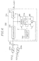
- FIG. 6 there is shown a block diagram of the original variance calculation block 200 which includes two squaring block 220a and 220b, an adder 230 and a half-block accumulation circuit 205.
- the current frame data (O(2i,j), O(2i+l,j)) is provided to the original variance calculation block 200 in the form of frame-organized blocks
- two var_org(k)'s of two half-blocks included in a frame-organized block are provided after pixel values included in the frame-organized block are inputted thereto.
- delay blocks 270a and 270b and a content of a counter circuit 290 are initialized to 0.
- O(0,0) and O(1,0) are squared at the squaring blocks 220a and 220b, respectively, and added at the adder 230.
- the squared sum, O(0,0) 2 + O(1,0) 2 is added to 0 provided through a multiplexor("MUX") 280 from the delay block 270a and the result is provided back through a demultiplexor("DEMUX”) 260 to the delay block 270a.
- O(2,0) and O(3,0) are squared and added, and then added to O(0,0) 2 + O(0,0) 2 provided from the delay block 270a.
- the counter circuit 290 controls the DEMUX 260 to provide an input thereto to the delay block 270a and controls the MUX 280 to select an input provided from the delay block 270a.
- a sum of squares of, e.g., 8, pixel values included in the first line is stored at the delay block 270a.
- a sum of squares of, e.g., 8, pixel values included in a second line is obtained and stored at the delay block 270b.
- the counter circuit 290 controls the DEMUX 260 and the MUX 280 so that the delay block 270b is utilized.
- sums of squares of pixels included in odd-numbered and even-numbered lines are added to the contents of the delay blocks 270a and 270b, respectively, to provide var_org(1) and var_org(2) to a memory 250.
- the var_org(1) is provided from the accumulator 240 to the memory 250; and after O(6,7) 2 + O(7,7) 2 is added to the contents of the delay block 270b, the var_org(2) is provided from the accumulator 240 to the memory 250.
- the memory 250 provides the var_org(1) and the var_org(2) to the processing unit 180.
- a block diagram of the differential variance calculation block 600 which provides the var_dif(1), being an index identifying a frame-organized block included in a macroblock. Unlike the original variance calculation block 200, it provides a sum of squares of all pixel values included in a frame-organized block.
- contents of a delay block 650 and a counter 670 are initialized with 0.
- Differential data D(0,0) and D(1,0) are inputted to absolute value blocks 610a and 610b wherein signs thereof are removed. By doing this, two squaring block 620a and 620b can be easily implemented as they need not deal with signed values.
- D(0,0) 2 and D(1,0) 2 provided from the squaring blocks 620a and 620b are added at an adder 630, then, added to 0 provided from the delay block 650 at an accumulator 640, to provide the result back to the delay block 650. Then, D(2,0) 2 and D(3,0) 2 are added at the adder 630 and summed to D(0,0) 2 + D(1,0) 2 provided from the delay block 650 at the accumulator 640, to provide the result back to the delay block 650.
- the var_dif(1) is stored at a memory 660 in response to a control signal provided from the counter 670 and provided to the processing unit 180.
- a block diagram of the half-block accumulation block 300 which supplies the sum(k), i.e., a sum of pixel values included in a half-block k. It includes an adder 330 and a half-block accumulation circuit 305 which is identical in structure to the one shown in Fig. 6. Therefore, the operation of the half-block accumulation block 300 is essentially same as that of the original variance calculation block 200 except that pixel values instead of squares of them are accumulated therein.
- a sums of pixel values of two half-blocks included therein i.e., sum(k) and sum(k+1), k being (2l-1) are provided from a memory 350 to the processing unit 180.
- FIG. 9 there is shown a block diagram of the frame variance calculation block 400 which provides the VAR_FRM. It includes two delay blocks 410a and 410b, two buffers 412a and 412b, a controller 413, two MUXes 414a and 414b, two subtractors 416a and 416b and a squaring and accumulating circuit 405.
- the structure of the squaring and accumulating circuit 405 is identical to the differential variance calculation block 600 shown Fig. 7 and the operation thereof is similar, too.
- Each of the delay blocks 410a and 410b is a line delay for delaying input thereto by a line of a block, e.g., 8 clock cycles.
- Each of the buffers 412a and 412b can store one line of a block, e.g., 8 pixel values.
- the VAR_FRM is determined on a macroblock basis.
- the current frame data is provided on a block-by-block basis. Therefore, Eq. (1A) is divided into following 6 sub-equations to conform to the input data format.
- O B1 (i,j), O B2 (i,j), O B3 (i,j) and O B4 (i,j) are pixel values included in the frame-organized blocks B1, B2, B3 and B4, respectively.
- Pixel values included in B1 is inputted to the delay blocks 410a and 410b wherein they are delayed for, e.g., 8 clock cycles. Therefore, when O(0,0) and O(1,0) are fed through the MUXes 414a and 414b to the subtractors 416a and 416b, respectively, O(0,1) and O(1,1) are fed to the subtractors 416a and 416b, to thereby provide the differences therebetween to absolute value blocks 418a and 418b, respectively. In this manner, while second to eighth lines of B1 are provided to the frame variance calculation block 400, the differences between two consecutive lines of B1 are added and accumulated at the squaring and accumulating block 405, to provide VAR_FRM(1) of Eq.
- the frame variance calculating block 400 calculates VAR_FRM(2) according to Eq. (2A-2). It should be noted that while a first line of B1 or B2 is inputted to the frame variance calculating block 400, the squaring and accumulating operation is not performed.
- a last line of B2 is stored at the buffers 412a and 412b in response to the control signal provided from the controller 413; O B2 (0,7), O B2 (2,7), O B2 (4,7) and O B2 (6,7) are stored at the buffer 412a and O B2 (1,7), O B2 (3,7), O B2 (5,7) and O B2 (7,7) are stored at the buffer 412b.
- O B2 (0,7), O B2 (2,7), O B2 (4,7) and O B2 (6,7) are stored at the buffer 412a and O B2 (1,7), O B2 (3,7), O B2 (5,7) and O B2 (7,7) are stored at the buffer 412b.
- the differences between the last line of B1 and the first line of B3 are squared and summed, to thereby provide VAR_FRM(3).
- the MUXes 414a and 414b select and provide O B1 (i,7)'s provided from the buffers 412a and 412b, to the subtractors 416a and 416b in response to control signals provided from the controller 413.
- the frame variance calculating block 400 calculates VAR_FRM(4); while a first line of B4 is inputted, the differences between the last line of B2 and the first line of B4 are squared and summed, to thereby provide VAR_FRM(5); and while receiving second to seventh lines of B4, the frame variance calculating block 400 calculates the VAR_FRM.
- the controller 413 provides various control signals.
- the controller 413 provides write and read address signals and a write enable signal, to the buffers 412a and 412b and supplies selection signals to the MUXes 414a and 414b so that the MUXes 414a and 414b selects pixel values provided from the buffers 412a and 412b while calculating VAR_FRM(3) and VAR_FRM(5) and selects inputs provided from the delay blocks 410a and 410b while calculating VAR_FRM(1), VAR_FRM(2), VAR_FRM(4), VAR_FRM(6).
- a block diagram of the field variance calculation block 500 (not shown) and operation thereof are similar to that of the frame variance calculation block 400.
- each of the delay blocks included in the field variance calculation block 500 is a line delay for delaying input thereto by two lines of a block, e.g., 16 clock cycles; and each of the buffers therein can store 2 lines of a block, e.g., 16 pixel values.
- FIG. 12 there is provided a block diagram of the processing unit 180 shown in Fig. 4.
- MB_NUM and BUF_FULL are fed to a MUX 182a from the controlling unit 110 and the buffer 60, respectively.
- the first set of temporary values provided from the calculating unit 140 is also fed to the MUX 182a.
- the initial constant values and the temporary values are provided from the memory and I/O unit 150 via L60, more specifically, from the RAM 160 shown in Fig. 3.
- FR_EXT_SEL, REG_EN_X, REG_EN_Y, CIN, OPERATION_SEL, FEED_BACK_SEL, DIV_START, QUOT_EN, TO_RAM_SEL, WINDOW_PNT and FR_RAM_PNT are control signals which are included in the control sequence provided from the state machine 120 shown in Fig. 2.
- the various elements of the processing unit 180 shown in Fig. 4 are controlled to perform arithmetic tasks according to the control sequence. The function of the control signals will now be presented.
- the VAR_ORG may be calculated according to following steps:
Landscapes
- Engineering & Computer Science (AREA)
- Multimedia (AREA)
- Signal Processing (AREA)
- Physics & Mathematics (AREA)
- General Physics & Mathematics (AREA)
- Discrete Mathematics (AREA)
- Theoretical Computer Science (AREA)
- Computing Systems (AREA)
- Compression Or Coding Systems Of Tv Signals (AREA)
- Compression, Expansion, Code Conversion, And Decoders (AREA)
Applications Claiming Priority (2)
| Application Number | Priority Date | Filing Date | Title |
|---|---|---|---|
| KR9561378 | 1995-12-28 | ||
| KR1019950061378A KR970057947A (ko) | 1995-12-28 | 1995-12-28 | 영상 부호화기에서의 타입 결정 및 버퍼 제어 장치 |
Publications (2)
| Publication Number | Publication Date |
|---|---|
| EP0782344A2 true EP0782344A2 (fr) | 1997-07-02 |
| EP0782344A3 EP0782344A3 (fr) | 1999-05-19 |
Family
ID=19445887
Family Applications (1)
| Application Number | Title | Priority Date | Filing Date |
|---|---|---|---|
| EP19960309553 Withdrawn EP0782344A3 (fr) | 1995-12-28 | 1996-12-30 | ContrÔleur pour un système de codage d'un signal vidéo |
Country Status (5)
| Country | Link |
|---|---|
| US (1) | US5949488A (fr) |
| EP (1) | EP0782344A3 (fr) |
| JP (1) | JPH09200761A (fr) |
| KR (2) | KR970057947A (fr) |
| CN (1) | CN1159123A (fr) |
Cited By (5)
| Publication number | Priority date | Publication date | Assignee | Title |
|---|---|---|---|---|
| EP0982951A1 (fr) * | 1998-08-28 | 2000-03-01 | THOMSON multimedia | Procédé de compression d'images |
| FR2857205A1 (fr) * | 2003-07-04 | 2005-01-07 | Nextream France | Dispositif et procede de codage de donnees video |
| EP1365596A3 (fr) * | 2002-04-30 | 2005-04-06 | Sony Corporation | Appareil et méthode de traitement d'image |
| FR2899743A1 (fr) * | 2006-04-11 | 2007-10-12 | Vixs Systems Inc | Systeme de pre-traitement de donnees intra-images |
| US7609766B2 (en) | 2005-02-08 | 2009-10-27 | Vixs Systems, Inc. | System of intra-picture complexity preprocessing |
Families Citing this family (10)
| Publication number | Priority date | Publication date | Assignee | Title |
|---|---|---|---|---|
| KR100588795B1 (ko) * | 1997-12-08 | 2006-06-13 | 소니 가부시끼 가이샤 | 부호화 장치 및 부호화 방법 |
| GB2337392B (en) * | 1997-12-08 | 2002-04-17 | Sony Corp | Coding device and method |
| JP2005202248A (ja) * | 2004-01-16 | 2005-07-28 | Fujitsu Ltd | オーディオ符号化装置およびオーディオ符号化装置のフレーム領域割り当て回路 |
| CN101677402B (zh) * | 2004-09-16 | 2012-04-18 | 汤姆逊许可证公司 | 用于快速视频帧和场编码的方法和装置 |
| KR100657314B1 (ko) * | 2005-05-04 | 2006-12-20 | 삼성전자주식회사 | 멀티미디어 스트리밍 송신 장치 및 방법 |
| US20070192393A1 (en) * | 2006-02-14 | 2007-08-16 | Taiyi Cheng | Method and system for hardware and software shareable DCT/IDCT control interface |
| JP5017555B2 (ja) * | 2006-04-10 | 2012-09-05 | 株式会社メガチップス | 画像符号化装置及び画像復号化装置 |
| KR101457418B1 (ko) | 2009-10-23 | 2014-11-04 | 삼성전자주식회사 | 계층적 부호화 단위의 크기에 따른 비디오 부호화 방법과 그 장치, 및 비디오 복호화 방법과 그 장치 |
| US8975851B2 (en) * | 2011-03-29 | 2015-03-10 | Advics Co., Ltd. | Temperature estimating device and temperature estimating method |
| JP5760950B2 (ja) * | 2011-10-28 | 2015-08-12 | 富士通株式会社 | 動画像再符号化装置、動画像再符号化方法及び動画像再符号化用コンピュータプログラム |
Family Cites Families (19)
| Publication number | Priority date | Publication date | Assignee | Title |
|---|---|---|---|---|
| CA1311063C (fr) * | 1988-12-16 | 1992-12-01 | Tokumichi Murakami | Processeur de signaux numeriques |
| DE69032177T2 (de) * | 1989-12-25 | 1998-11-12 | Mitsubishi Electric Corp | Kodierungsgerät |
| US5268755A (en) * | 1991-02-21 | 1993-12-07 | Matsushita Electric Industrial Co., Ltd. | Orthogonal transformation encoder |
| US5347309A (en) * | 1991-04-25 | 1994-09-13 | Matsushita Electric Industrial Co., Ltd. | Image coding method and apparatus |
| US5317397A (en) * | 1991-05-31 | 1994-05-31 | Kabushiki Kaisha Toshiba | Predictive coding using spatial-temporal filtering and plural motion vectors |
| JP2991833B2 (ja) * | 1991-10-11 | 1999-12-20 | 松下電器産業株式会社 | インターレス走査ディジタルビデオ信号の符号化装置及びその方法 |
| US5144424A (en) * | 1991-10-15 | 1992-09-01 | Thomson Consumer Electronics, Inc. | Apparatus for video data quantization control |
| US5231484A (en) * | 1991-11-08 | 1993-07-27 | International Business Machines Corporation | Motion video compression system with adaptive bit allocation and quantization |
| US5227878A (en) * | 1991-11-15 | 1993-07-13 | At&T Bell Laboratories | Adaptive coding and decoding of frames and fields of video |
| JPH05167998A (ja) * | 1991-12-16 | 1993-07-02 | Nippon Telegr & Teleph Corp <Ntt> | 画像の符号化制御処理方法 |
| JP2551305B2 (ja) * | 1992-09-11 | 1996-11-06 | 日本電気株式会社 | 動画像符号化制御方式 |
| US5426463A (en) * | 1993-02-22 | 1995-06-20 | Rca Thomson Licensing Corporation | Apparatus for controlling quantizing in a video signal compressor |
| TW301098B (fr) * | 1993-03-31 | 1997-03-21 | Sony Co Ltd | |
| JP3442783B2 (ja) * | 1993-06-08 | 2003-09-02 | ソニー株式会社 | 符号化装置及び方法 |
| BE1007807A3 (nl) * | 1993-11-30 | 1995-10-24 | Philips Electronics Nv | Inrichting voor het coderen van een videosignaal. |
| US5654760A (en) * | 1994-03-30 | 1997-08-05 | Sony Corporation | Selection of quantization step size in accordance with predicted quantization noise |
| JP3954656B2 (ja) * | 1994-09-29 | 2007-08-08 | ソニー株式会社 | 画像符号化装置及び方法 |
| JPH08256341A (ja) * | 1995-03-17 | 1996-10-01 | Sony Corp | 画像信号符号化方法、画像信号符号化装置、画像信号記録媒体、及び画像信号復号化装置 |
| KR0153671B1 (ko) * | 1995-06-30 | 1998-11-16 | 배순훈 | 고선명 텔레비젼 엔코더의 레이트 콘트롤러 |
-
1995
- 1995-12-28 KR KR1019950061378A patent/KR970057947A/ko active Pending
-
1996
- 1996-12-27 CN CN96114187A patent/CN1159123A/zh active Pending
- 1996-12-27 JP JP34914796A patent/JPH09200761A/ja active Pending
- 1996-12-27 US US08/774,832 patent/US5949488A/en not_active Expired - Fee Related
- 1996-12-28 KR KR1019960075569A patent/KR100269424B1/ko not_active Expired - Fee Related
- 1996-12-30 EP EP19960309553 patent/EP0782344A3/fr not_active Withdrawn
Non-Patent Citations (1)
| Title |
|---|
| None |
Cited By (8)
| Publication number | Priority date | Publication date | Assignee | Title |
|---|---|---|---|---|
| EP0982951A1 (fr) * | 1998-08-28 | 2000-03-01 | THOMSON multimedia | Procédé de compression d'images |
| FR2782879A1 (fr) * | 1998-08-28 | 2000-03-03 | Thomson Multimedia Sa | Procede de compression d'images |
| EP1365596A3 (fr) * | 2002-04-30 | 2005-04-06 | Sony Corporation | Appareil et méthode de traitement d'image |
| FR2857205A1 (fr) * | 2003-07-04 | 2005-01-07 | Nextream France | Dispositif et procede de codage de donnees video |
| EP1494483A3 (fr) * | 2003-07-04 | 2005-01-19 | Nextream France | Codeur vidéo avec controle de la structure de GOP selon l'activité spatiale et temporelle |
| US7577196B2 (en) | 2003-07-04 | 2009-08-18 | Thomson Licensing | Device and method for coding video data |
| US7609766B2 (en) | 2005-02-08 | 2009-10-27 | Vixs Systems, Inc. | System of intra-picture complexity preprocessing |
| FR2899743A1 (fr) * | 2006-04-11 | 2007-10-12 | Vixs Systems Inc | Systeme de pre-traitement de donnees intra-images |
Also Published As
| Publication number | Publication date |
|---|---|
| KR970057912A (ko) | 1997-07-31 |
| EP0782344A3 (fr) | 1999-05-19 |
| KR100269424B1 (ko) | 2000-10-16 |
| US5949488A (en) | 1999-09-07 |
| CN1159123A (zh) | 1997-09-10 |
| KR970057947A (ko) | 1997-07-31 |
| JPH09200761A (ja) | 1997-07-31 |
Similar Documents
| Publication | Publication Date | Title |
|---|---|---|
| EP0751687B1 (fr) | Unité de commande pour un système de codage de signal vidéo | |
| US5949488A (en) | Video signal encoding system controller | |
| US6084636A (en) | Video signal encoding method and apparatus employing an adaptive quantization technique | |
| JP3533282B2 (ja) | 複数のプロセッサを使用したビデオ圧縮 | |
| EP0959627B1 (fr) | Mèthode et système de compression d'images vidéo animées avec allocation adaptive de bits et quantification | |
| JP3954656B2 (ja) | 画像符号化装置及び方法 | |
| EP0613306B1 (fr) | Appareil de contrÔle de quantification dans un compresseur de signal vidéo | |
| EP1063851B1 (fr) | Dispositif et procédé de codage de signaux d'image animée | |
| EP0685971B1 (fr) | Appareil de codage d'images vidéo comprenant plusieurs codeurs | |
| EP0562787A2 (fr) | Méthode et dispositif de codage d'image | |
| JPH05145773A (ja) | ビデオ画像の符号化装置と方法 | |
| EP0480353B1 (fr) | Méthode et dispositif de compression de données pour signal vidéo | |
| EP0987902B1 (fr) | Dispositif et procédé de codage | |
| JP3755155B2 (ja) | 画像符号化装置 | |
| EP0714212A2 (fr) | Décodeur vidéo employant traitement concurrent et partage de ressources | |
| US20050123038A1 (en) | Moving image encoding apparatus and moving image encoding method, program, and storage medium | |
| JPH09322176A (ja) | 符号化モード選択方法、動画像符号化装置、符号化方法、記録方法、及び伝送方法 | |
| US5751357A (en) | Method and arrangement for coding and decoding a video data stream for all picture elements of the video data stream | |
| JPH05227520A (ja) | 画像圧縮符号化装置 | |
| US7133448B2 (en) | Method and apparatus for rate control in moving picture video compression | |
| US20020106021A1 (en) | Method and apparatus for reducing the amount of computation of the video images motion estimation | |
| US20010014123A1 (en) | Method for processing video | |
| JPH08102965A (ja) | 画像符号化装置 | |
| JP3626779B2 (ja) | 画像符号化方法及び装置 | |
| KR100209417B1 (ko) | 비디오 신호 부호화 시스템 제어기 |
Legal Events
| Date | Code | Title | Description |
|---|---|---|---|
| PUAI | Public reference made under article 153(3) epc to a published international application that has entered the european phase |
Free format text: ORIGINAL CODE: 0009012 |
|
| AK | Designated contracting states |
Kind code of ref document: A2 Designated state(s): DE FR GB IT NL |
|
| PUAL | Search report despatched |
Free format text: ORIGINAL CODE: 0009013 |
|
| AK | Designated contracting states |
Kind code of ref document: A3 Designated state(s): DE FR GB IT NL |
|
| 17P | Request for examination filed |
Effective date: 19991117 |
|
| STAA | Information on the status of an ep patent application or granted ep patent |
Free format text: STATUS: THE APPLICATION HAS BEEN WITHDRAWN |
|
| 18W | Application withdrawn |
Withdrawal date: 19991214 |
|
| 17Q | First examination report despatched |
Effective date: 20000619 |