EP0782910A2 - Dispositif pour supporter une plaque à gaufrer dans un moule d'injection pour substrat de plaque optique - Google Patents
Dispositif pour supporter une plaque à gaufrer dans un moule d'injection pour substrat de plaque optique Download PDFInfo
- Publication number
- EP0782910A2 EP0782910A2 EP96810811A EP96810811A EP0782910A2 EP 0782910 A2 EP0782910 A2 EP 0782910A2 EP 96810811 A EP96810811 A EP 96810811A EP 96810811 A EP96810811 A EP 96810811A EP 0782910 A2 EP0782910 A2 EP 0782910A2
- Authority
- EP
- European Patent Office
- Prior art keywords
- plate
- stamper plate
- stamper
- cavity
- central hole
- Prior art date
- Legal status (The legal status is an assumption and is not a legal conclusion. Google has not performed a legal analysis and makes no representation as to the accuracy of the status listed.)
- Granted
Links
Images

Classifications
-
- B—PERFORMING OPERATIONS; TRANSPORTING
- B29—WORKING OF PLASTICS; WORKING OF SUBSTANCES IN A PLASTIC STATE IN GENERAL
- B29C—SHAPING OR JOINING OF PLASTICS; SHAPING OF MATERIAL IN A PLASTIC STATE, NOT OTHERWISE PROVIDED FOR; AFTER-TREATMENT OF THE SHAPED PRODUCTS, e.g. REPAIRING
- B29C45/00—Injection moulding, i.e. forcing the required volume of moulding material through a nozzle into a closed mould; Apparatus therefor
- B29C45/17—Component parts, details or accessories; Auxiliary operations
- B29C45/26—Moulds
- B29C45/263—Moulds with mould wall parts provided with fine grooves or impressions, e.g. for record discs
- B29C45/2632—Stampers; Mountings thereof
- B29C2045/2638—Magnetic means for mounting stampers
-
- B—PERFORMING OPERATIONS; TRANSPORTING
- B29—WORKING OF PLASTICS; WORKING OF SUBSTANCES IN A PLASTIC STATE IN GENERAL
- B29C—SHAPING OR JOINING OF PLASTICS; SHAPING OF MATERIAL IN A PLASTIC STATE, NOT OTHERWISE PROVIDED FOR; AFTER-TREATMENT OF THE SHAPED PRODUCTS, e.g. REPAIRING
- B29C45/00—Injection moulding, i.e. forcing the required volume of moulding material through a nozzle into a closed mould; Apparatus therefor
- B29C45/17—Component parts, details or accessories; Auxiliary operations
- B29C45/26—Moulds
- B29C45/263—Moulds with mould wall parts provided with fine grooves or impressions, e.g. for record discs
- B29C45/2632—Stampers; Mountings thereof
- B29C2045/264—Holders retaining the inner periphery of the stamper
-
- Y—GENERAL TAGGING OF NEW TECHNOLOGICAL DEVELOPMENTS; GENERAL TAGGING OF CROSS-SECTIONAL TECHNOLOGIES SPANNING OVER SEVERAL SECTIONS OF THE IPC; TECHNICAL SUBJECTS COVERED BY FORMER USPC CROSS-REFERENCE ART COLLECTIONS [XRACs] AND DIGESTS
- Y10—TECHNICAL SUBJECTS COVERED BY FORMER USPC
- Y10S—TECHNICAL SUBJECTS COVERED BY FORMER USPC CROSS-REFERENCE ART COLLECTIONS [XRACs] AND DIGESTS
- Y10S425/00—Plastic article or earthenware shaping or treating: apparatus
- Y10S425/033—Magnet
-
- Y—GENERAL TAGGING OF NEW TECHNOLOGICAL DEVELOPMENTS; GENERAL TAGGING OF CROSS-SECTIONAL TECHNOLOGIES SPANNING OVER SEVERAL SECTIONS OF THE IPC; TECHNICAL SUBJECTS COVERED BY FORMER USPC CROSS-REFERENCE ART COLLECTIONS [XRACs] AND DIGESTS
- Y10—TECHNICAL SUBJECTS COVERED BY FORMER USPC
- Y10S—TECHNICAL SUBJECTS COVERED BY FORMER USPC CROSS-REFERENCE ART COLLECTIONS [XRACs] AND DIGESTS
- Y10S425/00—Plastic article or earthenware shaping or treating: apparatus
- Y10S425/81—Sound record
Definitions
- the present invention relates to a stamper plate mounting device of an injection mold for an optical disc substrate for a CD-ROM or the like.
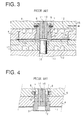
- FIG. 3 is a cross-sectional view illustrative of a conventional injection mold for optical disc substrates which is in the middle of an injection molding process, wherein the aforesaid camshaft is used to move the stamper plate holding bush.
- FIG. 4 is a schematic cross-sectional view illustrating the conventional injection mold wherein the stamper plate holding bush has been moved.
- the cavity side parts are placed, facing up; however, the metal mold may be placed sideways so that the central axis of the cavity may be horizontal, or it may also be placed upside down from that shown in the drawings.
- a retainer plate 6 is provided with a cavity side disc cavity plate 4.
- a hole 5 in which a stamper plate holding bush 2 is inserted.
- the bottom end of the stamper plate holding bush 2 is provided with a flange 3 which has a larger outside diameter than the central hole of the stamper plate 1.
- the top end of the stamper plate holding bush 2 is provided with notch 9.
- the retainer plate 6 rotatably supports two engaging rods 7 which engage with the aforesaid notch 9 of the bush 2.
- the two engaging rods 7, 7 respectively have planes 8, 8 of semicircular cross sections and they are connected so that they rotate in synchronization.
- a sprue bush 10 is inserted in the central hole in the stamper plate holding bush 2; it has an injection hole 11 for injecting melted resin at the center thereof.
- the cavity side disc cavity plate 4 is equipped with an annular cooling water channel 12 which is in contact with the retainer plate 6.
- Fixed on a movable retainer plate 19 is a movable disc cavity plate 17.
- a punch 18 for punching a central hole in a disc substrate is supported at the center of the movable disc cavity plate 17 in such a manner that it can move up and down in the drawing.
- the stamper plate 1 is fitted into the stamper plate holding bush 2 and the outer circumference of the hole of the stamper plate is held by the flange 3 of the bush 2.
- the bush 2 is retained by engagement with the planes 8, 8 of semicircular cross sections of the two engaging rods 7, 7 as shown in FIG. 3.
- the procedure for detaching the stamper plate 1 will be described.
- the mold is opened and a disc substrate molding 20 and the two engaging rods 7 are turned in the directions of the arrows as shown in FIG. 4.
- This releases the planes 8 of the engaging rods 7 from the notch 9 of the bush 2 for mounting the stamper plate, thus pushing the top surface thereof in the drawing.
- This in turn pushes the bush 2 for mounting the stamper plate out of the central hole 5 of the cavity side disc cavity plate 4 as illustrated, enabling an operator to manually remove the stamper plate 1 while holding the stamper plate holding bush 2.
- the example of the conventional stamper plate mounting device described above is designed to mechanically attach and detach the stamper plate 1 to and from the bush 2 for mounting the stamper plate, thus ensuring the attachment and detachment of the stamper plate.
- This design requires the use of the two rods 7, 7 and a device for driving them, thus posing the following problem.
- the use of the two rods and the provision of the driving device therefor in relation to a metal mold adversely affect the efforts made in achieving a smaller, lighter metal mold.
- providing the rods and the driving device therefor in relation to the metal mold unavoidably adds restrictions to the design of the cooling water channel and it also requires a certain level of skill for attaching and detaching the stamper plate.
- the stamper plate can be easily removed from the disc cavity plate by stopping vacuum suction.
- This metal mold has the following shortcoming: the cavity of the metal mold for injection-molding optical disc substrates is frequently put in a vacuum state by vacuum suction before filling the cavity with melted resin in order to improve the uniformity of the density of the melted resin charged in the cavity.
- the rear surface of the stamper plate and the cavity are vacuumized to the same level and the suction force on the rear surface of the stamper plate does not work.
- Another problem is the need for driving a vacuum pump at all times as long as a stamper plate is mounted even when molding operation is interrupted.
- the disc cavity plate uses martensite-based stainless steel which is subjected to heat treatment to hardness of H R C55 to 60 and further to corrosion-resistance treatment to hardness of H V 1800 or more in order to protect the surface of the disc cavity plate from scratches and corrosion.
- the roughness of the surface must be finished to 10 nm or less. Therefore, it is technically extremely difficult to satisfy the above requirements in embedding a soft magnet material in the surface of the disc cavity plate.
- the heat controlling technique including uniform cooling rate for the disc cavity plate is as important as the aforesaid selection of the material in ensuring the quality of the disc substrates. It is extremely difficult to assure satisfactory molding functions in the presence of the magnet or other between the cooling water channel provided at the back surface of the disc cavity plate and the surface of the disc cavity plate.
- stamper plate mounting device of an injection mold for an optical disc substrate which has a simple structure and which allows a stamper plate to be easily attached or detached without impairing the fundamental functions of a molding machine.
- a stamper plate mounting device of an injection mold for an optical disc substrate of an injection mold for an optical disc substrate
- the permanent magnet mentioned above is cylindrical and it is embedded in the other end surface of the means for holding the inner circumference of the stamper plate, so that it works on a bottom surface of the central hole of the aforesaid cavity plate.
- the permanent magnet can be buried in the bottom surface of the central hole 40 of the cavity plate so as to work on the other end surface of a means 45 for holding the inner circumference of the stamper plate.
- the magnet material for the permanent magnet may be of a neodymium (Ne-Fe-B) type, a samarium cobalt (Sm-Co) type, or alnico (Al-Ni-Co) type.
- the body of the means for holding the inner circumference of the stamper plate has an outside diameter surface which precisely fits into the central hole of the cavity plate; it may be provided with a flange which is larger than the aforesaid outside diameter surface.
- the means for holding the inner circumference of the stamper plate is constituted by an inner circumference bush and an outer circumference bush.
- One end of the inner circumference bush is provided with an outside diameter surface, which precisely fits in the central hole of the stamper plate, and a flange which is larger than the central hole of the stamper plate; the outer circumference is provided with an external thread.
- the outer circumference bush has an internal thread, which engages with the external thread and which is formed on the inner circumferential surface, and also the outside diameter surface which can be inserted in or withdrawn from the central hole of the cavity side disc cavity plate.
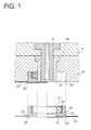
- FIG. 1 is a cross-sectional view of a first embodiment of a stamper plate mounting device of an injection mold for an optical disc substrate in accordance with the present invention.
- a state wherein the stamper plate has been attached is shown on the left side and whereas a state wherein the stamper plate has not yet been attached is shown on the right side.
- a hollow in the cavity is formed between a cavity side disc cavity plate 28 and a movable disc cavity plate (not shown) and melted resin is injected via the sprue bush 10, thereby injection-molding an optical disc substrate.
- the cavity side disc cavity plate 28 is provided on the retainer plate 6 and the hole 29 is provided at the center of the cavity side disc cavity plate 28.
- At least the bottom surface 30 and the circumferential surface of the hole must be composed of a ferromagnetic material.
- a cylindrical member 46, which supports the sprue bush 10 onto the cavity side disc cavity plate 28, is composed of a nonmagnetic material or a weak magnetic material, so that it exhibits higher magnetoresistance than the ferromagnetic material.
- the outside diameter surface 24 of the holding means is precisely fitted into the central hole 23 of the stamper plate 22 and the central hole 29 of the cavity side disc cavity plate 28.
- the other end of the means 21 for holding the inner circumference of the stamper plate is equipped with the cylindrical permanent magnet 27 which generates a magnetic flux applied to the bottom of the disc cavity.
- the permanent magnet 27 is, for example, an annular neodymium (Ne-Fe-B) permanent magnet; in the drawing, the north pole is on the upper side and the south pole is on the lower side in the drawing.
- the permanent magnet 27 is buried in the means 21 for holding the inner circumference of the stamper plate via a ferrite-based stainless bush, which is composed of a nonmagnetic material rather than a ferromagnetic material.
- a samarium cobalt (Sm-Co) type or alnico (Al-Ni-Co) type permanent magnet may be used in place of the neodymium type.
- the stamper plate 22 is first fitted onto the stamper plate mounting bush 21, then fitted in the central hole 29 of the disc cavity plate 28.
- the magnetic circuit generates attracting force between the means 21 for holding the inner circumference of the stamper plate and the cavity side disc cavity plate 28.
- a means for generating a magnetic force which is stronger than that of the permanent magnet 27 is actuated to apply the magnetic force to the means 21 for holding the inner circumference of the stamper plate so as to cancel the magnetic attraction between the means 21 for holding the inner circumference of the stamper plate and the bottom surface 30 of the cavity side disc cavity plate 28, thereby detaching the means 21.
- compressed air may be supplied between the means 21 for holding the inner circumference of the stamper plate and the cavity side disc cavity plate 28 in order to push the means 21 out.
- FIG. 2 is a cross-sectional view of a second embodiment of the stamper plate mounting device of the injection mold for the optical disc substrate in accordance with the present invention.
- the left half of the drawing shows a state wherein the stamper plate has been mounted.
- the hole 40 is provided at the center of the disc cavity plate 39.
- An annular permanent magnet 44 is disposed on a bottom surface 42 of the hole 40.
- the annular, cylindrical permanent magnet 44 made of neodymium (Ne-Fe-B) is buried in the bottom of the disc cavity plate 39 via a bush 43 composed of a nonmagnetic material.
- a samarium cobalt (Sm-Co) type or alnico (Al-Ni-Co) type permanent magnet may be used in place of the neodymium type.
- the means 45 for holding the inner circumference of the stamper plate is constituted by an inner circumference bush 33 and an outer circumference bush 37.
- One end of the inner circumference bush 33 is provided with an outside diameter surface 34, which precisely fits in the central hole 31 of the stamper plate 32, and the flange 35 which is larger than the central hole 31 of the stamper plate 32; the outer circumference is provided with the external thread 36.
- the outer circumference bush 37 is made of a ferromagnetic material; it has an internal thread 38, which engages with the external thread 36 and which is formed on the inner circumferential surface, and also the outside diameter surface 41 which can be inserted in or withdrawn from the central hole 40 of the cavity side disc cavity plate 39.
- the procedure for fitting the stamper plate 32 of this embodiment in the central hole 40 of the cavity side disc cavity plate 39 is as follows: firstly, the stamper plate 32 is fitted onto the outside diameter surface 34 of the inner circumference bush 33; secondly, the inner circumference bush 33 is attached to the outer circumference bush 37, then they are inserted in the central hole 40 of the cavity side disc cavity plate 39.
- This magnetic circuit generates attracting force between the means 45 for holding the inner circumference of the stamper plate and the cavity side disc cavity plate 29.
- the procedure for detaching the means 45 for holding the inner circumference of the stamper plate is the same as that for the first embodiment.
- the stamper plate mounting device of the injection mold for the optical disc in accordance with the present invention has the following advantages over the conventional stamper plate mounting device.
- the means for holding the inner circumference of the stamper plate, to which a stamper plate has been attached is securely held by the attraction given by the permanent magnet; therefore, the stamper plate does not come off as in the case of the example of the conventional vacuum suction type device.
- the present invention there is no need to change the material of the disc cavity plate or to modify the heat transfer structure thereof as in the conventional device since the magnet is not buried in the surface of the disc cavity plate which corresponds to the signal bit area of the stamper plate.
- the device according to the present invention does not require any mechanical driving system, thus making it possible to achieve a smaller, lighter metal mold and also to reduce the number of components.
- the stamper plate is mounted onto the cavity side disc cavity plate; however, the stamper plate may alternatively be mounted onto the movable disc cavity plate.
Landscapes
- Engineering & Computer Science (AREA)
- Manufacturing & Machinery (AREA)
- Mechanical Engineering (AREA)
- Moulds For Moulding Plastics Or The Like (AREA)
- Manufacturing Optical Record Carriers (AREA)
Applications Claiming Priority (3)
| Application Number | Priority Date | Filing Date | Title |
|---|---|---|---|
| JP331229/95 | 1995-11-28 | ||
| JP7331229A JPH09150438A (ja) | 1995-11-28 | 1995-11-28 | 光ディスク基盤射出成形金型のスタンパプレート装着装置 |
| JP33122995 | 1995-11-28 |
Publications (3)
| Publication Number | Publication Date |
|---|---|
| EP0782910A2 true EP0782910A2 (fr) | 1997-07-09 |
| EP0782910A3 EP0782910A3 (fr) | 1998-06-03 |
| EP0782910B1 EP0782910B1 (fr) | 2002-02-13 |
Family
ID=18241345
Family Applications (1)
| Application Number | Title | Priority Date | Filing Date |
|---|---|---|---|
| EP96810811A Expired - Lifetime EP0782910B1 (fr) | 1995-11-28 | 1996-11-19 | Dispositif pour supporter une plaque à gaufrer dans un moule d'injection pour substrat de plaque optique |
Country Status (3)
| Country | Link |
|---|---|
| US (1) | US5798122A (fr) |
| EP (1) | EP0782910B1 (fr) |
| JP (1) | JPH09150438A (fr) |
Cited By (1)
| Publication number | Priority date | Publication date | Assignee | Title |
|---|---|---|---|---|
| CN104354253A (zh) * | 2014-10-27 | 2015-02-18 | 苏州广型模具有限公司 | 一种高定位精度的分体模具 |
Families Citing this family (3)
| Publication number | Priority date | Publication date | Assignee | Title |
|---|---|---|---|---|
| US7150613B2 (en) * | 2004-05-24 | 2006-12-19 | Richter Precision Inc. | Contamination-free magnetic stamper holder |
| JP2009006615A (ja) * | 2007-06-28 | 2009-01-15 | Taiyo Yuden Co Ltd | 光ディスクおよび成形用金型装置 |
| US11618194B2 (en) * | 2018-03-13 | 2023-04-04 | Inglass S.P.A. | Apparatus for injection molding of plastic materials |
Citations (3)
| Publication number | Priority date | Publication date | Assignee | Title |
|---|---|---|---|---|
| JPH02295726A (ja) | 1989-05-09 | 1990-12-06 | Seiko Giken:Kk | ディスク成形金型装置 |
| JPH0260502B2 (fr) | 1985-07-01 | 1990-12-17 | Naguron Pureshijon Tooringu Bv | |
| JPH05185475A (ja) | 1992-01-08 | 1993-07-27 | Sony Corp | ディスク基板成形用金型装置 |
Family Cites Families (7)
| Publication number | Priority date | Publication date | Assignee | Title |
|---|---|---|---|---|
| US4907956A (en) * | 1988-04-27 | 1990-03-13 | Dainippon Ink And Chemicals, Inc. | Apparatus for manufacturing optical information recording medium |
| US5049053A (en) * | 1988-08-18 | 1991-09-17 | Hitachi Metals, Ltd. | Metal mold for molding anisotropic permanent magnets |
| JP2632382B2 (ja) * | 1988-08-25 | 1997-07-23 | 株式会社グリーン田中 | 砕土機 |
| US5112205A (en) * | 1989-05-15 | 1992-05-12 | Sony Corporation | Optical-disk manufacturing apparatus |
| US5326240A (en) * | 1991-10-12 | 1994-07-05 | Sony Corporation | Metal mold device for molding a disc substrate |
| US5427520A (en) * | 1992-01-31 | 1995-06-27 | Sony Corporation | Mold device for fabricating disc substrate |
| JP3140309B2 (ja) * | 1994-09-26 | 2001-03-05 | 株式会社名機製作所 | ディスク成形金型装置 |
-
1995
- 1995-11-28 JP JP7331229A patent/JPH09150438A/ja active Pending
-
1996
- 1996-08-28 US US08/704,321 patent/US5798122A/en not_active Expired - Fee Related
- 1996-11-19 EP EP96810811A patent/EP0782910B1/fr not_active Expired - Lifetime
Patent Citations (3)
| Publication number | Priority date | Publication date | Assignee | Title |
|---|---|---|---|---|
| JPH0260502B2 (fr) | 1985-07-01 | 1990-12-17 | Naguron Pureshijon Tooringu Bv | |
| JPH02295726A (ja) | 1989-05-09 | 1990-12-06 | Seiko Giken:Kk | ディスク成形金型装置 |
| JPH05185475A (ja) | 1992-01-08 | 1993-07-27 | Sony Corp | ディスク基板成形用金型装置 |
Cited By (1)
| Publication number | Priority date | Publication date | Assignee | Title |
|---|---|---|---|---|
| CN104354253A (zh) * | 2014-10-27 | 2015-02-18 | 苏州广型模具有限公司 | 一种高定位精度的分体模具 |
Also Published As
| Publication number | Publication date |
|---|---|
| EP0782910B1 (fr) | 2002-02-13 |
| EP0782910A3 (fr) | 1998-06-03 |
| US5798122A (en) | 1998-08-25 |
| JPH09150438A (ja) | 1997-06-10 |
Similar Documents
| Publication | Publication Date | Title |
|---|---|---|
| US5612062A (en) | Means for holding stamper plate in molding metal die | |
| EP0537953B1 (fr) | Dispositif de moule métallique pour mouler un substrat de disque | |
| US5691681A (en) | Method of producing a field magnet for a DC motor and a field magnet for a DC motor | |
| EP0782911B1 (fr) | Dispositif pour fixer/détacher des plaques à gaufrer dans un moule d'injection pour substrat de plaque optique | |
| EP0782910B1 (fr) | Dispositif pour supporter une plaque à gaufrer dans un moule d'injection pour substrat de plaque optique | |
| JP3898565B2 (ja) | 磁気吸着保持装置 | |
| SE9804324L (sv) | Solenoid med permanentmagnetankare samt förfarande för dess framställning | |
| JP3573410B2 (ja) | 型吸着装置を備えた型締装置 | |
| JP2666918B2 (ja) | 磁性体部品のインサート装置 | |
| JPH0872111A (ja) | 金型ロック装置 | |
| JP2005246448A (ja) | 鋳包み鋳造成形用の被鋳包み材及び鋳包み鋳造方法 | |
| JP7353681B2 (ja) | 交換自在な金型部品 | |
| JPS61273920A (ja) | インサ−トが埋設された成形品の射出成形法 | |
| JPS62234641A (ja) | 鋳造用中子の支持方法 | |
| JPH0857909A (ja) | 光ディスク基盤用成形型とそれに用いられるスタンパ着脱装置およびスタンパ装着方法 | |
| JP2003133126A (ja) | 磁石付き留め具 | |
| EP0974442B1 (fr) | Fabrication de supports d'information annulaires en forme de disque | |
| JPH037141Y2 (fr) | ||
| JPH01127303A (ja) | 樹脂成型用インサート部品の型内支持方法 | |
| JPH0387865A (ja) | 粉体貯蔵容器 | |
| JP2006231577A (ja) | 金型 | |
| JPH0719133Y2 (ja) | ボンド磁石用成形金型 | |
| JPH0857824A (ja) | 成形型の造型方法 | |
| JPH1080925A (ja) | 埋込み金物を有する成形品の製造方法と成形金型 | |
| JPH02213108A (ja) | 異方性多極プラスチック磁石の製造方法 |
Legal Events
| Date | Code | Title | Description |
|---|---|---|---|
| PUAI | Public reference made under article 153(3) epc to a published international application that has entered the european phase |
Free format text: ORIGINAL CODE: 0009012 |
|
| AK | Designated contracting states |
Kind code of ref document: A2 Designated state(s): CH LI NL |
|
| PUAL | Search report despatched |
Free format text: ORIGINAL CODE: 0009013 |
|
| AK | Designated contracting states |
Kind code of ref document: A3 Designated state(s): CH LI NL |
|
| 17P | Request for examination filed |
Effective date: 19980602 |
|
| GRAG | Despatch of communication of intention to grant |
Free format text: ORIGINAL CODE: EPIDOS AGRA |
|
| GRAG | Despatch of communication of intention to grant |
Free format text: ORIGINAL CODE: EPIDOS AGRA |
|
| GRAH | Despatch of communication of intention to grant a patent |
Free format text: ORIGINAL CODE: EPIDOS IGRA |
|
| 17Q | First examination report despatched |
Effective date: 20010625 |
|
| GRAH | Despatch of communication of intention to grant a patent |
Free format text: ORIGINAL CODE: EPIDOS IGRA |
|
| GRAA | (expected) grant |
Free format text: ORIGINAL CODE: 0009210 |
|
| AK | Designated contracting states |
Kind code of ref document: B1 Designated state(s): CH LI NL |
|
| REG | Reference to a national code |
Ref country code: CH Ref legal event code: EP |
|
| REG | Reference to a national code |
Ref country code: CH Ref legal event code: NV Representative=s name: BOVARD AG PATENTANWAELTE |
|
| PLBE | No opposition filed within time limit |
Free format text: ORIGINAL CODE: 0009261 |
|
| STAA | Information on the status of an ep patent application or granted ep patent |
Free format text: STATUS: NO OPPOSITION FILED WITHIN TIME LIMIT |
|
| 26N | No opposition filed |
Effective date: 20021114 |
|
| PGFP | Annual fee paid to national office [announced via postgrant information from national office to epo] |
Ref country code: CH Payment date: 20051108 Year of fee payment: 10 |
|
| PGFP | Annual fee paid to national office [announced via postgrant information from national office to epo] |
Ref country code: NL Payment date: 20051116 Year of fee payment: 10 |
|
| PG25 | Lapsed in a contracting state [announced via postgrant information from national office to epo] |
Ref country code: LI Free format text: LAPSE BECAUSE OF NON-PAYMENT OF DUE FEES Effective date: 20061130 Ref country code: CH Free format text: LAPSE BECAUSE OF NON-PAYMENT OF DUE FEES Effective date: 20061130 |
|
| PG25 | Lapsed in a contracting state [announced via postgrant information from national office to epo] |
Ref country code: NL Free format text: LAPSE BECAUSE OF NON-PAYMENT OF DUE FEES Effective date: 20070601 |
|
| REG | Reference to a national code |
Ref country code: CH Ref legal event code: PL |
|
| NLV4 | Nl: lapsed or anulled due to non-payment of the annual fee |
Effective date: 20070601 |