EP0782911A2 - Prägeplatten-Befestigungs/Lösungs-Einrichtung einer Spritzgussform für den Schichtträger einer optischen Platte - Google Patents
Prägeplatten-Befestigungs/Lösungs-Einrichtung einer Spritzgussform für den Schichtträger einer optischen Platte Download PDFInfo
- Publication number
- EP0782911A2 EP0782911A2 EP96810814A EP96810814A EP0782911A2 EP 0782911 A2 EP0782911 A2 EP 0782911A2 EP 96810814 A EP96810814 A EP 96810814A EP 96810814 A EP96810814 A EP 96810814A EP 0782911 A2 EP0782911 A2 EP 0782911A2
- Authority
- EP
- European Patent Office
- Prior art keywords
- cavity
- plate
- stamper
- ring
- disc
- Prior art date
- Legal status (The legal status is an assumption and is not a legal conclusion. Google has not performed a legal analysis and makes no representation as to the accuracy of the status listed.)
- Granted
Links
- 239000000758 substrate Substances 0.000 title claims abstract description 35
- 238000002347 injection Methods 0.000 title claims abstract description 30
- 239000007924 injection Substances 0.000 title claims abstract description 30
- 230000003287 optical effect Effects 0.000 title claims abstract description 30
- 230000005291 magnetic effect Effects 0.000 claims abstract description 7
- 239000000463 material Substances 0.000 claims description 9
- 229910000828 alnico Inorganic materials 0.000 claims description 8
- KPLQYGBQNPPQGA-UHFFFAOYSA-N cobalt samarium Chemical compound [Co].[Sm] KPLQYGBQNPPQGA-UHFFFAOYSA-N 0.000 claims description 8
- 229910000938 samarium–cobalt magnet Inorganic materials 0.000 claims description 8
- 229910052779 Neodymium Inorganic materials 0.000 claims description 5
- QEFYFXOXNSNQGX-UHFFFAOYSA-N neodymium atom Chemical compound [Nd] QEFYFXOXNSNQGX-UHFFFAOYSA-N 0.000 claims description 5
- 230000005294 ferromagnetic effect Effects 0.000 claims description 2
- 239000003302 ferromagnetic material Substances 0.000 claims description 2
- 229910052751 metal Inorganic materials 0.000 description 7
- 239000002184 metal Substances 0.000 description 7
- 238000000465 moulding Methods 0.000 description 7
- 238000000034 method Methods 0.000 description 5
- 239000011347 resin Substances 0.000 description 5
- 229920005989 resin Polymers 0.000 description 5
- 238000001746 injection moulding Methods 0.000 description 3
- PXHVJJICTQNCMI-UHFFFAOYSA-N Nickel Chemical compound [Ni] PXHVJJICTQNCMI-UHFFFAOYSA-N 0.000 description 2
- 230000008859 change Effects 0.000 description 2
- 238000004080 punching Methods 0.000 description 2
- 238000010276 construction Methods 0.000 description 1
- 238000001816 cooling Methods 0.000 description 1
- 239000000498 cooling water Substances 0.000 description 1
- 230000007797 corrosion Effects 0.000 description 1
- 238000005260 corrosion Methods 0.000 description 1
- 238000010586 diagram Methods 0.000 description 1
- 239000002889 diamagnetic material Substances 0.000 description 1
- 238000010438 heat treatment Methods 0.000 description 1
- 230000006872 improvement Effects 0.000 description 1
- 238000009434 installation Methods 0.000 description 1
- 229910000734 martensite Inorganic materials 0.000 description 1
- 229910052759 nickel Inorganic materials 0.000 description 1
- 230000035699 permeability Effects 0.000 description 1
- 230000035939 shock Effects 0.000 description 1
- 229910001220 stainless steel Inorganic materials 0.000 description 1
- 239000010935 stainless steel Substances 0.000 description 1
- 229910000859 α-Fe Inorganic materials 0.000 description 1
Images


Classifications
-
- B—PERFORMING OPERATIONS; TRANSPORTING
- B29—WORKING OF PLASTICS; WORKING OF SUBSTANCES IN A PLASTIC STATE IN GENERAL
- B29C—SHAPING OR JOINING OF PLASTICS; SHAPING OF MATERIAL IN A PLASTIC STATE, NOT OTHERWISE PROVIDED FOR; AFTER-TREATMENT OF THE SHAPED PRODUCTS, e.g. REPAIRING
- B29C45/00—Injection moulding, i.e. forcing the required volume of moulding material through a nozzle into a closed mould; Apparatus therefor
- B29C45/17—Component parts, details or accessories; Auxiliary operations
- B29C45/26—Moulds
- B29C45/263—Moulds with mould wall parts provided with fine grooves or impressions, e.g. for record discs
- B29C45/2632—Stampers; Mountings thereof
-
- B—PERFORMING OPERATIONS; TRANSPORTING
- B29—WORKING OF PLASTICS; WORKING OF SUBSTANCES IN A PLASTIC STATE IN GENERAL
- B29D—PRODUCING PARTICULAR ARTICLES FROM PLASTICS OR FROM SUBSTANCES IN A PLASTIC STATE
- B29D17/00—Producing carriers of records containing fine grooves or impressions, e.g. disc records for needle playback, cylinder records; Producing record discs from master stencils
- B29D17/005—Producing optically read record carriers, e.g. optical discs
-
- B—PERFORMING OPERATIONS; TRANSPORTING
- B29—WORKING OF PLASTICS; WORKING OF SUBSTANCES IN A PLASTIC STATE IN GENERAL
- B29C—SHAPING OR JOINING OF PLASTICS; SHAPING OF MATERIAL IN A PLASTIC STATE, NOT OTHERWISE PROVIDED FOR; AFTER-TREATMENT OF THE SHAPED PRODUCTS, e.g. REPAIRING
- B29C45/00—Injection moulding, i.e. forcing the required volume of moulding material through a nozzle into a closed mould; Apparatus therefor
- B29C45/17—Component parts, details or accessories; Auxiliary operations
- B29C45/26—Moulds
- B29C45/263—Moulds with mould wall parts provided with fine grooves or impressions, e.g. for record discs
- B29C45/2632—Stampers; Mountings thereof
- B29C2045/2638—Magnetic means for mounting stampers
-
- Y—GENERAL TAGGING OF NEW TECHNOLOGICAL DEVELOPMENTS; GENERAL TAGGING OF CROSS-SECTIONAL TECHNOLOGIES SPANNING OVER SEVERAL SECTIONS OF THE IPC; TECHNICAL SUBJECTS COVERED BY FORMER USPC CROSS-REFERENCE ART COLLECTIONS [XRACs] AND DIGESTS
- Y10—TECHNICAL SUBJECTS COVERED BY FORMER USPC
- Y10S—TECHNICAL SUBJECTS COVERED BY FORMER USPC CROSS-REFERENCE ART COLLECTIONS [XRACs] AND DIGESTS
- Y10S425/00—Plastic article or earthenware shaping or treating: apparatus
- Y10S425/033—Magnet
-
- Y—GENERAL TAGGING OF NEW TECHNOLOGICAL DEVELOPMENTS; GENERAL TAGGING OF CROSS-SECTIONAL TECHNOLOGIES SPANNING OVER SEVERAL SECTIONS OF THE IPC; TECHNICAL SUBJECTS COVERED BY FORMER USPC CROSS-REFERENCE ART COLLECTIONS [XRACs] AND DIGESTS
- Y10—TECHNICAL SUBJECTS COVERED BY FORMER USPC
- Y10S—TECHNICAL SUBJECTS COVERED BY FORMER USPC CROSS-REFERENCE ART COLLECTIONS [XRACs] AND DIGESTS
- Y10S425/00—Plastic article or earthenware shaping or treating: apparatus
- Y10S425/81—Sound record
Definitions
- the present invention relates to a stamper plate attaching/detaching device of an injection mold for an optical disc substrate for a CD-ROM or the like.
- FIG. 4 is a cross-sectional view of an essential section of an optical disc substrate injection mold which employs a conventional cavity ring.
- a stamper plate attaching/detaching device for the optical disc substrate injection mold holds the stamper plate by using the cavity ring and a means for holding the central hole of the stamper plate.
- a hole 5 for receiving a means 2 for holding the inner circumferential rim of the stamper plate is provided at the center of a cavity side disc cavity plate 4.
- the cavity side disc cavity plate 4 is fixed to a cavity side base plate 13.
- a sprue bush 8, which has a resin passage 9 at the center thereof, is provided at the center of the aforesaid members.
- the cylindrical body of the stamper plate holding means 2 is inserted in the central hole in the disc-shaped stamper plate 1 to receive the stamper plate 1 by a flange 3 of the stamper plate holding means 2.
- the stamper plate holding means 2 is inserted in the central hole 5 of the cavity side disc cavity plate 4 and fixed by a publicly known method.
- a cavity ring 6 is installed to the cavity side disc cavity plate 4 by mounting bolts 7. This procedure is reversed when detaching the stamper plate 1.
- a movable disc cavity plate 10 is fixed to a movable base plate 14.
- a punch 12 for punching a central hole in a disc substrate is inserted in a central hole 11 of the movable disc cavity plate 10.
- the conventional device stated above is designed to mechanically attach or detach the outer circumferential rim of the stamper plate 1 by installing or removing the cavity ring 6 by installing or removing the mounting bolts 7; it is extensively used because it enables the stamper plate 1 to be securely attached or detached, thus leading to high reliability.
- the stamper plate 1, however, must be attached or detached with the mold installed in a limited space in a molding machine. This makes it extremely difficult and also dangerous to detach or attach the stamper plate. Hence, there has been high demand for improvement.
- the disc cavity plate uses martensite-based stainless steel which is subjected to heat treatment to hardness of H R C 55 to 60 and also to corrosion-resistance treatment to hardness of H V 1800 or more in order to protect the surface of the disc cavity plate from scratches and corrosion.
- the roughness of the surface must be finished to 10 nm or less. Therefore, it is technically extremely difficult to satisfy the above requirements in embedding a soft magnet material in the surface of the disc cavity plate.
- the heat controlling techniques including the one for maintaining uniform cooling rate for the disc cavity plate is as important as the aforesaid selection of the material in ensuring the quality of the disc substrates. It is extremely difficult to assure satisfactory molding functions in the presence of the magnet or other between the cooling water channel provided at the back surface of the disc cavity plate and the surface of the disc cavity plate.
- stamper plate attaching/detaching device of an injection mold for an optical disc substrate which device features a simple construction and which permits easy installation and removal of the stamper plate without impairing the basic functions of a molding machine.
- a stamper plate attaching/detaching device of an injection mold for an optical disc substrate for supporting the stamper plate in a cavity which is formed by a cavity side disc cavity plate, a movable disc cavity plate, and a cavity ring; the stamper plate attaching/detaching device being equipped with:
- the stamper plate attaching/detaching device further comprises a stamper plate central hole holding means which holds the central hole rim of the stamper plate, which is pressed by the cavity ring against either disc cavity, against the disc cavity.
- the cavity ring is composed of a ferromagnetic material; it is provided with a hole which prevents the attractive force from being generated when it confronts any pair of the permanent magnets.
- the means for rotating the cavity ring is a rotating handle which is manually operated.
- the magnet material for the permanent magnets is of a neodymium (Ne-Fe-B) type, a samarium cobalt (Sm-Co) type, or an alnico (Al-Ni-Co) type.
- a stamper plate attaching/detaching device of the injection mold for the optical disc substrate for supporting the stamper plate in a cavity which is formed by a cavity side disc cavity plate, a movable disc cavity plate, and a cavity ring; the stamper plate attaching/detaching device being equipped with:
- the stamper plate attaching/detaching device further includes a stamper plate central hole rim holding means which holds the central hole rim of the stamper plate, which is pressed by the cavity ring against either disc cavity, against the disc cavity.
- the stamper plate attaching/detaching device further includes a ferromagnetic section which generates an attractive force when it confronts the permanent magnets of the cavity ring of the cavity side disc cavity plate and the movable disc cavity plate and a hole or a nonmagnetic section which prevents the attractive force from being generated when the cavity side disc cavity plate and the movable disc cavity plate confront the permanent magnet.
- the means for rotating the cavity ring is a rotating handle which is manually operated.
- the magnet material for the permanent magnets is of the neodymium (Ne-Fe-B) type, the samarium cobalt (Sm-Co) type, or the alnico (Al-Ni-Co) type.
- FIG. 1 is a cross-sectional view of an essential part of a mold which employs the stamper plate attaching/detaching device of an injection mold for an optical disc substrate in accordance with the present invention.
- Shown on the left side of the drawing is a state wherein a cavity ring has been installed on a cavity side disc cavity plate and the stamper plate has been attached.
- Shown on the right side of the drawing is a state wherein the cavity ring has been attached to a movable disc cavity plate and the mold is open for the stamper plate to be attached or detached.
- a cylindrical stamper plate holding means 2 is equipped with a body which is inserted in the central hole in a stamper plate 26 and a flange 3 which is larger than the central hole in the stamper plate 26.
- a cavity side disc cavity plate 15 is fixed to a cavity side base plate 24.
- a sprue bush 8 is provided at the center of the aforesaid components. Resin is injected into the cavity through an injection hole 9 for melted resin at the center of the sprue bush 8.
- a movable disc cavity plate 16 is provided on a movable base plate 25; a punch 12 for punching the central hole at the center of a disc substrate is inserted in the central hole of the movable disc cavity plate 25.
- a cavity ring 17 forms, in cooperation with the cavity side disc cavity plate 15 and the movable disc cavity 16, a cavity hollow for injection molding when the mold is clamped.
- the cavity ring 17 also serves to press the outer circumferential rim of the stamper plate against the cavity side cavity plate 15.
- the cavity ring 17 is provided with a handle 30 for moving the cavity ring 17 between a first angle position and a second angle position in relation to the cavity side disc cavity plate 15 and the movable disc cavity 16.
- the cavity ring 17 has an inside diameter 28 which is smaller than an outside diameter 27 of the stamper plate 26; it is rotatably fitted onto an outer circumferential stepped section 29 of the movable disc cavity plate 16.
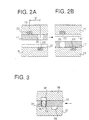
- FIG. 2A and 2B illustrate the relationship among the hole provided in the cavity ring 17, the cavity side disc cavity plate 15, the movable disc cavity plate 16, and the permanent magnets provided thereon.
- the angular positional relationship given in FIG. 2A corresponds to the state shown on the left side in FIG.1; the angular positional relationship given in FIG. 2B corresponds to the state shown on the right side in FIG. 1.
- Six blind holes 18 are provided along the same radial line at equal angles from the outer circumferential rim of the cavity side disc cavity plate 15 and six blind holes 19 are provided along the same radial line from the outer circumferential rim of the movable disc cavity plate 16 in such a manner that they face against the blind holes 18, the relative angles thereof being shifted by 15 degrees.
- the cavity ring 17 is also provided with six through holes 20 laid out along the same radial line.
- the disc cavity plates 15 and 16 respectively have six neodymium (Ne-Fe-B) rod-shaped permanent magnets 22 and 23 inserted in bushes 21 made of a nonmagnetic material such as ferrite-based stainless in the six blind holes 18 and 19, respectively, on the same radial line mentioned above. Shown at left in FIG. 1 is a state wherein the cavity ring 17 has been mounted on the cavity side disc cavity plate 15; shown at right in the same drawing is a state wherein the cavity ring 17 has been moved to the movable disc cavity plate 16.
- Ne-Fe-B neodymium
- An optical disc substrate is injection-molded while the outer circumferential rim of the stamper plate 26 is being pressed by the cavity ring 17 so that it is brought in close contact with the surface of the cavity side disc cavity plate 15. For this reason, the cavity ring 17 must be mounted and fixed onto the cavity side disc cavity plate 15. The stamper plate 26 cannot be removed with the cavity ring 17 mounted and fixed onto the cavity side disc cavity plate 15. Hence, the cavity ring 17 must be moved onto the movable disc cavity plate 16 first, then the mold is opened to take out the stamper plate 26.
- FIG. 2A and FIG.2B show the positional relationship between the respective permanent magnets and the holes when the cavity ring 17 is attached to the cavity side disc cavity plate 15 and the movable disc cavity plate 16, respectively.
- the rim surface portion except the through hole 20 of the cavity ring 17 overlaps the permanent magnet 22 of the cavity side disc cavity plate 15; the through hole 20 overlaps the permanent magnet 23 of the movable disc cavity plate 16.
- the through hole 20 is manually moved by the handle 30 of the cavity ring 17 to an angular position where it overlaps the permanent magnet 23 of the movable disc cavity plate 16.
- the attractive force given by the permanent magnet 22 of the cavity side disc cavity plate 15 causes the cavity ring 17 to be attracted and fixed to an outer circumferential stepped surface 31 of the cavity side disc cavity plate 15. At this time, the position of the permanent magnet 23 of the movable disc cavity plate 16 coincides with the position of the through hole of the cavity ring 17; therefore, the attractive force is not applied to the cavity ring 17.
- FIG. 2B Shown in FIG. 2B is the state wherein the cavity ring 17 has been moved from the cavity side disc cavity plate 15 to the movable disc cavity plate 16. More specifically, with the mold incompletely clamped with a gap of 0.5 mm or less still left, the cavity ring 17 is rotated manually in the opposite direction by the handle 30 so that the rim surface portion of the cavity ring 17 except the through hole 20 overlaps the permanent magnet 23 of the movable disc cavity plate 16 and the through hole 20 coincides with the position of the permanent magnet 22 of the cavity side disc cavity plate 15. This causes the cavity ring 17 to be attracted to the movable disc cavity plate 16 by the attractive force given by the permanent magnet 23 of the movable disc cavity plate 16.
- the attractive force of the permanent magnet 22 of the cavity side disc cavity plate 15 does not work on the surface of the cavity ring 17.
- the stoppers at both ends of rotational range of the cavity ring 17, a detent, and the like are provided according to a publicly known method although they are not shown.
- FIG. 2A Shown in FIG. 2A is the positional relationship established when the cavity ring 17 is in the first angle position. Under the positional relationship, an attractive force is generated between the permanent magnet 22 of the cavity side disc cavity plate 15 and the cavity ring 17, whereas no attractive force is generated between the permanent magnet 23 of the movable disc cavity plate 16 and the cavity ring 17.
- FIG. 2B Shown in FIG. 2B is the positional relationship established when the cavity ring 17 is in the second angle position. Under the positional relationship, no attractive force is generated between the permanent magnet 22 of the cavity side disc cavity plate 15 and the cavity ring 17, whereas the attractive force is generated between the permanent magnet 23 of the movable disc cavity plate 16 and the cavity ring 17.
- FIG. 3 is an explanatory diagram for illustrating the structure and operation of a second embodiment of the stamper plate attaching/detaching device of the injection mold for the optical disc substrate in accordance with the present invention.
- the basic structure of the mold to which the second embodiment is to be applied is identical to that described with reference to FIG. 1 and FIG. 4.
- Six permanent magnets 35 which have magnetic poles oriented in the vertical direction, are buried in the through holes in a cavity ring 32 via bushes 34 composed of a nonmagnetic material including a feeble or diamagnetic material.
- the cavity side disc cavity plate 36 and the movable disc cavity plate 37 are respectively provided with blind holes 38 and 39 which are shifted in phase against each other by 15 degrees.
- the procedure for attaching and detaching the stamper plate of the injection mold for the optical disc substrate is the same as that for the first embodiment.
- FIG. 3 shows a state wherein the cavity ring 32 is in the second angular position in relation to the cavity side disc cavity plate 36 and the movable disc cavity plate 37.
- no attractive force is generated between the cavity side disc cavity plate 36 and the permanent magnet 35, whereas the attractive force is generated between the movable disc cavity plate 37 and the permanent magnet 35.
- the cavity ring 32 is in the first angular position (not shown) in relation to the cavity side disc cavity plate 36 and the movable disc cavity plate 37, the attractive force is generated between the cavity side disc cavity plate 36 and the permanent magnet 35, whereas no attractive force is generated between the movable disc cavity plate 37 and the permanent magnet 35.
- the stamper plate does not come off as in the case of a vacuum suction type device.
- the present invention there is no need to change the material of the disc cavity plates or to add a change to the conventional heat transfer structure since the magnets are not buried in the surfaces of the disc cavity plates which correspond to the signal bit area of the stamper plate. This makes it possible to use the basic structure of a field-proven, reliable mold for the disc substrate.
- the stamper plate can be attached or detached quickly, securely and safely with the mold installed to the injection molding machine.
- the present invention can be embodied in other specific forms without departing from the spirit or essential characteristics thereof.
- the permanent magnets may be buried in both cavity plate and cavity ring so that the attractive force is generated when the surfaces of opposite poles face against each other and a repulsive force is generated when the surfaces of the same pole face against each other.
Landscapes
- Engineering & Computer Science (AREA)
- Mechanical Engineering (AREA)
- Manufacturing & Machinery (AREA)
- Moulds For Moulding Plastics Or The Like (AREA)
- Manufacturing Optical Record Carriers (AREA)
Applications Claiming Priority (3)
| Application Number | Priority Date | Filing Date | Title |
|---|---|---|---|
| JP33123095A JP3241983B2 (ja) | 1995-11-28 | 1995-11-28 | 光ディスク基盤射出成形金型用スタンパプレート着脱装置 |
| JP331230/95 | 1995-11-28 | ||
| JP33123095 | 1995-11-28 |
Publications (3)
| Publication Number | Publication Date |
|---|---|
| EP0782911A2 true EP0782911A2 (de) | 1997-07-09 |
| EP0782911A3 EP0782911A3 (de) | 1998-06-03 |
| EP0782911B1 EP0782911B1 (de) | 2002-02-13 |
Family
ID=18241358
Family Applications (1)
| Application Number | Title | Priority Date | Filing Date |
|---|---|---|---|
| EP96810814A Expired - Lifetime EP0782911B1 (de) | 1995-11-28 | 1996-11-21 | Prägeplatten-Befestigungs/Lösungs-Einrichtung einer Spritzgussform für den Schichtträger einer optischen Platte |
Country Status (3)
| Country | Link |
|---|---|
| US (1) | US6019587A (de) |
| EP (1) | EP0782911B1 (de) |
| JP (1) | JP3241983B2 (de) |
Cited By (1)
| Publication number | Priority date | Publication date | Assignee | Title |
|---|---|---|---|---|
| NL1007418C2 (nl) * | 1997-11-03 | 1999-05-04 | Od & Me Bv | Inrichting voor het vlak positioneren van een schijfvormig substraat alsmede een dergelijke werkwijze. |
Families Citing this family (8)
| Publication number | Priority date | Publication date | Assignee | Title |
|---|---|---|---|---|
| SE515607C2 (sv) * | 1999-12-10 | 2001-09-10 | Obducat Ab | Anordning och metod vid tillverkning av strukturer |
| US6830716B2 (en) * | 2001-06-06 | 2004-12-14 | Fuji Photo Film Co., Ltd. | Method of removing extraneous matter from injection mold |
| US6978976B2 (en) * | 2001-12-26 | 2005-12-27 | Callaway Golf Company | Magnetized core with pneumatic release system for creating a wax mold for a golf club head |
| US7144539B2 (en) * | 2002-04-04 | 2006-12-05 | Obducat Ab | Imprint method and device |
| FR2846663B1 (fr) | 2002-11-05 | 2006-08-11 | Rhodia Elect & Catalysis | Materiau transformant la lumiere, notamment pour parois de serres, comprenant comme additif un silicate de baryum et de magnesium |
| JP2006231577A (ja) * | 2005-02-22 | 2006-09-07 | Nidec Copal Corp | 金型 |
| US8641402B2 (en) * | 2011-09-09 | 2014-02-04 | Cheng Uei Precision Industry Co., Ltd. | Injection mold |
| JP6330965B1 (ja) * | 2017-11-10 | 2018-05-30 | Toto株式会社 | 成形装置 |
Citations (1)
| Publication number | Priority date | Publication date | Assignee | Title |
|---|---|---|---|---|
| JPH0260502B2 (de) | 1985-07-01 | 1990-12-17 | Naguron Pureshijon Tooringu Bv |
Family Cites Families (6)
| Publication number | Priority date | Publication date | Assignee | Title |
|---|---|---|---|---|
| EP0339616B1 (de) * | 1988-04-27 | 1997-01-08 | Dainippon Ink And Chemicals, Inc. | Vorrichtung zum Herstellen eines optischen Informations-Aufzeichnungsträgers |
| JP2632382B2 (ja) * | 1988-08-25 | 1997-07-23 | 株式会社グリーン田中 | 砕土機 |
| US5112205A (en) * | 1989-05-15 | 1992-05-12 | Sony Corporation | Optical-disk manufacturing apparatus |
| JP3252428B2 (ja) * | 1992-01-08 | 2002-02-04 | ソニー株式会社 | ディスク基板成形用金型装置 |
| US5326240A (en) * | 1991-10-12 | 1994-07-05 | Sony Corporation | Metal mold device for molding a disc substrate |
| JP3043606B2 (ja) * | 1995-10-25 | 2000-05-22 | 株式会社精工技研 | 成形金型内にスタンパプレートを保持する手段 |
-
1995
- 1995-11-28 JP JP33123095A patent/JP3241983B2/ja not_active Expired - Fee Related
-
1996
- 1996-09-26 US US08/721,026 patent/US6019587A/en not_active Expired - Fee Related
- 1996-11-21 EP EP96810814A patent/EP0782911B1/de not_active Expired - Lifetime
Patent Citations (1)
| Publication number | Priority date | Publication date | Assignee | Title |
|---|---|---|---|---|
| JPH0260502B2 (de) | 1985-07-01 | 1990-12-17 | Naguron Pureshijon Tooringu Bv |
Cited By (1)
| Publication number | Priority date | Publication date | Assignee | Title |
|---|---|---|---|---|
| NL1007418C2 (nl) * | 1997-11-03 | 1999-05-04 | Od & Me Bv | Inrichting voor het vlak positioneren van een schijfvormig substraat alsmede een dergelijke werkwijze. |
Also Published As
| Publication number | Publication date |
|---|---|
| JPH09150439A (ja) | 1997-06-10 |
| EP0782911A3 (de) | 1998-06-03 |
| US6019587A (en) | 2000-02-01 |
| EP0782911B1 (de) | 2002-02-13 |
| JP3241983B2 (ja) | 2001-12-25 |
Similar Documents
| Publication | Publication Date | Title |
|---|---|---|
| EP0537953B1 (de) | Metallische Formvorrichtung zum Formen eines Plattensubstrats | |
| EP0782911B1 (de) | Prägeplatten-Befestigungs/Lösungs-Einrichtung einer Spritzgussform für den Schichtträger einer optischen Platte | |
| JP3043606B2 (ja) | 成形金型内にスタンパプレートを保持する手段 | |
| US5691681A (en) | Method of producing a field magnet for a DC motor and a field magnet for a DC motor | |
| CA2142449A1 (en) | Molded Resin Motor Housing | |
| KR19990037283A (ko) | 툴 비트 자화 장치 및 방법 | |
| US11923135B2 (en) | Magnetic clamp device | |
| EP0782910B1 (de) | Prägeplatten-Halteeinrichtung einer Spritzgussform für den Schichtträger einer optischen Platte | |
| JP2005246634A (ja) | 射出成形機の金型固定装置 | |
| JP3573410B2 (ja) | 型吸着装置を備えた型締装置 | |
| JP3252428B2 (ja) | ディスク基板成形用金型装置 | |
| JPH0339813B2 (de) | ||
| JPH09307978A (ja) | 反発型磁気回路 | |
| JP2001256699A (ja) | デイスククランプ装置及びこれを備えるモータ | |
| JP3643242B2 (ja) | 交換媒体駆動装置 | |
| JPH01127303A (ja) | 樹脂成型用インサート部品の型内支持方法 | |
| JP2545157Y2 (ja) | 射出成形金型 | |
| JPH04244767A (ja) | 着磁ヨーク装置 | |
| KR960038755A (ko) | 헤드 드럼용 비디오 헤드의 스퍼터링 장치 | |
| JPH11265527A5 (de) | ||
| JPH11250508A (ja) | ディスク芯出し装置 | |
| JPS5951414B2 (ja) | 発泡成形機におけるブラケツト類の簡易脱着装置 | |
| JP2003133126A (ja) | 磁石付き留め具 | |
| GB1533860A (en) | Drive system for rotating a shaft | |
| JPH01318215A (ja) | 電磁石の製作方法 |
Legal Events
| Date | Code | Title | Description |
|---|---|---|---|
| PUAI | Public reference made under article 153(3) epc to a published international application that has entered the european phase |
Free format text: ORIGINAL CODE: 0009012 |
|
| AK | Designated contracting states |
Kind code of ref document: A2 Designated state(s): CH LI NL |
|
| PUAL | Search report despatched |
Free format text: ORIGINAL CODE: 0009013 |
|
| AK | Designated contracting states |
Kind code of ref document: A3 Designated state(s): CH LI NL |
|
| 17P | Request for examination filed |
Effective date: 19980602 |
|
| GRAG | Despatch of communication of intention to grant |
Free format text: ORIGINAL CODE: EPIDOS AGRA |
|
| GRAG | Despatch of communication of intention to grant |
Free format text: ORIGINAL CODE: EPIDOS AGRA |
|
| GRAH | Despatch of communication of intention to grant a patent |
Free format text: ORIGINAL CODE: EPIDOS IGRA |
|
| 17Q | First examination report despatched |
Effective date: 20010625 |
|
| GRAH | Despatch of communication of intention to grant a patent |
Free format text: ORIGINAL CODE: EPIDOS IGRA |
|
| GRAA | (expected) grant |
Free format text: ORIGINAL CODE: 0009210 |
|
| AK | Designated contracting states |
Kind code of ref document: B1 Designated state(s): CH LI NL |
|
| REG | Reference to a national code |
Ref country code: CH Ref legal event code: EP |
|
| REG | Reference to a national code |
Ref country code: CH Ref legal event code: NV Representative=s name: BOVARD AG PATENTANWAELTE |
|
| PLBE | No opposition filed within time limit |
Free format text: ORIGINAL CODE: 0009261 |
|
| STAA | Information on the status of an ep patent application or granted ep patent |
Free format text: STATUS: NO OPPOSITION FILED WITHIN TIME LIMIT |
|
| 26N | No opposition filed |
Effective date: 20021114 |
|
| PGFP | Annual fee paid to national office [announced via postgrant information from national office to epo] |
Ref country code: NL Payment date: 20061013 Year of fee payment: 11 |
|
| PGFP | Annual fee paid to national office [announced via postgrant information from national office to epo] |
Ref country code: CH Payment date: 20061108 Year of fee payment: 11 |
|
| PG25 | Lapsed in a contracting state [announced via postgrant information from national office to epo] |
Ref country code: LI Free format text: LAPSE BECAUSE OF NON-PAYMENT OF DUE FEES Effective date: 20071130 Ref country code: CH Free format text: LAPSE BECAUSE OF NON-PAYMENT OF DUE FEES Effective date: 20071130 |
|
| REG | Reference to a national code |
Ref country code: CH Ref legal event code: PL |
|
| NLV4 | Nl: lapsed or anulled due to non-payment of the annual fee |
Effective date: 20080601 |
|
| PG25 | Lapsed in a contracting state [announced via postgrant information from national office to epo] |
Ref country code: NL Free format text: LAPSE BECAUSE OF NON-PAYMENT OF DUE FEES Effective date: 20080601 |