EP0782920A2 - Contrepoids et mécanisme de levage - Google Patents
Contrepoids et mécanisme de levage Download PDFInfo
- Publication number
- EP0782920A2 EP0782920A2 EP96116475A EP96116475A EP0782920A2 EP 0782920 A2 EP0782920 A2 EP 0782920A2 EP 96116475 A EP96116475 A EP 96116475A EP 96116475 A EP96116475 A EP 96116475A EP 0782920 A2 EP0782920 A2 EP 0782920A2
- Authority
- EP
- European Patent Office
- Prior art keywords
- cylinder
- mechanism according
- support
- counterweight
- contact
- Prior art date
- Legal status (The legal status is an assumption and is not a legal conclusion. Google has not performed a legal analysis and makes no representation as to the accuracy of the status listed.)
- Granted
Links
Images


Classifications
-
- B—PERFORMING OPERATIONS; TRANSPORTING
- B41—PRINTING; LINING MACHINES; TYPEWRITERS; STAMPS
- B41F—PRINTING MACHINES OR PRESSES
- B41F13/00—Common details of rotary presses or machines
- B41F13/08—Cylinders
- B41F13/20—Supports for bearings or supports for forme, offset, or impression cylinders
-
- B—PERFORMING OPERATIONS; TRANSPORTING
- B41—PRINTING; LINING MACHINES; TYPEWRITERS; STAMPS
- B41P—INDEXING SCHEME RELATING TO PRINTING, LINING MACHINES, TYPEWRITERS, AND TO STAMPS
- B41P2227/00—Mounting or handling printing plates; Forming printing surfaces in situ
- B41P2227/20—Means enabling or facilitating exchange of tubular printing or impression members, e.g. printing sleeves, blankets
Definitions
- the present invention relates to a device for mounting a cylinder provided with a counterweight in a processing unit.
- US 4,458,591 discloses a rotary printing machine in which the angle between a blanket cylinder and a plate cylinder is changed by means of a tilting mechanism.
- a plate cylinder stop mechanism moves the plate cylinder to stop it from the blanket cylinder.
- a cam maintains the center-to-center distance between a forming roller and the plate cylinder.
- US 5,237,920 shows a device for mounting a cylinder in a printing unit of a rotary printing press.
- bearing parts can be removed from the ends of a printing unit cylinder.
- Counterweight devices are provided which comprise levers with an arcuate part, exert the force on the drive-side bearings of the printing couple cylinders and release the operator-side ends of the cylinders.
- Each of the counterweight devices comprises a toggle lever connection in order to move the respective lever into its setting position and to hold it in its setting position against the weight of the associated pressure cylinder.
- US 5,241,905 discloses a printing unit with a releasable bearing clamp.
- the printing unit comprises a gate which is rotatably mounted in a wall of a frame.
- the gate has a closed position in which it is above the opening in the frame wall and an open position in which it is not above the opening in the frame wall.
- a clamping mechanism is provided which clamps a bearing housing of a printing unit cylinder to the gate when it is closed Position.
- the clamping mechanism includes a first clamp attached to the gate and a second clamp mounted on the gate that moves to an open or closed position relative to the first clamp. In the closed position, the first clamp rests on the second clamp and is in engagement with the bearing housing of the printing unit cylinder. When the second clamp moves to the open position, the bearing housing is released. When the second clamp is in the open position, the gate moves to its open position, allowing access to the printing cylinder to replace a tubular sleeve. To shut down the printing unit cylinder, the gate can be moved together with
- US 5,301,609 discloses a printing unit with tilting and parking mechanisms.
- An upper and a lower support, which support the ends of the plate cylinders, are moved independently of one another in the transverse direction relative to a frame by a tilting mechanism.
- a shut-off mechanism comprises a pressure cylinder and a piston rod connected to the two carriers.
- the pressure cylinder and the piston rod are rotatably connected to the carriers and perform a rotational movement relative to the carriers when the carriers are moved in the transverse direction by the tilting mechanism.
- the storage mechanism thus enables the supports to be tilted independently of one another, while they remain connected to one another for storage.
- the object of the invention is therefore to move a printing couple cylinder, onto which an axially mountable sleeve can be applied or removed, from an operating position into a detaching position and vice versa.
- the corresponding cylinder in order to accomplish the removal of a sleeve-like shape from a cylinder, the corresponding cylinder either remained immobile when it was parked, or it was parked in a downward direction. It was not possible to lift the cylinder from which the sleeve was removed or onto which the sleeve was applied.
- a counterweight and lifting mechanism for moving a printing unit cylinder between a printing position and a storage position.
- the cylinder with a first and a second end is mounted with its two ends in respective bearing housings.
- An axially attachable shape e.g. B. a sleeve is slidably pushed over the first end of the cylinder.
- the shape to be axially applied need not be designed as a sleeve, i. H. that it need not have a continuous tubular surface.
- the cylinder can e.g. B. a printing cylinder with a sleeve-shaped printing form attached thereon or a blanket cylinder with a sleeve-shaped printing blanket mounted thereon.
- a stopping mechanism connected to the first and second support housings moves the cylinder upward when shifting from the printing position to the stopping position and moves the cylinder downward when shifting from the stopping position to the printing position.
- a counterweight mechanism can be coupled to the second end of the cylinder at a location outside the second support housing. The counterweight mechanism is connected to the second end of the cylinder in the parked position of the cylinder and is decoupled from the cylinder when it is in a parked position.
- a support device is also provided which engages in the second support housing and supports it when the cylinder is in the parking position.
- a release mechanism releases the first support housing from the first end of the cylinder and the sleeve can be removed from the cylinder.
- the parking mechanism comprises an actuating member (e.g. a pneumatic cylinder) and a coupling for lifting the respective bearing housing during parking.
- the bearing housings can be rotated around the axes of the respective side frames in order to enable the cylinder to be parked.
- the respective bearing housing adjustable stop can be assigned to control the pressure in the gap between the abutting cylinder surfaces.
- the support device moves horizontally between a first position in which it is moved away from the transmission-side support housing and a second position in which it supports the transmission-side support housing, which is controlled by an actuation unit.
- a sliding part attached to the gearbox-side frame is provided as a support for the support device in the second position below the gearbox-side support housing.
- the gear-side support housing comprises a contact element, for. B. a control disc, and the support device has a corresponding contact area with an inclined surface.
- the respective actuating members for the first and the second support housing and the actuating unit for the support device can be realized in different ways.
- these devices can be pneumatic cylinders, hydraulic cylinders, or other suitable pressurized fluid-based organs. Electric motors, magnetic coils or other electrically controlled organs are also suitable.
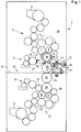
- a printing unit 1 comprises an upper inking unit 2 and a lower inking unit 21.
- a plurality of friction rollers 4 rub the ink supplied from an upper ink fountain 3.
- a dampening unit 5 is assigned to an upper first cylinder 19.
- a dampening applicator roller 6 and applicator rollers 7, 8 and 9 each apply dampening solution or ink to the surface of a form to be axially applied, such as a sleeve-like, tubular printing form which is mounted on the upper first cylinder 19.
- the rollers 6, 7, 8 and 9 can either take up a setting position or can be parked, ie they can be parked in a known manner from the surface of the upper first cylinder 19.
- An adjustable stop 14 is attached below a bearing housing 12 on the transmission side 32.
- the ratio of the contact pressure between the upper first cylinder 19 (e.g. a pressure cylinder) and an upper second cylinder 20 (e.g. a blanket cylinder) can be regulated.
- the support housing 12 on the transmission side 32 is connected to an actuating member 16 via a vertically extending coupling 15.
- the stretching of the actuating member 16 when the pressure cylinder 19 is switched off causes the support housing 12 to pivot counterclockwise about an axis 42 of the frame 32 on the transmission side.
- a support device 17 is also assigned to the support housing 12.
- the support device 17 is coupled to an actuation unit 18, which can be a pneumatic or hydraulic cylinder, an electric motor or a magnetic coil or another suitable organ.
- the actuation unit 18 moves the support device 17 laterally between a support position and a disengaged position. In Fig. 1, the support device 17 is shown in its disengaged position. As explained in more detail below, the support device 17 supports the support housing 12 in its support position during the parking of the printing cylinder 19.
- both sides of a web 44 are printed as it runs along a web path 43 through the gap between the upper second cylinder 20 (e.g. a blanket cylinder) and a lower second cylinder 30 (e.g. a blanket cylinder), both cylinders 20, 30 having a sleeve-shaped blanket attached to them.
- tubular printing formes are respectively mounted on the upper first cylinder 19 and the lower first cylinder 29. Additional printing units similar to the printing unit 1 shown in FIG. 1 can also be arranged in the web path 43.
- the lower inking unit 21 comprises a lower ink fountain 22, from which ink is supplied to the friction rollers 23 of the lower inking unit 21.
- paint is supplied onto the lower first cylinder 29.
- a dampening unit 24 is assigned to the lower inking unit 21 and, via the dampening application roller 25, supplies dampening solution to a sleeve-like, tubular printing form attached to the lower first cylinder 29.
- FIG. 2a shows a side view of the upper first cylinder 19 arranged between a transmission-side frame 32 and an operator-side frame 31.
- a counterweight mechanism 35 is also shown on the frame 32.
- FIG. 2b shows a plan view of the counterweight mechanism 35 and
- FIG. 2c shows the operator-side frame 31 in detail.
- the first cylinder 19 is in the printing mode and the counterweight mechanism 35 is not connected.
- An actuator 16.1 is attached to the operator-side frame 31, which has a coupling 15.1, which is detachably connected to the operator-side support housing 180.
- the operator-side support housing 180 in turn comprises a gate 182 which is pivotally attached to a carrier 184 and a gate actuation mechanism 186.
- the operator-side support housing 180 is rotatable about an axis 188. In the printing mode, the operator-side support housing 180 supports the cylinder 19.
- the support housing 12 is attached to the transmission-side frame 32 so as to be rotatable about the axis 42, as shown in FIG. 1.
- the actuators 16, 16.1 are coupled, the support housings 12, 180 are rotated about the axes 42, 188 via the couplings 15, 15.1 (viewed counterclockwise from the perspective of FIG. 1), and the upper first cylinder 19 becomes from the upper one second cylinder 20 turned off with an upward arcuate movement.
- the counterweight mechanism 35 can be actuated and the gate 182 can then be opened in order to enable the sleeve 33 to be installed or removed.
- the upper second cylinder 20 remains immobile during parking.
- the counterweight mechanism 35 shown in its unconnected position comprises an actuator 39, e.g. B. a pneumatic Cylinder, a toggle link 38 and a counterweight lever 37 with an arcuate part 370 next to a cylinder bearing 36.
- the counterweight lever 37 is pivotally mounted on a counterweight frame 380. In the non-connected position of the lever 37, its arcuate part 370 is not in contact with the cylinder bearing 36.
- FIG. 3a shows a side view of the upper first cylinder 19 arranged between the transmission-side frame 32 and the operator-side frame 31 and a counterweight mechanism 35.
- FIG. 3b shows a top view of the counterweight mechanism 35
- FIG. 3c shows the operator-side frame 31 in detail.
- the upper first cylinder 19 is in the non-pressure mode (i.e., turned off) and the counterweight mechanism 35 is connected.
- the upper first cylinder 19 is moved into its parking position by actuating members 16, 16. 1 located on the operator-side and gear-side frames 31, 32, respectively. Then, the counterweight mechanism 35 is operated, whereby the arcuate part 370 of the lever 37 is brought into contact with the cylinder bearing 36.
- a support device 17, which is slidably mounted on a sliding plate 34, is actuated and inserted into the gearbox-side support housing 12, the cylinder bearing 36 and the gearbox-side support housing 12 remaining immobile.
- the operator-side frame 31 has an opening 31.1.
- the bearing housing 13 on the operator-side frame 31 of the upper first cylinder 19 is released, which results in the removal of the sleeve 33 through the opening 31.1 within the operator-side frame 31 allows.
- the bearing housing 13 on the operator-side frame 31 can be released and thus in its position on the pin 190 of the upper first cylinder 19 on the operator-side frame 31 remain, as shown in Fig. 3c.
- the gate 182 is opened by a gate actuation device 186 and the sleeve 33 can be applied or removed through the opening 31.1.
- the cylinder 19 is supported by the support housing 12 and the counterweight mechanism 35.
- the support housing 12 is in turn held in position by the actuator 16 and the coupling 15.
- the support device 17 and the slide plate 34 protect the cylinder 19 from damage in the event of failure of the actuator 16 or the coupling 15.
- the actuator 39 in a manner as shown in Figs. 2b, 3b, i. H. protection against failure of the actuator 39 may also be provided by the actuator 39 being in a retracted state while the counterweight mechanism 35 is connected. Since the support device 17 supports the cylinder when the counterweight mechanism 35 is connected, the actuator 16 need not be designed to carry the full weight of the cylinder.
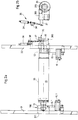
- Fig. 4 shows the transmission-side support housing 12 in detail.
- Upper first cylinder 19 and upper second cylinder 20 are in print mode. A print image is transferred from the upper first cylinder 19 to the upper second cylinder 20 and then to the surface of a web 44 that moves through the gap between the upper second cylinder 20 and the lower second cylinder 30.
- the application rollers 6, 7, 8 and 9 each transfer ink or dampening solution to the surface of the upper first cylinder 19.
- the bearing housing 12 is rotatably mounted about the axis 42 of the frame 32 on the transmission side.
- the support housing 12 is supported by a stop 14 which is adjustably mounted on the slide plate 34 of the frame 32 on the transmission side.
- the bearing housing 12 is connected to the actuator 16 via the coupling 15.
- the coupling 15 is connected to the support housing 12 so as to be rotatable about an axis 120.
- a control disk 40 is also attached, which has a beveled Surface area 41 of the wedge-shaped support device 17 cooperates.
- the support device 17 is moved into and out of contact with the control disk 40 by an actuating unit 18.
- the actuation units 16, 16.1, 18 and 39 can, for. B. pneumatic cylinders, electric motors with or without gears, magnetic coils, hydraulic working cylinders or other suitable organs for actuating the support device 17 or the coupling 15, 15.1, 38.
- FIG. 5 shows the support housing 12 in a parked position.
- the inking rollers 7, 8, 9 and the dampening roller 6 are set down from the surface of the upper first cylinder 19 using conventional means. Since the support housing 12 is rotated slightly about the axis 42 and thus leaves the stop 14, the upper first cylinder 19 does not come into contact with the cylinder 20 or the rollers 6-9.
- the wedge-shaped support device 17 is moved onto the slide plate 34. As explained above, the support device 17 is moved sideways by the operating unit 18. In order to reduce friction, an inclined part 41 of the support device 17 contacts the control disk 40, which is attached to the support housing 12 so as to be rotatable about the axis 120, which makes it easier to position or engage the support device 17 below the support housing 12.
- the upper first cylinder 19 After activation of the support device 17, the upper first cylinder 19 is held in position on the transmission-side frame 32, secured by the counterweight mechanism 35 located outside the transmission-side frame 32 and additionally by the support device 17, which is connected to the control disk 40 attached to the support housing 12 is in contact. If a sudden pressure drop occurs in an actuating member 16 while a sleeve is being removed, the support housing 12 is largely held in its parked position by the support device 17.
- the parking in the lower inking unit can, for. B. can be achieved in the manner disclosed in US 5,301,609.
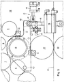
- FIG. 6 shows an embodiment of a parking mechanism 290 for the lower inking unit 21 shown in FIG. 1.
- the parking mechanism 290 is shown in a printing position or in an employed position (as opposed to the deactivated position).
- the lower first cylinder 29 is mounted on a carrier 260 and can be stopped with a downward movement about an axis 200 via a first piston 210 driven by an actuator 220.
- the lower second cylinder 30 is mounted on a carrier 230.
- the carrier 230 has a stop 240 and is mounted rotatably about an axis 250.
- piston 210 holds carrier 260 and lower first cylinder 29 in position.
- the carrier 230 and the lower second cylinder 30 are held in position by the stop 240 located on the carrier 260.
- the carrier 260 rotates the lower first cylinder 29 about the axis 200 and into the storage position. During this rotation, gravity causes the carrier 230 to rotate the lower second cylinder 30 clockwise until a stop 270 is in contact with a block 280. After the rotation of the carrier 230 is stopped by the block 280, the carrier 260 continues to rotate under the pressure exerted by the piston 210, the lower second cylinder 30 being separated from the upper second cylinder 20 and the lower first cylinder 29. As mentioned above, the upper first cylinder 19 is stopped by the upper second cylinder 20 with an upward movement, as shown in FIGS. 1-5. The upper second cylinder 20 remains immobile during parking.
- Fig. 1 If the lower first and second cylinders shown in Fig. 1 are each designed to receive sleeve-shaped blankets and printing forms, then these two cylinders can be supported during the application and removal of the sleeves in the manner described in US 5,237,920.
- an upper counterweight mechanism 300 and a lower counterweight mechanism 400 hold the lower second cylinder 30 and the lower first cylinder 29 in position, respectively, while the sleeves are being applied or removed.
- an actuator 310 moves a piston 320 outward, whereby a coupling 350 rotates a lever 330 clockwise about an axis 340 so that an arcuate portion of the lever 330 contacts the surface of the bearing 36 of the lower second Cylinder 30 comes into contact.
- an actuator 410 moves a piston 420 outward, whereby a coupling 450 rotates a lever 430 clockwise about an axis 440 so that an arcuate portion of the lever 430 contacts the surface of the bearing 36 of the lower first cylinder 29 comes into contact.
- the bearings of the respective cylinders on the operator-side frame 31 can be released and the respective sleeves can be attached or removed.
- One way in which the bearings of the upper first cylinder 19, the upper second cylinder 20, the lower first cylinder 29 and the lower second cylinder 30 can be released is described in detail in US Pat. No. 5,241,905.
- the present invention has been shown for a double-sided offset printing press in which the upper first cylinder 19 is turned off by an upward movement, the upper second cylinder 20 remains immobile, and the lower first 29 and second cylinder 30 be stopped by a downward movement.
- the present invention is not limited to such a configuration.
- the counterweight and lift mechanism illustrated in Figures 1, 2a, 2b, 3a, 3b, 4, and 5 could also be used in a printing press in which the lower first cylinder 29 would remain immobile during parking and the lower one second 30, upper second 20 and upper first cylinders 19 would all be shut down with an upward movement.
- the counterweight and lifting mechanism shown in Figures 1, 2a, 2b, 3a, 3b, 4 and 5 could also be used in a printing press in which the lower second cylinder 30 remains immobile during parking the upper second 20 and upper first cylinder 19 would be stopped with an upward movement and the lower first cylinder 29 with a downward movement. Ultimately, all four cylinders could be shut down with an upward movement.
- the present invention is also applicable to single-sided offset printing machines with a blanket cylinder, an impression cylinder and an impression cylinder.
- the present invention is in no way limited to use in offset printing machines.
- the invention is applicable to any processing machine that includes sleeved bodies.
- the counterweight and lifting mechanism according to the present invention could e.g. B. in connection with other image-bearing cylinders, such as engraved raster cylinders, gravure cylinders, letterpress cylinders, fexo printing cylinders or electronically illustrated cylinders.
Landscapes
- Engineering & Computer Science (AREA)
- Mechanical Engineering (AREA)
- Rotary Presses (AREA)
- Forklifts And Lifting Vehicles (AREA)
- Jib Cranes (AREA)
- Chain Conveyers (AREA)
- Coating With Molten Metal (AREA)
- Auxiliary Devices For And Details Of Packaging Control (AREA)
- Cage And Drive Apparatuses For Elevators (AREA)
- Liquid Crystal Substances (AREA)
- Vehicle Body Suspensions (AREA)
Applications Claiming Priority (2)
| Application Number | Priority Date | Filing Date | Title |
|---|---|---|---|
| US08/577,996 US5678485A (en) | 1995-12-22 | 1995-12-22 | Counterpoise and lift mechanism |
| US577996 | 1995-12-22 |
Publications (3)
| Publication Number | Publication Date |
|---|---|
| EP0782920A2 true EP0782920A2 (fr) | 1997-07-09 |
| EP0782920A3 EP0782920A3 (fr) | 1997-10-22 |
| EP0782920B1 EP0782920B1 (fr) | 1999-05-26 |
Family
ID=24311020
Family Applications (1)
| Application Number | Title | Priority Date | Filing Date |
|---|---|---|---|
| EP96116475A Expired - Lifetime EP0782920B1 (fr) | 1995-12-22 | 1996-10-15 | Contrepoids et mécanisme de levage |
Country Status (7)
| Country | Link |
|---|---|
| US (1) | US5678485A (fr) |
| EP (1) | EP0782920B1 (fr) |
| JP (1) | JP3863953B2 (fr) |
| CN (1) | CN1093468C (fr) |
| AT (1) | ATE180439T1 (fr) |
| CA (1) | CA2190400C (fr) |
| DE (2) | DE59601992D1 (fr) |
Families Citing this family (30)
| Publication number | Priority date | Publication date | Assignee | Title |
|---|---|---|---|---|
| DE19603500A1 (de) * | 1996-01-31 | 1997-08-07 | Polywest Kunststofftechnik | Hülse für eine Tiefdruckwalze, Verfahren zu ihrer Herstellung und Arbeitsverfahren der Vorrichtung zur Herstellung |
| FR2756214B1 (fr) * | 1996-11-28 | 1999-02-12 | Heidelberg Harris Sa | Dispositif de deplacement de cylindres d'un groupe d'impression recto-verso d'une machine rotative a imprimer |
| DE19816659B4 (de) * | 1997-05-26 | 2005-04-07 | Heidelberger Druckmaschinen Ag | Verfahren und Vorrichtung zum Schutz gegen das Eindringen von Fremdkörpern in einen Walzenspalt |
| DE19820159A1 (de) * | 1997-08-07 | 1999-02-11 | Heidelberger Druckmasch Ag | Stellvorrichtung für eine Druckmaschine |
| DE19740129C2 (de) * | 1997-09-12 | 2003-08-14 | Roland Man Druckmasch | Rotationsdruckmaschine mit stirnseitig freilegbaren Zylindern |
| FR2778599B1 (fr) * | 1998-05-13 | 2000-08-04 | Heidelberger Druckmasch Ag | Dispositif de deplacement des cylindres de groupes d'impression de machines rotatives a imprimer |
| DE29901697U1 (de) * | 1999-02-01 | 2000-07-13 | Heidelberger Druckmaschinen Ag, 69115 Heidelberg | Farbwerk in einer Druckmaschine |
| US6343547B1 (en) | 1999-11-12 | 2002-02-05 | Heidelberger Druckmaschinen Ag | Cantilevered cylinder counterpoise device and method |
| US6289805B1 (en) | 2000-02-08 | 2001-09-18 | Heidelberger Druckmaschinen Ag | Device and method for driving a printing cylinder |
| JP2002046251A (ja) * | 2000-06-26 | 2002-02-12 | Heidelberger Druckmas Ag | 偏心箱を使用して胴の胴抜きを行うための機構 |
| DE10261985A1 (de) * | 2002-09-21 | 2004-04-08 | Koenig & Bauer Ag | Vorrichtung zum Einstellen des Anpressdrucks einer verstellbar gelagerten Walze |
| NL1022048C2 (nl) * | 2002-12-02 | 2004-06-03 | Mps Holding B V | Drukmodule alsmede een drukmachine voorzien van een dergelijke drukmodule. |
| DE10305956B4 (de) * | 2003-02-12 | 2004-12-23 | Windmöller & Hölscher Kg | Verfahren zum Wechseln von Druckhülsen in einer Druckmaschine |
| US6877424B1 (en) * | 2004-03-11 | 2005-04-12 | Goss International Americas, Inc. | Counterpoise device and method for cantilevered printing press cylinders |
| DE202004015229U1 (de) * | 2004-09-30 | 2006-02-09 | Kark Ag | Vorrichtung mit mehreren Walzen |
| US7775159B2 (en) | 2005-03-30 | 2010-08-17 | Goss International Americas, Inc. | Cantilevered blanket cylinder lifting mechanism |
| WO2006104830A2 (fr) | 2005-03-30 | 2006-10-05 | Goss International Americas, Inc. | Presse a imprimer offset sur papier sans fin pourvue d'une lame plieuse articulee |
| JP4814309B2 (ja) * | 2005-03-30 | 2011-11-16 | ゴス インターナショナル アメリカス インコーポレイテッド | ブランケット胴胴抜き支持面を有する印刷ユニット |
| CN101208201B (zh) | 2005-03-30 | 2011-10-05 | 高斯国际美洲公司 | 具有自动装版的卷筒纸胶印印刷机 |
| JP4829291B2 (ja) * | 2005-04-11 | 2011-12-07 | ゴス インターナショナル アメリカス インコーポレイテッド | 単一モータ駆動を用いて自動プレーティングを可能にする印刷ユニット |
| US7617772B2 (en) * | 2005-05-13 | 2009-11-17 | Heidelberger Druckmaschinen Ag | Balancing system for balancing a printing drum and method for balancing the printing drum |
| US20060278105A1 (en) * | 2005-06-13 | 2006-12-14 | Chih-Chieh Hsiao | Positioning device for printing device of printing apparatus for paperboards for making paper boxes |
| CN100356957C (zh) * | 2005-11-17 | 2007-12-26 | 何明利 | 一种治疗乳腺增生的中药贴剂及其制备方法 |
| FR2895305B1 (fr) * | 2005-12-27 | 2009-04-17 | Goss Int Montataire Sa | Presse d'impression a engagement de bande ameliore et procede d'engagement de bande correspondant. |
| FR2895306B1 (fr) * | 2005-12-27 | 2008-04-04 | Goss Int Montataire Sa | Unite d'impression a amplitudes differentes de deplacement des cylindres porte-blanchet pour atteindre une configuration hors-pression et presse d'impression correspondante. |
| FR2895308B1 (fr) * | 2005-12-27 | 2009-07-03 | Goss Int Montataire Sa | Unite d'impression a configuration hors-pression de changement de blanchet tubulaire permettant le passage d'une bande de papier et presse d'impression correspondante. |
| FR2895307B1 (fr) * | 2005-12-27 | 2008-03-14 | Goss Int Montataire Sa | Unite d'impression a configuration hors-pression permettant de limiter les risques d'endommagement des cylindres par enroulement de la bande de papier, et presse d'impression correspondante. |
| FR2895309B1 (fr) * | 2005-12-27 | 2009-07-03 | Goss Int Montataire Sa | Unite d'impression presentant une configuration hors-pression d'arret et une configuration hors-pression de changement de blanchet et presse d'impression correspondante |
| JP6084439B2 (ja) * | 2012-11-09 | 2017-02-22 | 株式会社ミヤコシ | バリアブル印刷機 |
| CN104814945A (zh) * | 2015-05-14 | 2015-08-05 | 王兴民 | 一种远红外散结乳安贴 |
Family Cites Families (8)
| Publication number | Priority date | Publication date | Assignee | Title |
|---|---|---|---|---|
| US4458591A (en) * | 1982-09-30 | 1984-07-10 | Harris Graphics Corporation | Rotary printing press |
| DE4008501A1 (de) * | 1989-12-18 | 1991-06-20 | Windmoeller & Hoelscher | Druckmaschine mit presseurs mit austauschbaren huelsenfoermigen presseurmaenteln |
| DE4041497A1 (de) * | 1990-12-22 | 1992-06-25 | Roland Man Druckmasch | Lagerung fuer einen druckwerkzylinder |
| DE4124832C2 (de) * | 1991-07-26 | 1994-10-27 | Roland Man Druckmasch | Walzenschloß für eine Gummiwalze einer Druckmaschine |
| US5237920A (en) * | 1992-06-22 | 1993-08-24 | Heidelberg Harris Inc. | Apparatus for supporting a cylinder in a rotary printing unit |
| US5241905A (en) * | 1992-10-27 | 1993-09-07 | Heidelberg Harris Inc. | Printing unit with releasable bearing clamp |
| US5301609A (en) * | 1993-03-04 | 1994-04-12 | Heidelberg Harris Inc. | Printing unit with skew and throw-off mechanisms |
| DE4413807C1 (de) * | 1994-04-20 | 1995-09-14 | Windmoeller & Hoelscher | Vorrichtung zum Wechseln der Zylinder an einer Druckmaschine |
-
1995
- 1995-12-22 US US08/577,996 patent/US5678485A/en not_active Expired - Lifetime
-
1996
- 1996-10-15 DE DE59601992T patent/DE59601992D1/de not_active Expired - Lifetime
- 1996-10-15 EP EP96116475A patent/EP0782920B1/fr not_active Expired - Lifetime
- 1996-10-15 AT AT96116475T patent/ATE180439T1/de not_active IP Right Cessation
- 1996-10-22 DE DE19643568A patent/DE19643568A1/de not_active Ceased
- 1996-11-15 CA CA002190400A patent/CA2190400C/fr not_active Expired - Fee Related
- 1996-12-19 JP JP33967696A patent/JP3863953B2/ja not_active Expired - Fee Related
- 1996-12-20 CN CN96114181A patent/CN1093468C/zh not_active Expired - Fee Related
Also Published As
| Publication number | Publication date |
|---|---|
| JPH09183209A (ja) | 1997-07-15 |
| CA2190400C (fr) | 2000-01-25 |
| CA2190400A1 (fr) | 1997-06-23 |
| DE19643568A1 (de) | 1997-06-26 |
| CN1157213A (zh) | 1997-08-20 |
| DE59601992D1 (de) | 1999-07-01 |
| ATE180439T1 (de) | 1999-06-15 |
| HK1001124A1 (en) | 1998-05-29 |
| JP3863953B2 (ja) | 2006-12-27 |
| US5678485A (en) | 1997-10-21 |
| EP0782920B1 (fr) | 1999-05-26 |
| CN1093468C (zh) | 2002-10-30 |
| EP0782920A3 (fr) | 1997-10-22 |
Similar Documents
| Publication | Publication Date | Title |
|---|---|---|
| EP0782920B1 (fr) | Contrepoids et mécanisme de levage | |
| DE4332364C2 (de) | Druckwerk mit lösbarer Lagerbefestigung | |
| EP0956951B1 (fr) | Dispositif de déplacement de cylindres d'un groupe d'impression d'une machine rotative à imprimer | |
| EP0625423B1 (fr) | Unité d'impression avec dispositif d'inclinaison et d'arrêt | |
| DE4315909C2 (de) | Vorrichtung zum Abstützen von Druckzylindern in einer Rotationsdruckmaschine | |
| EP2285572B1 (fr) | Machine a imprimer a mecanismes d'encrage multiples | |
| DE19937796A1 (de) | Druckwerk | |
| DE4408026A1 (de) | Druckwerk für eine Mehrfarbenrollenrotationsdruckmaschine | |
| EP1167028A2 (fr) | Mechanisme d'enlèvement des rouleaux dans une machine d'impression rotative | |
| DE4406573B4 (de) | Druckwerk einer Rotationsdruckmaschine | |
| EP1673224A1 (fr) | Elements structurels mobiles dans une machine d'impression | |
| EP0509414A1 (fr) | Unité d'impression pour une presse rotative | |
| DE69501218T2 (de) | Rotationsmaschine | |
| EP1099549B1 (fr) | Dispositif et procédé pour l'étaiement d'un cylindre en porte-à-faux | |
| DE19743111C2 (de) | Vorrichtung und Verfahren zum Verschieben von zwei Türen einer Seitenwand eines Druckwerkes | |
| DE102006061452A1 (de) | Druckplattenkassette | |
| DE112009002489T5 (de) | Druckmaschine und Druckgruppe für formatvariablen Offset | |
| DE2025676A1 (de) | Farbwerkkassette | |
| EP1303405B1 (fr) | Groupe d'impression d'une machine offset rotative | |
| EP2057017B1 (fr) | Élément d'impression d'une machine d'héliogravure | |
| DE19753820A1 (de) | Vorrichtung zum gegenseitigen Anstellen von Druckwerkzylindern | |
| DE29905660U1 (de) | Druckmaschine mit einer Reinigungseinrichtung zur Reinigung zweier Druckmaschinenzylinder | |
| EP1732760B1 (fr) | Groupe d'impression de machine a imprimer, muni d'un rouleau presseur | |
| DE10221744A1 (de) | Druckwerk | |
| DE2851933A1 (de) | Druckerpresse mit niederhaltevorrichtung fuer oberes schwenkbares farbwerk einer widerdruckmaschine |
Legal Events
| Date | Code | Title | Description |
|---|---|---|---|
| PUAI | Public reference made under article 153(3) epc to a published international application that has entered the european phase |
Free format text: ORIGINAL CODE: 0009012 |
|
| 17P | Request for examination filed |
Effective date: 19961015 |
|
| AK | Designated contracting states |
Kind code of ref document: A2 Designated state(s): AT DE FR GB IT NL |
|
| PUAL | Search report despatched |
Free format text: ORIGINAL CODE: 0009013 |
|
| RHK1 | Main classification (correction) |
Ipc: B41F 27/10 |
|
| AK | Designated contracting states |
Kind code of ref document: A3 Designated state(s): AT DE FR GB IT NL |
|
| GRAG | Despatch of communication of intention to grant |
Free format text: ORIGINAL CODE: EPIDOS AGRA |
|
| GRAG | Despatch of communication of intention to grant |
Free format text: ORIGINAL CODE: EPIDOS AGRA |
|
| GRAH | Despatch of communication of intention to grant a patent |
Free format text: ORIGINAL CODE: EPIDOS IGRA |
|
| 17Q | First examination report despatched |
Effective date: 19981030 |
|
| GRAH | Despatch of communication of intention to grant a patent |
Free format text: ORIGINAL CODE: EPIDOS IGRA |
|
| GRAA | (expected) grant |
Free format text: ORIGINAL CODE: 0009210 |
|
| AK | Designated contracting states |
Kind code of ref document: B1 Designated state(s): AT DE FR GB IT NL |
|
| PG25 | Lapsed in a contracting state [announced via postgrant information from national office to epo] |
Ref country code: NL Free format text: LAPSE BECAUSE OF FAILURE TO SUBMIT A TRANSLATION OF THE DESCRIPTION OR TO PAY THE FEE WITHIN THE PRESCRIBED TIME-LIMIT Effective date: 19990526 |
|
| REF | Corresponds to: |
Ref document number: 180439 Country of ref document: AT Date of ref document: 19990615 Kind code of ref document: T |
|
| REF | Corresponds to: |
Ref document number: 59601992 Country of ref document: DE Date of ref document: 19990701 |
|
| GBT | Gb: translation of ep patent filed (gb section 77(6)(a)/1977) |
Effective date: 19990727 |
|
| ITF | It: translation for a ep patent filed | ||
| ET | Fr: translation filed | ||
| PG25 | Lapsed in a contracting state [announced via postgrant information from national office to epo] |
Ref country code: AT Free format text: LAPSE BECAUSE OF NON-PAYMENT OF DUE FEES Effective date: 19991015 |
|
| PLBE | No opposition filed within time limit |
Free format text: ORIGINAL CODE: 0009261 |
|
| STAA | Information on the status of an ep patent application or granted ep patent |
Free format text: STATUS: NO OPPOSITION FILED WITHIN TIME LIMIT |
|
| 26N | No opposition filed | ||
| REG | Reference to a national code |
Ref country code: GB Ref legal event code: IF02 |
|
| REG | Reference to a national code |
Ref country code: GB Ref legal event code: 732E |
|
| PG25 | Lapsed in a contracting state [announced via postgrant information from national office to epo] |
Ref country code: IT Free format text: LAPSE BECAUSE OF NON-PAYMENT OF DUE FEES Effective date: 20051015 |
|
| REG | Reference to a national code |
Ref country code: FR Ref legal event code: TP |
|
| PGFP | Annual fee paid to national office [announced via postgrant information from national office to epo] |
Ref country code: DE Payment date: 20101027 Year of fee payment: 15 |
|
| PGFP | Annual fee paid to national office [announced via postgrant information from national office to epo] |
Ref country code: GB Payment date: 20101025 Year of fee payment: 15 |
|
| PGFP | Annual fee paid to national office [announced via postgrant information from national office to epo] |
Ref country code: FR Payment date: 20111028 Year of fee payment: 16 |
|
| GBPC | Gb: european patent ceased through non-payment of renewal fee |
Effective date: 20111015 |
|
| PG25 | Lapsed in a contracting state [announced via postgrant information from national office to epo] |
Ref country code: GB Free format text: LAPSE BECAUSE OF NON-PAYMENT OF DUE FEES Effective date: 20111015 |
|
| REG | Reference to a national code |
Ref country code: FR Ref legal event code: ST Effective date: 20130628 |
|
| PG25 | Lapsed in a contracting state [announced via postgrant information from national office to epo] |
Ref country code: DE Free format text: LAPSE BECAUSE OF NON-PAYMENT OF DUE FEES Effective date: 20130501 |
|
| REG | Reference to a national code |
Ref country code: DE Ref legal event code: R119 Ref document number: 59601992 Country of ref document: DE Effective date: 20130501 |
|
| PG25 | Lapsed in a contracting state [announced via postgrant information from national office to epo] |
Ref country code: FR Free format text: LAPSE BECAUSE OF NON-PAYMENT OF DUE FEES Effective date: 20121031 |