EP0783978A2 - Trägerbahnlose Etikettenbahn, Verfahren zu deren Herstellung sowie Verfahren zur Reinigung und Verwendung eines Druckkopfes - Google Patents
Trägerbahnlose Etikettenbahn, Verfahren zu deren Herstellung sowie Verfahren zur Reinigung und Verwendung eines Druckkopfes Download PDFInfo
- Publication number
- EP0783978A2 EP0783978A2 EP97100066A EP97100066A EP0783978A2 EP 0783978 A2 EP0783978 A2 EP 0783978A2 EP 97100066 A EP97100066 A EP 97100066A EP 97100066 A EP97100066 A EP 97100066A EP 0783978 A2 EP0783978 A2 EP 0783978A2
- Authority
- EP
- European Patent Office
- Prior art keywords
- web
- print head
- label material
- printable
- cleaner
- Prior art date
- Legal status (The legal status is an assumption and is not a legal conclusion. Google has not performed a legal analysis and makes no representation as to the accuracy of the status listed.)
- Granted
Links
Images

Classifications
-
- B—PERFORMING OPERATIONS; TRANSPORTING
- B41—PRINTING; LINING MACHINES; TYPEWRITERS; STAMPS
- B41J—TYPEWRITERS; SELECTIVE PRINTING MECHANISMS, i.e. MECHANISMS PRINTING OTHERWISE THAN FROM A FORME; CORRECTION OF TYPOGRAPHICAL ERRORS
- B41J29/00—Details of, or accessories for, typewriters or selective printing mechanisms not otherwise provided for
- B41J29/17—Cleaning arrangements
-
- B—PERFORMING OPERATIONS; TRANSPORTING
- B65—CONVEYING; PACKING; STORING; HANDLING THIN OR FILAMENTARY MATERIAL
- B65H—HANDLING THIN OR FILAMENTARY MATERIAL, e.g. SHEETS, WEBS, CABLES
- B65H18/00—Winding webs
- B65H18/28—Wound package of webs
-
- G—PHYSICS
- G09—EDUCATION; CRYPTOGRAPHY; DISPLAY; ADVERTISING; SEALS
- G09F—DISPLAYING; ADVERTISING; SIGNS; LABELS OR NAME-PLATES; SEALS
- G09F3/00—Labels, tag tickets, or similar identification or indication means; Seals; Postage or like stamps
- G09F3/08—Fastening or securing by means not forming part of the material of the label itself
- G09F3/10—Fastening or securing by means not forming part of the material of the label itself by an adhesive layer
Definitions
- This invention relates to the art of linerless labels, methods of making same and to method of cleaning and using a thermal print head.
- thermal print heads can be cleaned using special cleaning strips which are advanced between and in pressure contact with the print head and the platen.
- the invention relates to an improved web capable of cleaning the print head and on which printing can subsequently be done using the cleaned print head.
- a cleaner is located downstream of a printable portion.
- the cleaner and the printable portion use a non-piece web for both the cleaner portion and the printable portion.
- a web including a marginal end portion having a cleaner for a thermal print head, and a printable portion connected to the marginal end portion for receiving thermally printed data.
- linerless printable pressure sensitive label material is roughened at the marginal end portion and this roughening cleans the print head before the remainder of the web is printed.
- the web to be printed on has a leading section referred to as a cleaner comprised of a section of increased frictional resistance over the friction offered by the silicone coated web itself.
- a specific embodiment of the invention includes a web of linerless pressure sensitive label material wound into a roll.
- the web terminates at an outer free end.
- a marginal end portion is provided by a outer protective wrap.
- the marginal end portion includes a partial wrap adjacent the outer wrap which is roughened by numerous lateral lines of perforation cuts. This roughening cleans the thermal print head. The remainder of the web can thus be printed upon using the cleaned thermal print head.
- the cleaner is comprised of a series of embossments, and in yet another embodiment the cleaner is comprised of a strained section caused by stressing the web, as by causing that section to undergo a sharp change in direction.
- the invention also includes a method of cleaning a thermal print head and using the thermal print head to print in cooperation with a platen to print on a web.
- the method comprises providing a web having a cleaner and a printable area, threading the web between the print head and the platen so that the printable area is upstream of the cleaner, advancing the web to bring the cleaner into cooperation with the print head to clean the print head, and further advancing the web and printing on the printable area only after the print head has been cleaned by the cleaner.
- the cleaner is preferably disposed between a protective outer wrap of the web and a printable area.
- the method preferably includes separating the outer wrap from the remainder of the web.
- the laterally extending perforation cuts are comprised of elongated cuts separated by intervening lands, wherein the elongate cuts and lands of alternate lines of perforation are staggered so that the lands of one line of perforation cuts are longitudinally aligned with elongate cuts of the adjacent lines of perforation cuts.
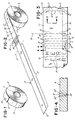
- FIGURE 1 With reference to FIGURE 1, there is shown a web 10 which has been wound into a roll R.
- the roll R is shown to have a core 11.
- the web 10 terminates at an outer terminal free end 12.
- the web 10 on the roll R has an outer protective wrap 13.
- the outer wrap 13 is shown to be free of any marks or perforation cuts.
- the outer wrap 13 is protective in that it keeps the remainder of the web 10 clean.
- the outer wrap 13 is shown to terminate at a line indicated at 15 which marks the beginning of the adjacent wrap.
- the length of the outer wrap 13 is, of course, dependent upon the diameter of the roll R.
- the web 10 also has a tear line 16 extending laterally across the web 10.
- There are printed instructions 14 such as "TEAR HERE" printed adjacent the tear line 16 so that the user will readily know where to tear off the outer wrap 13 plus preferably a little bit more.
- a cleaner C is provided by a plurality of closely longitudinally spaced lateral lines of perforation cuts 17 in the web 10.
- the cuts 17 comprise a cleaner C which is upstream of the outer wrap 13.
- the first or leading label L1 capable of being printed starts at line 18'.
- the second and subsequent labels are indicated at L2.
- FIGURE 3 shows a portion of the adjacent wrap in greater detail. It is seen that the perforation cuts 17 are provided by knife cuts 18 spaced apart by lands 19. The perforation cuts 17 are made along closely spaced parallel lines extending laterally across the web 10.
- the labels L1 and L2 are defined by perforation cuts 20 extending laterally across the web 10 at equally longitudinally spaced intervals.
- the labels L1 nd L2 are considered to be connected at the perforation cuts 20.
- the labels L1 and L2 are considered to be upstream of the cleaner C.
- FIGURE 4 illustrates a perforation cut 18.
- the material forming the web has been cammed apart, and indeed, the adjacent material 20' is compressed and there is some protrusion or bunching up of the material as indicated at 20".
- This provides localized hardness of the web material adjacent the knife cut 18, and constitutes increased friction and surface roughness. This results in cleaning action against the print head 27 as the web 20 moves relative to the print head 27.
- the web 10 is shown to be comprised of a web of paper 21 having a thermal coating 22.
- a barrier coating 23 on the thermal coating 22 and there is a release coating 24 comprised of silicone on the barrier coating 23.
- a coating of pressure sensitive adhesive 25 on the underside of the paper web 12.
- FIGURE 6 shows a thermal printer 26 having a thermal print head with a laterally extending line of printing elements cooperable with a platen 28 in the form of a roll.
- the platen 28 is shown to be driven by an electric motor 29 suitably coupled as indicated at 30.
- the roughening of the surface of the web by multiple lines of perforation cuts 17 is a simple and effective way to clean the print head.
- the outer wrap 13 is unwound to beyond the tear line 16.
- the web 10 is torn along the tear line 16 so that the outer wrap and preferably a little bit more of the web 10 are removed.
- the free end of the web 10 now exists along the line 16 as shown in FIGURE 6.
- the web 10 is threaded between the print head 27 and the platen 28, and the platen 28 is rotated to advance the cleaner C in contact with the print head 27.
- Such contact of the cleaner C with the print head 27 cleans the print head so that when the leading label L1 and subsequent labels L2 are printed, streaks on the printable surface of the web 10 will be avoided.
- adjacent lines of perforation cuts 17 are staggered so that the lands of one line of perforation cuts 17 are longitudinally aligned with the lands 18 of the adjacent line or lines of perforation cuts 17.
- longitudinal phantom line PL which shows the staggered knife cuts 18 and 32.
- the lines of perforation cuts 20 which form the labels L1 and L2 are also staggered in that the lands 31 of adjacent lines 20 of perforation cuts are offset in an alternating pattern.
- FIGURE 3 shows lands 31 of one line 20 longitudinally aligned with perforation cuts 32 of the adjacent line 20.
- the lines of perforation cuts 17 help to maintain the print head in the clean state so that build up of dirt, debris and the line do not become a problem.
- FIGURES 7 and 8 is the same as the embodiment of FIGURES 1 through 6, except that the surface roughness or increased friction is provided by embossments 40 along longitudinally spaced laterally extending lines, as shown.
- the embossments 40 are shown to be staggered or offset, one line to the other, so that all portions of the print head 27 will be cleaned.
- FIGURE 9 is the same as the embodiment of FIGURES 1 through 6, except that cleaner C is formed by causing the material indicated at C to undergo a sharp change in direction, as by passing it at a sharp angle about a turning bar, thereby stressing the web 20 and causing the resultant strain to impart a roughness or resultant strain to enhance surface friction of the web 20 so as to render it capable of cleaning a print head 27 during relative movement of the web 20 in contact with the print head 27.
Landscapes
- Physics & Mathematics (AREA)
- General Physics & Mathematics (AREA)
- Engineering & Computer Science (AREA)
- Theoretical Computer Science (AREA)
- Accessory Devices And Overall Control Thereof (AREA)
- Electronic Switches (AREA)
- Impression-Transfer Materials And Handling Thereof (AREA)
Applications Claiming Priority (2)
| Application Number | Priority Date | Filing Date | Title |
|---|---|---|---|
| US583251 | 1996-01-05 | ||
| US08/583,251 US5926197A (en) | 1996-01-05 | 1996-01-05 | Linerless label web, method of making same and method of cleaning and using a print head |
Publications (3)
| Publication Number | Publication Date |
|---|---|
| EP0783978A2 true EP0783978A2 (de) | 1997-07-16 |
| EP0783978A3 EP0783978A3 (de) | 1999-04-07 |
| EP0783978B1 EP0783978B1 (de) | 2003-07-23 |
Family
ID=24332324
Family Applications (1)
| Application Number | Title | Priority Date | Filing Date |
|---|---|---|---|
| EP97100066A Expired - Lifetime EP0783978B1 (de) | 1996-01-05 | 1997-01-03 | Trägerbahnlose Etikettenbahn, Verfahren zu deren Herstellung sowie Verfahren zur Reinigung und Verwendung eines Druckkopfes |
Country Status (4)
| Country | Link |
|---|---|
| US (1) | US5926197A (de) |
| EP (1) | EP0783978B1 (de) |
| CA (1) | CA2194187C (de) |
| DE (1) | DE69723591T2 (de) |
Cited By (4)
| Publication number | Priority date | Publication date | Assignee | Title |
|---|---|---|---|---|
| EP0876909A1 (de) * | 1997-05-05 | 1998-11-11 | Monarch Marking Systems, INC. | Trennfolienfreie Etiketten und Herstellungsverfahren |
| GB2324258B (en) * | 1997-04-17 | 1999-11-03 | Ernest William Fitton | An attachment means |
| WO1999056963A1 (en) * | 1998-05-01 | 1999-11-11 | Moore U.S.A., Inc. | Printer cleaning card integrated into web of printable labels |
| US10668716B2 (en) | 2017-02-07 | 2020-06-02 | Assa Abloy Ab | Transfer film having a roller cleaning section |
Families Citing this family (14)
| Publication number | Priority date | Publication date | Assignee | Title |
|---|---|---|---|---|
| JP2001047648A (ja) * | 1999-08-11 | 2001-02-20 | Fuji Photo Film Co Ltd | サーマルプリンタ及びクリーニング方法及び記録紙ロール |
| JP2003072054A (ja) * | 2001-09-04 | 2003-03-12 | Seiko Epson Corp | インク式記録装置、及び、そのクリーニング制御方法 |
| US7274384B2 (en) * | 2002-05-23 | 2007-09-25 | Intermec Ip Corp. | Self cleaning thermal media |
| US7089859B2 (en) * | 2003-09-17 | 2006-08-15 | Rx Label Corp. | Document with integrated coating |
| US6908240B1 (en) * | 2003-12-16 | 2005-06-21 | International Imaging Materials, Inc | Thermal printing and cleaning assembly |
| US7588811B2 (en) * | 2004-03-19 | 2009-09-15 | Ncr Corporation | Columnar adhesive label roll |
| US7820264B2 (en) * | 2004-12-16 | 2010-10-26 | Ncr Corporation | Idle registered label roll |
| US8445104B2 (en) * | 2006-05-18 | 2013-05-21 | MAXStick Products Ltd. | Thermally printable adhesive label |
| WO2008147925A2 (en) * | 2007-05-22 | 2008-12-04 | Futurelogic, Inc. | Methods and apparatus for produce labeling |
| JP2010070837A (ja) * | 2008-09-22 | 2010-04-02 | Fujifilm Corp | フィルムロールおよび成膜装置のクリーニング方法 |
| JP2016029615A (ja) * | 2014-07-25 | 2016-03-03 | Jnc株式会社 | 電池セパレータ用微多孔フィルム捲回物とその製造方法 |
| US9972222B2 (en) * | 2015-01-28 | 2018-05-15 | Odds, Llc | Label roll with a blank leader and method of manufacturing |
| US10176731B2 (en) | 2016-08-19 | 2019-01-08 | Iconex Llc | Adhesive label and roll |
| CN114803608B (zh) * | 2022-05-05 | 2023-10-27 | 深圳市鑫洲芯微电子有限公司 | 一款芯片编带时的自动卷盘设备 |
Citations (2)
| Publication number | Priority date | Publication date | Assignee | Title |
|---|---|---|---|---|
| US4899947A (en) | 1986-07-15 | 1990-02-13 | Monarch Marking Systems, Inc. | Reel for mounting record member roll |
| US5086987A (en) | 1989-04-24 | 1992-02-11 | Monarch Marking Systems, Inc. | Method of making rolls of record members |
Family Cites Families (12)
| Publication number | Priority date | Publication date | Assignee | Title |
|---|---|---|---|---|
| US4369456A (en) * | 1981-08-26 | 1983-01-18 | Pitney Bowes Inc. | Cleaning device for writing heads used in ink jet recorders and printers |
| JPS6049985A (ja) * | 1983-08-30 | 1985-03-19 | Ricoh Co Ltd | サ−マルヘッドのクリ−ニング方法 |
| US4590497A (en) * | 1984-11-05 | 1986-05-20 | Ricoh Electronics, Inc. | Heat insulated thermosensitive paper |
| JPS62297172A (ja) * | 1986-06-17 | 1987-12-24 | Matsushita Electric Ind Co Ltd | 放電記録シ−ト |
| JPS63114691A (ja) * | 1986-11-01 | 1988-05-19 | Seiki Kogyo Kk | 感熱孔版印刷用原紙 |
| US4851383A (en) * | 1987-06-08 | 1989-07-25 | Ricoh Electronics, Inc. | Non-laminate thermosensitive, pressure sensitive label and method of manufacture |
| JPS63303779A (ja) * | 1987-10-23 | 1988-12-12 | Dainippon Printing Co Ltd | 感熱転写プリンタ |
| JPH0298476A (ja) * | 1988-10-05 | 1990-04-10 | Nippon Seimitsu Kogyo Kk | サーマルヘッドのクリーニング方法 |
| JPH03111076A (ja) * | 1989-09-25 | 1991-05-10 | Daikoku Denki Kk | パチンコホール用集中管理装置 |
| JPH04173289A (ja) * | 1990-11-06 | 1992-06-19 | Ricoh Co Ltd | サーモクロミックフイルム記録帯 |
| WO1993021020A1 (en) * | 1992-04-09 | 1993-10-28 | Intermec Corporation | Method and apparatus for cleaning a thermal printhead |
| US5292713A (en) * | 1992-07-15 | 1994-03-08 | Stenzel Herbert J | Linerless thermal and thermal transfer labels |
-
1996
- 1996-01-05 US US08/583,251 patent/US5926197A/en not_active Expired - Fee Related
- 1996-12-30 CA CA002194187A patent/CA2194187C/en not_active Expired - Fee Related
-
1997
- 1997-01-03 DE DE69723591T patent/DE69723591T2/de not_active Expired - Fee Related
- 1997-01-03 EP EP97100066A patent/EP0783978B1/de not_active Expired - Lifetime
Patent Citations (2)
| Publication number | Priority date | Publication date | Assignee | Title |
|---|---|---|---|---|
| US4899947A (en) | 1986-07-15 | 1990-02-13 | Monarch Marking Systems, Inc. | Reel for mounting record member roll |
| US5086987A (en) | 1989-04-24 | 1992-02-11 | Monarch Marking Systems, Inc. | Method of making rolls of record members |
Cited By (5)
| Publication number | Priority date | Publication date | Assignee | Title |
|---|---|---|---|---|
| GB2324258B (en) * | 1997-04-17 | 1999-11-03 | Ernest William Fitton | An attachment means |
| EP0876909A1 (de) * | 1997-05-05 | 1998-11-11 | Monarch Marking Systems, INC. | Trennfolienfreie Etiketten und Herstellungsverfahren |
| WO1999056963A1 (en) * | 1998-05-01 | 1999-11-11 | Moore U.S.A., Inc. | Printer cleaning card integrated into web of printable labels |
| US6129019A (en) * | 1998-05-01 | 2000-10-10 | Moore U.S.A., Inc. | Printer cleaning card integrated into web of printable labels |
| US10668716B2 (en) | 2017-02-07 | 2020-06-02 | Assa Abloy Ab | Transfer film having a roller cleaning section |
Also Published As
| Publication number | Publication date |
|---|---|
| CA2194187A1 (en) | 1997-07-06 |
| DE69723591D1 (de) | 2003-08-28 |
| EP0783978B1 (de) | 2003-07-23 |
| EP0783978A3 (de) | 1999-04-07 |
| CA2194187C (en) | 2008-05-06 |
| DE69723591T2 (de) | 2004-04-15 |
| US5926197A (en) | 1999-07-20 |
Similar Documents
| Publication | Publication Date | Title |
|---|---|---|
| US5926197A (en) | Linerless label web, method of making same and method of cleaning and using a print head | |
| CA2213140C (en) | Method and apparatus for selectively dispensing liner-type and linerless-type labels, and a prepared linerless-type web and method of making and using same | |
| US2095437A (en) | Price marking tag and method of making the same | |
| US4905337A (en) | Lint remover | |
| US7588811B2 (en) | Columnar adhesive label roll | |
| US7893839B2 (en) | Deactivatable RFID labels and tags and methods of making same | |
| US3706626A (en) | Pressure sensitive labels | |
| WO2000023535A1 (en) | Adhesive roller construction | |
| US5622113A (en) | Gripping surface for cutting cylinders in a folding machine | |
| AU2001268893A1 (en) | Unit for the continuous production of printed textile strips, in particular printed label strips | |
| CA2246598C (en) | Apparatus for printing labels and a self-releasing print roller therefor | |
| US6139932A (en) | Linerless label web roll | |
| JP2002284131A (ja) | 台紙なしラベルプリンタ | |
| US5824379A (en) | Composite label web | |
| US20150015654A1 (en) | Rollers for a printer and a printer equipped with said rollers | |
| EP1053289B2 (de) | Selbstklebebonrolle | |
| JPH11513807A (ja) | マーカースリーブアセンブリ | |
| US6210054B1 (en) | Method for applying printer registration marks to linerless label stock | |
| US5139847A (en) | Continuous tags such as demand tags and method of making same | |
| US5106123A (en) | Roll of record members | |
| US5086987A (en) | Method of making rolls of record members | |
| JP4545283B2 (ja) | 剥離紙付きラベル | |
| GB2225766A (en) | Self-adhesive label strips | |
| JP2005316172A (ja) | 部分粘着ラベル | |
| GB2255029A (en) | Lateral tear tape. |
Legal Events
| Date | Code | Title | Description |
|---|---|---|---|
| PUAI | Public reference made under article 153(3) epc to a published international application that has entered the european phase |
Free format text: ORIGINAL CODE: 0009012 |
|
| AK | Designated contracting states |
Kind code of ref document: A2 Designated state(s): DE FR GB NL |
|
| 17P | Request for examination filed |
Effective date: 19971114 |
|
| PUAL | Search report despatched |
Free format text: ORIGINAL CODE: 0009013 |
|
| AK | Designated contracting states |
Kind code of ref document: A3 Designated state(s): DE FR GB NL |
|
| 17Q | First examination report despatched |
Effective date: 20000830 |
|
| GRAH | Despatch of communication of intention to grant a patent |
Free format text: ORIGINAL CODE: EPIDOS IGRA |
|
| GRAH | Despatch of communication of intention to grant a patent |
Free format text: ORIGINAL CODE: EPIDOS IGRA |
|
| GRAA | (expected) grant |
Free format text: ORIGINAL CODE: 0009210 |
|
| RAP1 | Party data changed (applicant data changed or rights of an application transferred) |
Owner name: PAXAR AMERICAS, INC. |
|
| AK | Designated contracting states |
Designated state(s): DE FR GB NL |
|
| REG | Reference to a national code |
Ref country code: GB Ref legal event code: FG4D |
|
| REF | Corresponds to: |
Ref document number: 69723591 Country of ref document: DE Date of ref document: 20030828 Kind code of ref document: P |
|
| ET | Fr: translation filed | ||
| PLBE | No opposition filed within time limit |
Free format text: ORIGINAL CODE: 0009261 |
|
| STAA | Information on the status of an ep patent application or granted ep patent |
Free format text: STATUS: NO OPPOSITION FILED WITHIN TIME LIMIT |
|
| 26N | No opposition filed |
Effective date: 20040426 |
|
| PGFP | Annual fee paid to national office [announced via postgrant information from national office to epo] |
Ref country code: GB Payment date: 20071218 Year of fee payment: 12 Ref country code: FR Payment date: 20071210 Year of fee payment: 12 |
|
| PGFP | Annual fee paid to national office [announced via postgrant information from national office to epo] |
Ref country code: NL Payment date: 20071219 Year of fee payment: 12 Ref country code: DE Payment date: 20071213 Year of fee payment: 12 |
|
| GBPC | Gb: european patent ceased through non-payment of renewal fee |
Effective date: 20090103 |
|
| NLV4 | Nl: lapsed or anulled due to non-payment of the annual fee |
Effective date: 20090801 |
|
| PG25 | Lapsed in a contracting state [announced via postgrant information from national office to epo] |
Ref country code: DE Free format text: LAPSE BECAUSE OF NON-PAYMENT OF DUE FEES Effective date: 20090801 |
|
| REG | Reference to a national code |
Ref country code: FR Ref legal event code: ST Effective date: 20091030 |
|
| PG25 | Lapsed in a contracting state [announced via postgrant information from national office to epo] |
Ref country code: NL Free format text: LAPSE BECAUSE OF NON-PAYMENT OF DUE FEES Effective date: 20090801 Ref country code: GB Free format text: LAPSE BECAUSE OF NON-PAYMENT OF DUE FEES Effective date: 20090103 |
|
| PG25 | Lapsed in a contracting state [announced via postgrant information from national office to epo] |
Ref country code: FR Free format text: LAPSE BECAUSE OF NON-PAYMENT OF DUE FEES Effective date: 20090202 |