EP0784231B1 - Gerät und Verfahren zur Handhabung von Filmbögenträgern - Google Patents
Gerät und Verfahren zur Handhabung von Filmbögenträgern Download PDFInfo
- Publication number
- EP0784231B1 EP0784231B1 EP97100244A EP97100244A EP0784231B1 EP 0784231 B1 EP0784231 B1 EP 0784231B1 EP 97100244 A EP97100244 A EP 97100244A EP 97100244 A EP97100244 A EP 97100244A EP 0784231 B1 EP0784231 B1 EP 0784231B1
- Authority
- EP
- European Patent Office
- Prior art keywords
- sheet holder
- film
- film sheet
- take
- holder
- Prior art date
- Legal status (The legal status is an assumption and is not a legal conclusion. Google has not performed a legal analysis and makes no representation as to the accuracy of the status listed.)
- Expired - Lifetime
Links
Images


Classifications
-
- G—PHYSICS
- G03—PHOTOGRAPHY; CINEMATOGRAPHY; ANALOGOUS TECHNIQUES USING WAVES OTHER THAN OPTICAL WAVES; ELECTROGRAPHY; HOLOGRAPHY
- G03D—APPARATUS FOR PROCESSING EXPOSED PHOTOGRAPHIC MATERIALS; ACCESSORIES THEREFOR
- G03D15/00—Apparatus for treating processed material
- G03D15/001—Counting; Classifying; Marking
- G03D15/005—Order systems, e.g. printsorter
-
- G—PHYSICS
- G03—PHOTOGRAPHY; CINEMATOGRAPHY; ANALOGOUS TECHNIQUES USING WAVES OTHER THAN OPTICAL WAVES; ELECTROGRAPHY; HOLOGRAPHY
- G03D—APPARATUS FOR PROCESSING EXPOSED PHOTOGRAPHIC MATERIALS; ACCESSORIES THEREFOR
- G03D15/00—Apparatus for treating processed material
- G03D15/10—Mounting, e.g. of processed material in a frame
Definitions
- the present invention relates to an apparatus and method for taking up a film sheet holder in which photographic film strips cut for one order amount are stored.
- a photographic film after developing and printing processes (to be referred to just as 'film' when appropriate hereinafter) is cut into pieces each containing e.g. four or six frames. Then, these film pieces corresponding to one consumer order amount are inserted into individual pockets (rows) of a foldable film sheet holder to be stored therein. After this, the holder is folded and inserted into a bag together with corresponding prints to be returned to the consumer.
- 'one order amount' used herein is understood to refer to the amount of film housed within one film patrone or cartridge.
- the apparatus of reference 1 does not effect the detection of the film sheet holder.
- reference 2 discloses, in its accompanying Fig. 11, an optical sensor unit including a light transmitter 188 and a light receiver 189, but this sensor unit is used only for forming a loop of the film sheet holder 26a. Accordingly, with these conventional apparatuses, the subsequent operations including transporting, taking up and discharging of the film sheet holder cannot be effected properly. In this respect, there has been room for improvement. Moreover, in the case of the apparatus of reference 2, the holder transporting direction is not changed before and after the holder folding operation, thus tending to invite enlargement of the entire apparatus.
- references 1 and 2 both are complicated in construction and large in physical size. Hence, in this respect too, there has been need for improvement.
- no detection is made for the presence or absence of a film held in the film sheet holder.
- one object of the present invention is to improve the efficiency of the operation involving the taking up (or folding) of the film sheet holder, by selectively not taking up any holders that need not be taken up.
- Another object of the present invention is to provide a film sheet holder handling (taking up or folding) apparatus which is simple in construction and compact in the physical size.
- a film sheet holder handling apparatus for taking up a film sheet holder in which photographic film strips cut for one order amount are stored, comprises:
- the film detecting means detects presence/absence of the film. Based on this detection, it is possible to determine in advance whether the transported film sheet holder is to be folded or not. Accordingly, the series of operations relating to the film sheet holder may be effected appropriately.
- the film sheet holder handing apparatus further comprises:
- the apparatus takes up not all the transported sheet holders but only one or those holders storing the film therein. And, the former holders which need not be taken up are just discharged along the transport passage. That is, since those holders which do not require such subsequent operations as sorting and verifying operations are discharged without being taken up, as a result, the entire operational efficiency is improved.
- the film sheet holder handling apparatus further comprises:
- the sheet detecting means detects arrival of a film sheet holder.
- the film detecting means effects detection of presence/absence of the film. That is, the film sheet holder often has a printed surface. And, it is preferred, with respect to detection precision, to effect the detection at a position other than such printed surface portion. With the above, the presence/absence detection of the film may be effected more reliably.
- the film detecting means includes a plurality of sensors arranged along a width of the film sheet holder being transported, and the film detecting means effects the detection in the first row of the film sheet holder.
- the film presence/absence detection may be effected in a reliable manner. Further, as the film presence/absence detection is made at the first row of the holder which is the leading end in the transporting direction thereof, it is possible to determine whether to take up the film sheet holder or not at the early timing. This too may improve the operational efficiency.
- the take-up means includes a pair of take-up bars arranged eccentrically relative to a common revolution axis, so that a leading end of the film sheet holder is inserted between the pair of take-up bars and the first row of the film sheet holder is taken up in association with concentric revolution of the take-up bars for pushing the first row of the film sheet holder.
- the film sheet holder may be taken up by the simple action of the concentric revolution of the pair of take-up bars.
- This construction is more simple than the conventional construction, so that the entire apparatus may be formed compact.
- said each take-up bar includes anti-slip means formed of a rubber element at a portion of the bar contacting the film sheet holder.
- the take-up operation may be effected reliably without slippage of the holder during this operation.
- the pair of take-up bars selectively assume a first posture for allowing insertion therebetween of the leading end of the film sheet holder and a second posture for allowing discharge of the taken-up film sheet holder from the take-up bars.
- the take-up bars assume the first posture in which the bars are disposed one above the other across the transport passage.
- the take-up bars assume the second posture for orienting the film face parallel with the transport passage, so that the subsequent handling of the film sheet holder may be facilitated.
- the film sheet holder handling apparatus further comprises:
- the first discharging means since the first discharging means is located away from the operational region of the take-up means during its take-up operation, the first discharging means does not interfere with the take-up operation, so that the take-up operation may take place in a reliable manner.
- the further feature of the push-out bar pushing out the holder after completion of the take-up operation away from the take-up means in the direction normal to the holder transporting direction may contribute further compactness of the entire apparatus.
- a method of handling a film sheet holder is provided, as defined in claim 9.
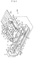
- Fig. 1 is a perspective view showing principal portions of a negative sheet holder handling apparatus 100 as one preferred embodiment of the film sheet holder handling apparatus relating to the present invention.
- a transporting unit 1 effects transportation of a negative sheet holder 4 along a direction denoted with an arrow A in Fig. 1.
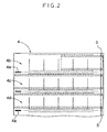
- the negative sheet holder 4 as one example of film sheet holder, has a configuration as shown in Fig. 2, in which a developed negative film 5 is cut into a plurality of film strips including 4 to 6 frames (six frames in this figure), and these film strips are sorted along the longitudinal direction of the film 5 for their storage in the holder 4.
- the negative sheet holder 4 includes a plurality of independent pocket rows 4b, 4c 4d..., with a negative sheet mark 4a being provided between adjacent rows.
- the transporting unit 1 the negative sheet holder 4 is transported with its first row 4 being at the leading end.
- a take-up unit 2 is provided for taking up the transported negative sheet holder 4 by each row thereof.
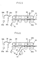
- a discharging unit 3 is provided for discharging the taken-up holder 4 onto a receiver plate 44, which is shown in Fig. 4.
- the transporting unit 1 includes a pair of right and left drive roller groups 10 disposed side by side across a transporting direction for together pinching the sheet holder 4 and transporting this holder 4 (in cooperation with a driven roller group 11 to be described later). Since the constructions of the drive roller groups (also the driven roller groups described later) on the two sides are identical to each other, only one group on one side will be described next.
- the drive roller group 10 include four drive rollers 10a, 10b, 10c and 10d, about which an endless belt 12 is entrained, so that the rollers are driven via the belt 12 by e.g. an unillustrated motor. Further, these rollers 10 are rotatably mounted to a mount plate 13 having an 'L'-shaped cross section. Under each drive roller group 10, there is disposed the cooperating driven roller group 11, which includes four driven rollers 11a, 11b, 11c and 11d in correspondence with the four drive rollers 10a, 10b, 10c and 10d.
- a discharging guide 14 is provided integrally therewith, with the driven roller 11c and the discharging guide 14 being pivotable about a pivot axis 14a.
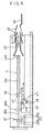
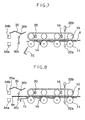
- the driven roller 11c and the guide 14 are located at a position for guiding the negative sheet holder 4 to the take-up unit 2, as illustrated in Fig. 3.
- the discharging guide 14 is pivoted counter-clockwise, whereby the negative sheet holder 4 is allowed to be discharged off the transport passage.
- a guide unit 15 is supported to be pivotable about a pivot shaft 15a. Normally, this guide unit 15 is located at a position retracted from the transport passage as shown in Fig. 3.
- the guide unit 15 is pivotally driven clockwise to a position facing the transport passage.
- a press roller 16 At a center between the drive roller groups 10 disposed side by side, there is provided a press roller 16.
- This press roller 16 when the discharging guide 14 is activated, discharges the negative sheet holder 4 away from the transport passage.
- the press roller 16 is rotatably supported at a leading end of a mount plate 17, which in turn is supported to be pivotable about a pivot shaft 18.
- this press roller 16 is supported by the pivot shaft 18 with a spacing from the transport passage corresponding to the thickness of the negative sheet holder 4.
- the press roller 16 may be urged by means of e.g. an unillustrated spring downwards from the transport passage.
- detecting switches 19 for detecting presence/absence of the negative sheet holder 4 and further detecting switches 20 for detecting the leading end of the negative sheet holder 4 are attached to respective side plates 21.
- these switches 19, 20 are comprised of limit switches.
- these switches may be comprised of optical sensors.
- these switches 19, 20 may be respectively provided on one side plate 21 alone.
- the mount plate 13 and the mount plate 17 respectively define slots 13a, 17a.
- These negative sensors 22 are provided for detecting presence/absence of the negative film 5 within the first pocket row 4b of the negative sheet holder 4. As there is the possibility of the first pocket row 4b of the holder 4 storing therein a strip of the film 5 shorter than six frames, three of these sensors 22 are provided in order to provide reliable detection.
- the detecting switch 19 functions a sheet detecting means for detecting presence/absence of the transported negative sheet holder.
- the negative sensors 22 together function as a film detecting means for detecting presence/absence of a film stored within a film stored within a transported negative sheet holder 4.
- the drive roller groups 10, the driven roller groups 11 and the belt 12 together function as a transporting means for transporting the negative sheet holder 4 along the transport passage to the take-up means when the film detecting means detects presence of the film within the holder 4.
- the press roller 16 functions as a second discharging means for discharging the negative sheet holder 4 from the transport passage when the film detecting means detects absence of the film 5 in the holder 4.
- the take-up unit 2 includes a take-up member 30 for taking up the negative sheet holder 4 by an amount corresponding to each row thereof, with the take-up member 30 being rotatably attached to a drive unit 31.
- the take-up member 30 integrally includes a drive shaft 30a connected with a motor housed within the drive unit 31, a rectangular-shaped connecting portion 30b attached to the leading end of the drive shaft 30a and a pair of take-up bars 30c. As shown in Fig. 3, the pair of take-up bars 30c are arranged away from the rotational axis by a predetermined distance, respectively.
- the bars 30c respectively have a thin, long and round cylindrical shape having a sufficient length for taking up the negative sheet holder 4 about the bars.
- the drive shaft 30a rigidly mounts thereon a disc 32, which defines holes 32a at two peripheral portions of the disc equi-distantly apart from each other. And, as shown in Figs. 3 and 4, at a position which may come into registry with each of the holes 32a of the disc 32 in association with rotation thereof, there is provided an END sensor 33 comprised of a beam emitter 33a and a beam receiver 33b. With this, the rotation of the take-up member 30 may be controlled. Further, as shown in Fig. 3, downstream of the take-up member 30, there is provided an optical sensor 34 including a beam emitter 34a and a beam receiver 34b for detecting the leading end of the negative sheet holder 4.
- a sheet pressing plate 35 Upwardly of the take-up member 30, there is provided a sheet pressing plate 35.
- This sheet pressing plate 35 is pivotable about a pivot shaft 35a between a retracted inoperative position shown in Fig. 3 and an operative position for securely pressing the negative sheet holder 4.
- the take-up member 30 described above functions as a take-up means for taking up the film sheet holder by a predetermined amount corresponding to certain number of row(s) of the film sheet holder.
- each cylindrical bar 30c defines a groove at an outer periphery thereof, in which a rubber element 30d acting as an anti-slip means is embedded.
- the respective bars 30c are disposed at the extreme opposed ends of the connecting portion 30b most distant from the rotational axis of the take-up member 30.
- a tubular rubber element may be wound about the entire outer periphery of the take-up bar 30c.
- any other material or construction may be employed if it has a large coefficient of friction for effectively restricting slippage of the negative sheet holder 4 in the course of the take-up operation.
- the discharging unit 3 includes a push-out bar 41 for pushing out the negative sheet holder 4 from the take-up member 30, the push-out bar 41 being supported to a support plate 40 to be pivotable about a shaft 41a and pivotally urged counterclockwise by means of an unillustrated spring.
- This push-out bar 41 has a substantially rectangular shape having a contact face 41b. Normally, the push-out bar 41 is held in such a posture as to orient its contact face 41b parallel with the plane of the transport passage as shown in Fig. 1.
- the push-out bar 41 is pivotally driven, by means of a cam having an inclined face 47, to a position where the contact face 41b extends perpendicular to the transport passage plate.
- the discharging direction of the negative sheet holder 4 is indicated by an arrow B in Fig. 1, and this discharging direction extends normal to the transporting direction of the negative sheet holder 4.
- the push-out bar 41 functions as a first discharging means for discharging the film sheet holder 4 after completion of its take-up operation by the take-up means described above.
- a stationary guide 42 On the downstream side in the discharging direction of the negative sheet holder 4, there are disposed a stationary guide 42, a movable guide 43 and the receiver plate 44, in the mentioned order.
- An entrance 42a of the stationary guide 42 and an entrance 43a of the movable guide 43 are formed as inclined faces for facilitating introduction of the taken-up negative sheet holder 4.
- the movable guide 43 is normally retained to the stationary guide 42. But, for discharging the negative sheet holder 4 onto the receiver plate 44, the movable guide 43 is slided toward the receiver plate 44. This receiver plate 44 receives thereon one order amount of negative sheet holder 4.
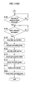
- this holder 4 activates a lever or the like of the detecting switch 19, so that the arrival of the transported negative sheet holder 4 may be detected (step #100). Then, based on this detection by the detecting switch 19, the negative sensor 22 is turned ON, then, this sensor 22 detects presence/absence of a negative film strip 5 within the first row pocket 4b of the holder 4 (step #101). By synchronizing the detection operation by the negative sensor 22 with the operation of the detecting switch 19, the detection of the negative film 5 may be effected in a reliable manner.
- the negative sheet holder 4 usually has some printing on the surface thereof and the above construction allows the detection of presence/absence of the negative film 5 at a portion free from such printing. To do this, the detecting switch 19 and the negative sensor 22 should be arranged appropriately with a predetermined distance therebetween.
- the discharging guide 14 is activated even if the negative film strips 5 are inserted into the second or subsequent rows 4c, 4d... (step #117). This is because the take-up unit 2 is disabled from taking up the negative sheet holder 4 if no negative film strip 5 is present in the first row 4b of the holder 4. Further, the detection at the first row 4b is advantageous for allowing early determination on whether to discharge the holder 4 or not.
- the discharging guide 14 is pivotally driven counter-clockwise about the pivot shaft 14a from position shown in Fig. 5 to the further position shown in Fig. 6 retracted away from the transport passage.
- the press roller 16 In association with this operation of the discharging guide 14, the press roller 16 too is driven counter-clockwise by its own weight or by means of an urging force from an unillustrated spring, so as to move the leading end 4e of the negative sheet holder 4 from the transport passage to a discharge passage.
- the drive roller group 10 if the drive roller group 10 is further driven, the negative sheet holder 4 is completely discharged from the transport passage.
- the negative sensor 22 detects presence of the negative film strip 5 within the first row 4b of the holder 4, then, this holder 4 is transported. Then, as shown in Fig. 7, when the leading end 4e of the holder 4 comes to the position of the detecting switch 20, the leading end 4e activates the lever of the detecting switch 20, whereby the arrival of the leading end 4e of the negative sheet holder 4 is detected (step #102). Based on this detection result, as shown in Fig. 8, the guide 15 is pivotally driven clockwise about the pivot shaft 15a from the retracted position shown in Figs. 5 through 7 to the guiding position (step #103). This arrangement of normally retracting the guide 15, the take-up member 30 may be disposed closer to the transport unit 1, thereby to allow the entire handling apparatus compact.
- the leading end 4e of the holder 4 is inserted between the pair of take-up bars 30c.
- the pair of take-up bars 30c are arranged one above the other across the transport passage.
- the leading end 4e of the negative sheet holder 4 is detected by the sensor 34 (step #104). Based upon this detection result by the sensor 34, the guide 15 is again returned from the guiding position to the retracted position (step #105). This returning operation is done for the purpose of not interfering with the subsequent take-up operation.
- the take-up member 30 is rotated counter-clockwise as indicated by the arrow in Fig. 9 (step #106).
- the velocity of this rotation is set so as not to apply an excessive tension on the holder 4.
- the first row 4b of the negative sheet holder 4 is inserted between the pair of take-up bars 30c and then the take-up operation of the negative sheet holder 4 is initiated.
- the process of this take-up operation is continuously illustrated in Figs. 15(a), (b) (c) and (d).
- this pushes the first row 4b of the negative sheet holder 4 to rotate it, whereby the take-up operation proceeds.
- the taken-up condition of the negative sheet holder 4 on the take-up member 30 is illustrated in Fig. 10.
- the holder 4 may be taken up by folding it at this perforation. That is, the right and left edges of the taken-up negative sheet holder 4 illustrated in Fig. 10 do not contain the negative film 5, so that these edges are slightly folded.
- the take-up width is set to substantially correspond to one row of the negative sheet holder 4. Accordingly, the distance between the pair of take-up bars 30c too is set so as to provide the above function.
- the number of rows of the holder 4 differs for each consumer's order. Therefore, the feature of taking-up the holder 4 by each order amount provides the advantage of allowing setting of same transport conditions for the holder 4.
- the sheet pressing plate 35 is driven clockwise about the pivot shaft 35a from the retracted inoperative position shown in Fig. 8 to the operative position shown in Fig. 9 (step #107).
- this pressing plate 35 has elastic resilience, the negative sheet holder 4 may be kept pressed by the elastic resilience of the plate 35 during the take-up operation. Further, after completion of the take-up operation too, the plate 35 keeps pressing a rear end portion 4f of the negative sheet holder 4 so as to prevent loosening and unwinding of the taken-up negative sheet holder 4.
- the take-up member 30 gradually takes up the negative sheet holder 4, a rear end portion 4f of this holder 4 is detected by the detecting switch 20. Then, when the beam transmitted from the beam emitter 33a of the END sensor 33 is detected two times by its beam receiver 33b, the rotation of the take-up member 30 is stopped (steps #108, #109, #110). More particularly, after the detection by the detection switch 20, the take-up member 30 is rotated for one time. With this, after completion of the take-up operation, the sheet pressing plate 35 may press the holder 4 in such a manner that the rear end portion 4f of the holder 4 is oriented upwards. As shown in Fig. 10, upon completion of the take-up operation, the revolution of the pair of take-up bars 30c is stopped so that the bars 30c may be located horizontally side by side.
- a discharging operation of the taken-up negative sheet holder 4 will be described.
- the movable guide 43 is slided from a position denoted by broken lines in Fig. 11 to a further position denoted by solid lines in the same figure (step #111).
- a support plate 40 shown in Fig. 1 is slided in the direction of arrow in Fig. 11.
- a follower roller 45 connected integrally to the push-out bar 41 is guided by the inclined face 47, whereby the push-out bar 41 is pivoted clockwise.
- the push-out bar 41 is shifted from the horizontal posture to the vertical posture (step #112). Under this vertical posture, the contact face 41b pushes a side end portion 4g of the negative sheet holder 4 and the holder 4 is pushed and discharged from the take-up bars 30c (step #113). Then, the negative sheet holder 4 is placed on the receiver plate 44, as illustrated in Fig. 12.
- the movable guide 43 Upon completion of the discharging of the holder 4 onto the receiver plate 44, as illustrated in Fig. 13, the movable guide 43 is returned to the initial position (step #114). Thereafter, the push-out bar 41 too is returned to its initial position (step #115). Further, the sheet pressing plate 35 is returned to the retracted position (step #116). This is the initial condition shown in Fig. 4. Incidentally, the timing of returning the sheet pressing plate 35 is not limited to that described above. This returning operation may be effected anytime after the holder 4 has exited from the take-up bars 30c.
- the folded negative sheet holder 4 is inserted, at a separate site, into a bag together with its corresponding photographic prints to be provided to the consumer.
Landscapes
- Physics & Mathematics (AREA)
- General Physics & Mathematics (AREA)
- Photographic Processing Devices Using Wet Methods (AREA)
Claims (9)
- Filmbogenträger-Handhabungsvorrichtung (100) zum Aufnehmen eines Filmbogenträgers (4), in welchem für eine Bestellmenge zugeschnittene Fotofilmstreifen (5) aufbewahrt werden, mit:gekennzeichnet durcheiner Aufnahmeeinrichtung (30) zum Aufnehmen des Filmbogenträgers um eine vorbestimmte Menge, die einer bestimmten Anzahl von Reihen der Filmbogenträger entspricht;
eine Filmerfassungseinrichtung (22) zum Erfassen der Anwesenheit/Abwesenheit des Films (5) innerhalb des transportierten Filmbogenträgers, bevor der Träger durch die Aufnahmeeinrichtung aufgenommen wird. - Filmbogenträger-Handhabungsvorrichtung nach Anspruch 1,
gekennzeichnet durch
eine Transporteinrichtung (10, 11, 12) zum Transportieren des Filmbogenträgers zur Aufnahmeeinrichtung entlang eines Transportwegs, wenn die Filmerfassungseinrichtung (22) die Anwesenheit des Films (5) erfasst; und
eine Auswurfeinrichtung (16) zum Auswerfen des Filmbogenträgers (4) aus dem Transportweg, wenn die Filmerfassungseinrichtung (22) die Abwesenheit des Films (5) erfasst. - Filmbogenträger-Handhabungsvorrichtung nach Anspruch 1,
gekennzeichnet durch
eine Bogenerfassungseinrichtung (19) zum Erfassen der Anwesenheit/Abwesenheit des transportierten Filmbogenträgers (4), wobei die Filmerfassungseinrichtung (22) in Aktion tritt, wenn die Bogenerfassungseinrichtung (19) die Anwesenheit des Filmbogenträgers (4) erfasst. - Filmbogenträger-Handhabungsvorrichtung nach Anspruch 1,
dadurch gekennzeichnet, dass
die Filmerfassungseinrichtung (22) mehrere entlang einer Breite des transportiert werdenden Filmbogenträgers (4) angeordnete Sensoren aufweist und die Filmerfassungseinrichtung (22) so angeordnet ist, dass sie die Erfassung des Films (5) in einer ersten Reihe (4b) des Filmbogenträgers (4) durchführt. - Filmbogenträger-Handhabungsvorrichtung nach Anspruch 1,
dadurch gekennzeichnet, dass
die Aufnahmeeinrichtung (30) ein Paar Aufnahmestangen (30c) aufweist, die exzentrisch im Verhältnis zu einer gemeinsamen Umdrehungsachse angeordnet sind, so dass ein vorderes Ende des Filmbogenträgers (4) zwischen das Paar Aufnahmestangen (30c) eingeführt wird und die erste Reihe (4b) des Filmbogenträgers (4) in Verbindung mit einer konzentrischen Umdrehung der Aufnahmestangen (30c) zum Schieben der ersten Reihe (4b) des Filmbogenträgers (4) aufgenommen wird. - Filmbogenträger-Handhabungsvorrichtung nach Anspruch 5,
dadurch gekennzeichnet, dass
jede Aufnahmestange (30c) eine rutschhemmende Einrichtung (30d) aufweist, die aus einem Gummielement an einem Teil der Stange gebildet ist, welcher den Filmbogenträger (4) kontaktiert. - Filmbogenträger-Handhabungsvorrichtung nach Anspruch 5,
dadurch gekennzeichnet, dass
das Paar Aufnahmestangen (30c) selektiv eine erste Position einnimmt, um das Einschieben des vorderen Endes des Filmbogenträgers (4) zwischen den Aufnahmestangen zu erlauben, und eine zweite Position, um das Auswerfen des aufgenommenen Filmbogenträgers aus den Aufnahmestangen (30c) zu erlauben. - Filmbogenträger-Handhabungsvorrichtung nach Anspruch 1,
gekennzeichnet durch
eine erste Auswurfeinrichtung (41) zum Auswerfen des Filmbogenträgers (4) nach dem Aufnahmevorgang durch die Aufnahmeeinrichtung (30);
wobei die erste Auswurfeinrichtung (41) eine Ausstoßstange zum Herausschieben des aufgenommenen Filmbogenträgers (4) in einer Richtung im rechten Winkel zur Transportrichtung des Filmbogenträgers (4) aufweist, wobei die Ausstoßstange selektiv eine passive Position einnimmt, die entfernt von einem Arbeitsbereich der Aufnahmeeinrichtung (30) während ihres Aufnahmevorgangs des Filmbogenträgers (4) liegt, und eine Arbeitsposition zum Ausstoßen des aufgenommenen Filmbogenträgers (4) nach Abschluss des Aufnahmevorgangs. - Verfahren zur Handhabung eines Filmbogenträgers, in welchem für eine Bestellmenge zurechtgeschnittene Fotofilmstreifen aufbewahrt sind, mit den folgenden Schritten:gekennzeichnet durch die folgenden Schritte:Transportieren des Filmbogenträgers;Erfassen der Anwesenheit/Abwesenheit des Films (5) in dem Filmbogenträger (4);Transportieren des Filmbogenträgers (4) zu einer Aufnahmeeinrichtung (30) entlang eines Transportwegs, wenn die Anwesenheit des Films (5) durch den Verfahrensschritt des Erfassens festgestellt wurde; undAufnehmen des Filmbogenträgers (4) um eine vorbestimmte Menge, die einer bestimmten Anzahl von Reihen des Filmbogenträgers (4) entspricht.
Applications Claiming Priority (3)
| Application Number | Priority Date | Filing Date | Title |
|---|---|---|---|
| JP3514/96 | 1996-01-12 | ||
| JP00351496A JP3329427B2 (ja) | 1996-01-12 | 1996-01-12 | フィルム収納シート取扱装置及び取扱方法 |
| JP351496 | 1996-01-12 |
Publications (2)
| Publication Number | Publication Date |
|---|---|
| EP0784231A1 EP0784231A1 (de) | 1997-07-16 |
| EP0784231B1 true EP0784231B1 (de) | 2003-06-11 |
Family
ID=11559480
Family Applications (1)
| Application Number | Title | Priority Date | Filing Date |
|---|---|---|---|
| EP97100244A Expired - Lifetime EP0784231B1 (de) | 1996-01-12 | 1997-01-09 | Gerät und Verfahren zur Handhabung von Filmbögenträgern |
Country Status (4)
| Country | Link |
|---|---|
| US (1) | US5815761A (de) |
| EP (1) | EP0784231B1 (de) |
| JP (1) | JP3329427B2 (de) |
| DE (1) | DE69722685T2 (de) |
Families Citing this family (1)
| Publication number | Priority date | Publication date | Assignee | Title |
|---|---|---|---|---|
| ITMI20012234A1 (it) * | 2001-10-24 | 2003-04-24 | Fotoba Int Srl | Apparecchiatura di finitura e taglio automatico di immagini su fogli di carta ed altri supporti grafici e fotografici |
Family Cites Families (5)
| Publication number | Priority date | Publication date | Assignee | Title |
|---|---|---|---|---|
| US4805039A (en) * | 1984-11-19 | 1989-02-14 | Fuji Photo Film Co., Ltd. | Index sheet, method for making same, package of same with image recording medium, and container for same together with image recording medium |
| US4720733A (en) * | 1985-07-19 | 1988-01-19 | Fuji Photo Film Co., Ltd. | Photographic print set and method of producing the same |
| US5031773A (en) * | 1990-06-15 | 1991-07-16 | Eastman Kodak Company | Photographic image set |
| JPH0511428A (ja) * | 1991-07-01 | 1993-01-22 | Fuji Photo Film Co Ltd | ネガシート折畳み装置 |
| JPH06161087A (ja) * | 1992-11-26 | 1994-06-07 | Fuji Photo Film Co Ltd | フイルム収納シートの折り畳み装置 |
-
1996
- 1996-01-12 JP JP00351496A patent/JP3329427B2/ja not_active Expired - Fee Related
-
1997
- 1997-01-09 US US08/780,873 patent/US5815761A/en not_active Expired - Fee Related
- 1997-01-09 DE DE69722685T patent/DE69722685T2/de not_active Expired - Fee Related
- 1997-01-09 EP EP97100244A patent/EP0784231B1/de not_active Expired - Lifetime
Also Published As
| Publication number | Publication date |
|---|---|
| DE69722685D1 (de) | 2003-07-17 |
| DE69722685T2 (de) | 2004-04-29 |
| JPH09197646A (ja) | 1997-07-31 |
| JP3329427B2 (ja) | 2002-09-30 |
| EP0784231A1 (de) | 1997-07-16 |
| US5815761A (en) | 1998-09-29 |
Similar Documents
| Publication | Publication Date | Title |
|---|---|---|
| US5090318A (en) | Printer with sheet feeding apparatus | |
| EP0784231B1 (de) | Gerät und Verfahren zur Handhabung von Filmbögenträgern | |
| US6474387B1 (en) | Sorting device | |
| EP0709217A1 (de) | Schablonendruckmaschine | |
| EP0550916B1 (de) | Vorrichtung zum Zuführen von Negativfilmen | |
| US5153639A (en) | Film supplying apparatus | |
| US5638157A (en) | Film processing apparatus | |
| JPH0643622A (ja) | 写真照合袋詰め装置 | |
| JPS63316843A (ja) | 写真焼付装置用印画紙搬送装置 | |
| JP2710293B2 (ja) | 通帳プリンタの搬送装置 | |
| KR100188351B1 (ko) | 사진 프린터 | |
| JPH02282163A (ja) | 仕分け装置 | |
| JP2664553B2 (ja) | ネガフィルム供給カートリッジ | |
| JP2666083B2 (ja) | フィルム搬送装置 | |
| JP2000003026A (ja) | フィルム収納シート取扱装置 | |
| JPH0310500Y2 (de) | ||
| JP2833538B2 (ja) | フィルム供給装置 | |
| JP3208924B2 (ja) | 写真処理装置 | |
| JP2000162755A (ja) | ネガシート処理システム | |
| JPH092676A (ja) | 紙葉類処理装置 | |
| JPH04318846A (ja) | 自動照合袋詰め装置 | |
| JPH06347991A (ja) | ペーパカッタの集積機構 | |
| JPH11199115A (ja) | シート状材料収納装置 | |
| JPH0252843A (ja) | 蛇行検出装置及び蛇行修正方法 | |
| JPS63154560A (ja) | 記録装置 |
Legal Events
| Date | Code | Title | Description |
|---|---|---|---|
| PUAI | Public reference made under article 153(3) epc to a published international application that has entered the european phase |
Free format text: ORIGINAL CODE: 0009012 |
|
| 17P | Request for examination filed |
Effective date: 19970111 |
|
| AK | Designated contracting states |
Kind code of ref document: A1 Designated state(s): DE FR GB |
|
| GRAH | Despatch of communication of intention to grant a patent |
Free format text: ORIGINAL CODE: EPIDOS IGRA |
|
| GRAH | Despatch of communication of intention to grant a patent |
Free format text: ORIGINAL CODE: EPIDOS IGRA |
|
| GRAA | (expected) grant |
Free format text: ORIGINAL CODE: 0009210 |
|
| AK | Designated contracting states |
Designated state(s): DE FR GB |
|
| REG | Reference to a national code |
Ref country code: GB Ref legal event code: FG4D |
|
| REF | Corresponds to: |
Ref document number: 69722685 Country of ref document: DE Date of ref document: 20030717 Kind code of ref document: P |
|
| PGFP | Annual fee paid to national office [announced via postgrant information from national office to epo] |
Ref country code: GB Payment date: 20040107 Year of fee payment: 8 |
|
| PGFP | Annual fee paid to national office [announced via postgrant information from national office to epo] |
Ref country code: FR Payment date: 20040108 Year of fee payment: 8 |
|
| PGFP | Annual fee paid to national office [announced via postgrant information from national office to epo] |
Ref country code: DE Payment date: 20040122 Year of fee payment: 8 |
|
| ET | Fr: translation filed | ||
| PLBE | No opposition filed within time limit |
Free format text: ORIGINAL CODE: 0009261 |
|
| STAA | Information on the status of an ep patent application or granted ep patent |
Free format text: STATUS: NO OPPOSITION FILED WITHIN TIME LIMIT |
|
| 26N | No opposition filed |
Effective date: 20040312 |
|
| PG25 | Lapsed in a contracting state [announced via postgrant information from national office to epo] |
Ref country code: GB Free format text: LAPSE BECAUSE OF NON-PAYMENT OF DUE FEES Effective date: 20050109 |
|
| PG25 | Lapsed in a contracting state [announced via postgrant information from national office to epo] |
Ref country code: DE Free format text: LAPSE BECAUSE OF NON-PAYMENT OF DUE FEES Effective date: 20050802 |
|
| GBPC | Gb: european patent ceased through non-payment of renewal fee |
Effective date: 20050109 |
|
| PG25 | Lapsed in a contracting state [announced via postgrant information from national office to epo] |
Ref country code: FR Free format text: LAPSE BECAUSE OF NON-PAYMENT OF DUE FEES Effective date: 20050930 |
|
| REG | Reference to a national code |
Ref country code: FR Ref legal event code: ST |