EP0709217A1 - Schablonendruckmaschine - Google Patents
Schablonendruckmaschine Download PDFInfo
- Publication number
- EP0709217A1 EP0709217A1 EP95307544A EP95307544A EP0709217A1 EP 0709217 A1 EP0709217 A1 EP 0709217A1 EP 95307544 A EP95307544 A EP 95307544A EP 95307544 A EP95307544 A EP 95307544A EP 0709217 A1 EP0709217 A1 EP 0709217A1
- Authority
- EP
- European Patent Office
- Prior art keywords
- stencil sheet
- stencil
- printing drum
- printing
- sheet
- Prior art date
- Legal status (The legal status is an assumption and is not a legal conclusion. Google has not performed a legal analysis and makes no representation as to the accuracy of the status listed.)
- Granted
Links
Images



Classifications
-
- B—PERFORMING OPERATIONS; TRANSPORTING
- B41—PRINTING; LINING MACHINES; TYPEWRITERS; STAMPS
- B41L—APPARATUS OR DEVICES FOR MANIFOLDING, DUPLICATING OR PRINTING FOR OFFICE OR OTHER COMMERCIAL PURPOSES; ADDRESSING MACHINES OR LIKE SERIES-PRINTING MACHINES
- B41L29/00—Devices for attaching printing elements or formes to supports
- B41L29/12—Devices for attaching printing elements or formes to supports for attaching flexible printing formes
- B41L29/14—Clamping devices
- B41L29/16—Clamping devices operating automatically during operation of rotary machines to attach the printing formes to the forme cylinders
-
- B—PERFORMING OPERATIONS; TRANSPORTING
- B41—PRINTING; LINING MACHINES; TYPEWRITERS; STAMPS
- B41L—APPARATUS OR DEVICES FOR MANIFOLDING, DUPLICATING OR PRINTING FOR OFFICE OR OTHER COMMERCIAL PURPOSES; ADDRESSING MACHINES OR LIKE SERIES-PRINTING MACHINES
- B41L13/00—Stencilling apparatus for office or other commercial use
- B41L13/04—Stencilling apparatus for office or other commercial use with curved or rotary stencil carriers
- B41L13/06—Stencilling apparatus for office or other commercial use with curved or rotary stencil carriers with a single cylinder carrying the stencil
Definitions
- the present invention relates to a stencil printing machine which has high performance of wrapping a stencil sheet for stencil printing around a printing drum and discharging a used stencil sheet to a stencil discharge section.
- a stencil sheet to be used in a stencil printing machine is generally of such a construction that a substrate for backing a resin film is cemented with an adhesive to the resin film. That is, the stencil sheet is produced generally by cementing a long, continuous belt-like substrate to a long, continuous belt-like resin film as disclosed for example in Japanese Patent Laid-Open No. Hei 5-309968.
- the cementing of the substrate to the resin film is done with a fixed tension applied in the longitudinal direction to the resin film and the substrate. Therefore, the tension of either of the resin film and the substrate requires to be changed according to its extensibility (modulus in tension); the stencil sheet thus produced is likely to curl longitudinally after cementing.
- the roll-type stencil sheet is generally of the cylindrical type that a long belt-like stencil sheet is wound on a core tube.
- the long belt-like stencil sheet wound on the core tube in the shape of roll will get curled with the lapse of time.
- the curling occurs in the longitudinal direction of the stencil sheet.
- increasing the core tube diameter will increase the overall volume of the roll of stencil sheet and accordingly will require the use of a larger-size stencil printing machine itself which holds the roll inside.
- Fig. 4 shows a part of the constitution of a prior art stencil printing machine.
- the roll of the stencil sheet S and a printing drum 100 are arranged parallel.
- the long belt-like stencil sheet paid out from the roll of the stencil sheet S is, after perforation, held by a clamp means 101 along a transverse direction (direction of width) intersecting with the direction of unwinding, then being fixed on the peripheral surface of the printing drum 100.
- the long belt-like stencil sheet S wound in a roll shape is clamped by the clamp means 101 along the direction of width intersecting at right angles with the longitudinal direction of a curled sheet, and is secured on the printing drum 100 along the generating line of the printing drum 100. Therefore, the operation of wrapping and removing the stencil sheet S in relation to the printing drum 100 is largely affected by the longitudinal curl.
- the clamp means 101 sometimes fails to hold the stencil sheet S as indicated by an imaginary line in Fig. 4, failing in wrapping the stencil sheet around the printing drum 100.
- the stencil sheet S after printing, when removed from the printing drum 100 and conveyed to a stencil discharge section 102 is greatly affected by the longitudinal curl, resulting in a failure in taking up the stencil sheet by a discharge roller 103 of the stencil discharge section 102.
- the present invention seeks to provide the stencil printing machine that facilitates wrapping the perforated stencil sheet around a printing drum and removing a used stencil sheet from the printing drum and discharging it into a stencil discharge section.
- the stencil printing machine comprises a stencil sheet composed of a resin film and a substrate and curled in a specific direction; a perforating section for perforating the stencil sheet; a printing drum wrapped with the stencil sheet perforated at the perforating section, and driven to rotate about the axis of itself; a conveying means for carrying the stencil sheet to the printing drum in such a manner that the edge in the specific direction of the stencil sheet perforated at the perforating section will be substantially parallel with one generating line of the printing drum; a clamp means for fastening, along the one generating line of the printing drum, the edge of the stencil sheet that has been carried by the conveying means to the printing drum; and the stencil sheet discharge section for removing the stencil sheet from the printing drum after completion of printing.
- the stencil printing machine according to the second aspect of the present invention is characterized in that, in the stencil printing machine of the first aspect, the axis of the stencil sheet wound in a cylindrical shape intersects at right angles with the axis of the printing drum.
- the stencil printing machine according to the third aspect of the present invention is characterized in that, in the stencil printing machine of the first aspect, a reinforcing member is mounted along the specific direction in other part than a printing area of the stencil sheet, and is fixed by the clamp means on the printing drum.
- the stencil sheet perforated at the perforating section is fixed by the clamp means on the printing drum in such a manner that the specific direction in which the stencil sheet curls largely will be along the generating line of the printing drum.
- the stencil sheet can be securely clamped by the clamp means because of the presence of little curling of the stencil sheet in the circumferential direction of the printing drum.
- the stencil sheet is removed from the printing drum by means of the stencil discharge section. Since the stencil sheet curls little in the circumferential direction of the printing drum, the stencil discharge section can properly hold the edge of the stencil sheet.
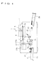
- FIG. 1 is a schematic view showing one embodiment of a stencil printing machine 1.
- An original image reading section 5 including an image scanner 3 functions to read an original image to be printed and outputs the image as an original image data.
- a perforating section 7 includes a perforating device for forming a perforated image in a stencil sheet S in accordance with the original image data thus read by the original image reading section 5.
- a thermal head is usable.
- the stencil sheet S perforated at the perforating section 7 has been wrapped around a printing drum 9 having an ink-pervious peripheral wall.
- the printing drum 9 is driven about the axis of itself by means of a driving means now shown.
- an ink feeding means for feeding ink to the inner peripheral surface of the printing drum 9.
- a clamp means 11 On the outer peripheral surface of the printing drum 9 is provided a clamp means 11. The clamp means 11 is used to clamp one end of the stencil sheet S along one generating line of the cylindrical printing drum 9.
- the impression member 13 is a rotatable roller which moves up and down in synchronization with the rotation of the printing drum 9.
- the impression member 13 serves to hold, in cooperation with the printing drum 9, a printed paper P that has been carried simultaneously with the rotation of the printing drum 9, then printing is done by transferring the ink from the printing drum 9 to the paper P to be printed.
- the printing paper P on the paper feed table 15 is separated one by one by means of a paper separating roller 17, then being fed between the printing drum 9 and the impression member 13 by means of a paper feed timing roller 19 simultaneously with printing operation.
- a separating claw 21 provided in the vicinity of the printing drum 9 separates the printed paper P pressed against the printing drum 9 by the impression member 13, from the outer peripheral surface of the printing drum 9.
- the printed paper P stripped from the printing drum 9 by means of the separating claw 21 is discharged to a delivery table 25 by a belt conveyor mechanism of the conveyor apparatus 23.
- a stencil discharge section 27 disposed near the printing drum 9 has a stencil discharge roller 27a which strips the used stencil sheet S from the outer peripheral surface of the printing drum 9 while holding one end thereof, and a box-shaped storing section 27b for storing the stencil sheet S removed from the stencil discharge roller 27a.
- the stencil sheet S used in the present embodiment is a stencil sheet S of a roll type that a long belt-like stencil sheet is wound in a cylindrical form.
- the stencil sheet S has a curl caused by winding in a longitudinal direction and a curl caused by the stencil sheet structure that the substrate and the resin film are cemented.
- the stencil sheet S of roll type is arranged approximately horizontally so that its axis will meet at right angles with the axis of the printing drum 9 and its one end will be disposed in the vicinity of the top section of the printing drum 9.
- the printing sheet S is loaded near the printing drum 9 so that the inner side of a rolled stencil sheet will face the peripheral surface of the printing drum when fed out toward the printing drum 9.
- a conveyor belt 31 as a conveying means in a position ahead of the cutter unit 29 in the direction the stencil sheet S is paid out.
- the roll of the stencil sheet S as shown in Fig. 2, is fed out along the direction of the axis of the printing drum 9, being perforated at the perforating section 7.
- the stencil sheet S when perforated, is conveyed on the conveyor belt 31 at a speed exactly corresponding to the perforating operation of the perforating section 7.
- the long belt-like stencil sheet S After perforation, the long belt-like stencil sheet S reaches a specific position, where the cutter unit 29 cuts the stencil sheet S along the transverse direction (direction of width).
- the stencil sheet S thus cut to an appropriate length is secured by the clamp means 11 on the printing drum 9 along its longitudinal direction. Then, the printing drum 9 rotates in a specific direction indicated in Figs. 1 and 2, wrapping the stencil sheet S around the peripheral surface thereof.
- the stencil sheet is discharged. As shown in Fig. 3, first the clamp means 11 releases the stencil sheet S, and then the printing drum 9 rotates in an illustrated direction. The leading edge of the stencil sheet S thus released approaches the stencil discharge roller 27a of the stencil discharge section 27. The stencil discharge roller 27a is rotated to strip the used stencil sheet S from the peripheral surface of the printing drum 9, discharging the stencil sheet S into the storing section 27b of the stencil discharge section 27.
- the edge in the longitudinal direction of a curled stencil sheet S is secured by the clamp means 11 along one generating line of the printing drum 9. Therefore, the transverse direction (direction of width) in which the stencil sheet S is less curled agrees with the direction of rotation (circumferential direction) of the printing drum 9.
- the clamp means 11 can securely clamp one end of the stencil sheet S on the printing drum 9.
- the stencil sheet S has a curl in the area close to the core tube side, resulting in a specially heavy curling in the longitudinal direction.
- the stencil sheet S of the present embodiment the stencil sheet S can be fixed exactly in a specific position on the printing drum 9.
- the clamp means will sometimes fail to clamp the stencil sheet S; according to the stencil printing machine 1 of the present embodiment such a failure in clamping will not occur.
- the stencil discharge roller 27a can exactly receive one end of the stencil sheet S because of little curling of the stencil sheet S on the printing drum 9, and can exactly strip the used stencil sheet S from the printing drum 9 and discard it.
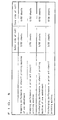
- Evaluation was conducted on the performance of wrapping the stencil sheet around the printing drum and the performance of discharging the stencil sheet from the printing drum for comparison between the stencil printing machine 1 of the present embodiment and a prior art stencil printing machine explained by referring to Fig. 4.
- the stencil sheet wrapping performance was evaluated on 50 sheets taken from the outer side of a stencil sheet roll where the stencil sheet is relatively little curled, and on another 50 sheets taken from the core side of the same roll where the stencil sheet is relatively heavily curled. The number of stencil sheets that could not be fixed on the printing drum is given as an evaluation result.
- the stencil sheet discharging performance was also evaluated on 50 sheets taken from either of the outer and core sides of the stencil sheet roll as in the case of the wrapping performance evaluation stated above.
- the stencil S used in the stencil printing machine 1 explained above is of a roll type; it should be noticed, however, that stencil sheets are also applicable to the stencil printing machine 1 of the present invention.
- the resin film of the stencil sheet S used in the present invention is a film of a thermoplastic resin which can be perforated by the use of a heat source such as a thermal head.
- the thermoplastic resin may be for example polyethylene, polypropylene, polyvinyl chloride, polyvinylidene chloride, polyester, polystyrene, polyurethane, polycarbonate, acrylic resin, and silicone resin, of which polyvinylidene chloride and polyester are specially desirable. It is also possible to use a resin film perforable by melting through an ink-jet system other than the heat source such as the thermal head.
- thin paper, resin sheet, printing paper, etc. are usable.
- the curling quality R is measured by the following procedure.
- a stencil sheet is pasted on a 40 mm by 40 mm frame with the resin film side up in such a manner that the longitudinal and transverse directions of the stencil sheet will be in parallel with each side of the frame.
- the frame and the stencil sheet are cut along the diagonal line of the frame.
- the radius of a curl appearing along the cut line of the stencil sheet is measured as the curling quality R.
- the same measurement was conducted on the outside and core side of winding of the stencil sheet. A result of the measurement is shown in Fig. 6.
- the stencil sheet is thus sharply curled along the longitudinal direction thereof. Accordingly, the performance of wrapping and discharging the stencil sheet in relation to the cylindrical printing drum can be improved by restricting the curling of the stencil sheet with a reinforcing member mounted along the longitudinal direction other than the printed surface of the stencil sheet.
- a reinforcing member mounted along the longitudinal direction other than the printed surface of the stencil sheet.
- a member having enough specific rigidity to restrict the curling of the stencil sheet is usable.
- paper and synthetic resin film can be used.
- the reinforcing member is applicable to restraining the curling of either of the roll-type and thin-paper stencil sheets.
- the stencil sheet with such a reinforcing member secured with the clamp means in the stencil printing machine 1 of the present embodiment is hardly subject to curling on the printing drum 9 and is further improved in the performance of wrapping and discharging the stencil sheet on the cylindrical printing drum of the stencil printing machine 1.
- the stencil sheet being secured on the printing drum by a clamp means along the longitudinal direction in which the stencil sheet heavily curls, will be little subject to curling on the printing drum, thereby improving the wrapping and discharging performance of the stencil sheet.
Landscapes
- Manufacture Or Reproduction Of Printing Formes (AREA)
Applications Claiming Priority (2)
| Application Number | Priority Date | Filing Date | Title |
|---|---|---|---|
| JP6258249A JPH08118775A (ja) | 1994-10-24 | 1994-10-24 | 孔版印刷装置 |
| JP258249/94 | 1994-10-24 |
Publications (2)
| Publication Number | Publication Date |
|---|---|
| EP0709217A1 true EP0709217A1 (de) | 1996-05-01 |
| EP0709217B1 EP0709217B1 (de) | 1999-01-27 |
Family
ID=17317609
Family Applications (1)
| Application Number | Title | Priority Date | Filing Date |
|---|---|---|---|
| EP95307544A Expired - Lifetime EP0709217B1 (de) | 1994-10-24 | 1995-10-24 | Schablonendruckmaschine |
Country Status (4)
| Country | Link |
|---|---|
| US (1) | US5671669A (de) |
| EP (1) | EP0709217B1 (de) |
| JP (1) | JPH08118775A (de) |
| DE (1) | DE69507569T2 (de) |
Families Citing this family (6)
| Publication number | Priority date | Publication date | Assignee | Title |
|---|---|---|---|---|
| GB2321877B (en) * | 1995-07-31 | 1998-10-21 | Tohoku Riko Kk | Stencil perforating device |
| JP3685963B2 (ja) * | 1999-09-17 | 2005-08-24 | 理想科学工業株式会社 | 印刷装置の製版着版方法 |
| WO2001050229A2 (en) * | 1999-12-30 | 2001-07-12 | B4Bpartner, Inc. | Electronic safe deposit box |
| JP3338822B2 (ja) * | 2000-02-24 | 2002-10-28 | 理想科学工業株式会社 | プリンタドライバ |
| US20040024714A1 (en) * | 2000-12-29 | 2004-02-05 | Wells Thomas E. | Electronic safe deposit box |
| US6843732B1 (en) * | 2003-12-23 | 2005-01-18 | Ben Huang | Multi-segment single panel grip |
Citations (2)
| Publication number | Priority date | Publication date | Assignee | Title |
|---|---|---|---|---|
| JPH05309968A (ja) | 1992-05-01 | 1993-11-22 | Dainippon Printing Co Ltd | 感熱謄写版原紙及びその製造方法 |
| GB2267060A (en) * | 1992-05-19 | 1993-11-24 | Ricoh Kk | Master making device for a stencil printer |
Family Cites Families (5)
| Publication number | Priority date | Publication date | Assignee | Title |
|---|---|---|---|---|
| JPS5916789A (ja) * | 1982-07-19 | 1984-01-27 | Matsushita Electric Ind Co Ltd | ロ−ル式孔版印刷用原紙 |
| JPS5916787A (ja) * | 1982-07-19 | 1984-01-27 | Matsushita Electric Ind Co Ltd | ロ−ル式感熱孔版印刷用原紙 |
| JPS5916788A (ja) * | 1982-07-19 | 1984-01-27 | Matsushita Electric Ind Co Ltd | ロ−ル式感熱孔版印刷用原紙 |
| GB2202186A (en) * | 1987-03-12 | 1988-09-21 | Riso Kagaku Corp | Printing stencil |
| US5207157A (en) * | 1989-12-22 | 1993-05-04 | Ricoh Company, Ltd. | Control device for a stencil duplicating machine |
-
1994
- 1994-10-24 JP JP6258249A patent/JPH08118775A/ja active Pending
-
1995
- 1995-10-17 US US08/543,937 patent/US5671669A/en not_active Expired - Fee Related
- 1995-10-24 DE DE69507569T patent/DE69507569T2/de not_active Expired - Fee Related
- 1995-10-24 EP EP95307544A patent/EP0709217B1/de not_active Expired - Lifetime
Patent Citations (2)
| Publication number | Priority date | Publication date | Assignee | Title |
|---|---|---|---|---|
| JPH05309968A (ja) | 1992-05-01 | 1993-11-22 | Dainippon Printing Co Ltd | 感熱謄写版原紙及びその製造方法 |
| GB2267060A (en) * | 1992-05-19 | 1993-11-24 | Ricoh Kk | Master making device for a stencil printer |
Also Published As
| Publication number | Publication date |
|---|---|
| JPH08118775A (ja) | 1996-05-14 |
| DE69507569D1 (de) | 1999-03-11 |
| US5671669A (en) | 1997-09-30 |
| DE69507569T2 (de) | 1999-07-15 |
| EP0709217B1 (de) | 1999-01-27 |
Similar Documents
| Publication | Publication Date | Title |
|---|---|---|
| US5671669A (en) | Stencil conveying means adapted to convey a stencil sheet parallel to the axis of a printing drum | |
| EP0704313B1 (de) | Schablonendruckmaschine, Schablonenblatt und Schablonendruckmethode | |
| JP3549370B2 (ja) | カートリッジおよびこのカートリッジを用いた記録装置 | |
| JPH01320190A (ja) | 孔版印刷装置 | |
| JP3574382B2 (ja) | 印刷装置 | |
| US20010037736A1 (en) | Stencil printer system | |
| JP4246875B2 (ja) | 画像形成装置 | |
| JPS6270170A (ja) | 印画紙取扱い装置 | |
| JPH0611832Y2 (ja) | 製版印刷装置 | |
| JP2007245679A (ja) | 孔版印刷用原紙および孔版印刷装置 | |
| JP4994542B2 (ja) | テープ及びテーププリンタ | |
| JP4523427B2 (ja) | 印刷装置 | |
| JP4462707B2 (ja) | 製版装置および孔版印刷装置 | |
| JP2530837B2 (ja) | ウエブ巻取方法および装置 | |
| JPH0611831Y2 (ja) | 製版印刷装置 | |
| EP0784231B1 (de) | Gerät und Verfahren zur Handhabung von Filmbögenträgern | |
| JP2002037513A (ja) | 排紙台及びこれを用いた印刷装置 | |
| JP2597303B2 (ja) | 2巻の券用ロールを備えた発券装置 | |
| JP2007196492A (ja) | 孔版印刷用原紙および印刷方法ならびに孔版印刷装置 | |
| JPH05116401A (ja) | 印字装置 | |
| JPH0811415A (ja) | 孔版印刷装置 | |
| JP4425379B2 (ja) | 孔版印刷装置 | |
| JPH01122865A (ja) | 画像形成用シート移動方法及び画像形成用シート移動装置 | |
| JP3577144B2 (ja) | 孔版印刷装置の製版装置 | |
| JP2000147739A (ja) | フィルム収納シート案内ガイド及びこれを備えた写真処理装置 |
Legal Events
| Date | Code | Title | Description |
|---|---|---|---|
| PUAI | Public reference made under article 153(3) epc to a published international application that has entered the european phase |
Free format text: ORIGINAL CODE: 0009012 |
|
| AK | Designated contracting states |
Kind code of ref document: A1 Designated state(s): DE FR GB |
|
| 17P | Request for examination filed |
Effective date: 19960702 |
|
| 17Q | First examination report despatched |
Effective date: 19970523 |
|
| GRAG | Despatch of communication of intention to grant |
Free format text: ORIGINAL CODE: EPIDOS AGRA |
|
| GRAG | Despatch of communication of intention to grant |
Free format text: ORIGINAL CODE: EPIDOS AGRA |
|
| GRAH | Despatch of communication of intention to grant a patent |
Free format text: ORIGINAL CODE: EPIDOS IGRA |
|
| GRAH | Despatch of communication of intention to grant a patent |
Free format text: ORIGINAL CODE: EPIDOS IGRA |
|
| GRAA | (expected) grant |
Free format text: ORIGINAL CODE: 0009210 |
|
| AK | Designated contracting states |
Kind code of ref document: B1 Designated state(s): DE FR GB |
|
| REF | Corresponds to: |
Ref document number: 69507569 Country of ref document: DE Date of ref document: 19990311 |
|
| ET | Fr: translation filed | ||
| PLBE | No opposition filed within time limit |
Free format text: ORIGINAL CODE: 0009261 |
|
| STAA | Information on the status of an ep patent application or granted ep patent |
Free format text: STATUS: NO OPPOSITION FILED WITHIN TIME LIMIT |
|
| 26N | No opposition filed | ||
| REG | Reference to a national code |
Ref country code: GB Ref legal event code: IF02 |
|
| PGFP | Annual fee paid to national office [announced via postgrant information from national office to epo] |
Ref country code: FR Payment date: 20030922 Year of fee payment: 9 |
|
| PGFP | Annual fee paid to national office [announced via postgrant information from national office to epo] |
Ref country code: GB Payment date: 20031010 Year of fee payment: 9 |
|
| PGFP | Annual fee paid to national office [announced via postgrant information from national office to epo] |
Ref country code: DE Payment date: 20031230 Year of fee payment: 9 |
|
| PG25 | Lapsed in a contracting state [announced via postgrant information from national office to epo] |
Ref country code: GB Free format text: LAPSE BECAUSE OF NON-PAYMENT OF DUE FEES Effective date: 20041024 |
|
| PG25 | Lapsed in a contracting state [announced via postgrant information from national office to epo] |
Ref country code: DE Free format text: LAPSE BECAUSE OF NON-PAYMENT OF DUE FEES Effective date: 20050503 |
|
| GBPC | Gb: european patent ceased through non-payment of renewal fee |
Effective date: 20041024 |
|
| PG25 | Lapsed in a contracting state [announced via postgrant information from national office to epo] |
Ref country code: FR Free format text: LAPSE BECAUSE OF NON-PAYMENT OF DUE FEES Effective date: 20050630 |
|
| REG | Reference to a national code |
Ref country code: FR Ref legal event code: ST |