EP0784497B1 - Aufhebemittel verschaffende filterzellen und verwandte methoden - Google Patents
Aufhebemittel verschaffende filterzellen und verwandte methoden Download PDFInfo
- Publication number
- EP0784497B1 EP0784497B1 EP95937376A EP95937376A EP0784497B1 EP 0784497 B1 EP0784497 B1 EP 0784497B1 EP 95937376 A EP95937376 A EP 95937376A EP 95937376 A EP95937376 A EP 95937376A EP 0784497 B1 EP0784497 B1 EP 0784497B1
- Authority
- EP
- European Patent Office
- Prior art keywords
- cartridge
- housing
- filter
- retainer ring
- cell
- Prior art date
- Legal status (The legal status is an assumption and is not a legal conclusion. Google has not performed a legal analysis and makes no representation as to the accuracy of the status listed.)
- Expired - Lifetime
Links
- 238000000034 method Methods 0.000 title claims abstract description 21
- 238000001914 filtration Methods 0.000 claims abstract description 18
- 230000002093 peripheral effect Effects 0.000 claims abstract description 6
- 239000012530 fluid Substances 0.000 claims description 40
- 230000000694 effects Effects 0.000 claims description 5
- 238000009434 installation Methods 0.000 claims description 3
- 230000000712 assembly Effects 0.000 abstract description 28
- 238000000429 assembly Methods 0.000 abstract description 28
- 238000004891 communication Methods 0.000 abstract description 7
- 239000000463 material Substances 0.000 description 11
- 230000006835 compression Effects 0.000 description 7
- 238000007906 compression Methods 0.000 description 7
- 229920003023 plastic Polymers 0.000 description 6
- 238000007789 sealing Methods 0.000 description 6
- 238000004519 manufacturing process Methods 0.000 description 5
- 230000008901 benefit Effects 0.000 description 4
- 239000000945 filler Substances 0.000 description 4
- 239000000706 filtrate Substances 0.000 description 4
- 230000002452 interceptive effect Effects 0.000 description 4
- 238000004140 cleaning Methods 0.000 description 3
- XEEYBQQBJWHFJM-UHFFFAOYSA-N Iron Chemical compound [Fe] XEEYBQQBJWHFJM-UHFFFAOYSA-N 0.000 description 2
- 238000010276 construction Methods 0.000 description 2
- 239000007788 liquid Substances 0.000 description 2
- 229910001220 stainless steel Inorganic materials 0.000 description 2
- 239000010935 stainless steel Substances 0.000 description 2
- 229910000639 Spring steel Inorganic materials 0.000 description 1
- 229910000831 Steel Inorganic materials 0.000 description 1
- 230000001668 ameliorated effect Effects 0.000 description 1
- 230000003466 anti-cipated effect Effects 0.000 description 1
- 238000011001 backwashing Methods 0.000 description 1
- 230000009286 beneficial effect Effects 0.000 description 1
- 230000000903 blocking effect Effects 0.000 description 1
- 239000000356 contaminant Substances 0.000 description 1
- 238000011109 contamination Methods 0.000 description 1
- 238000005336 cracking Methods 0.000 description 1
- 238000002788 crimping Methods 0.000 description 1
- 230000001419 dependent effect Effects 0.000 description 1
- 238000005516 engineering process Methods 0.000 description 1
- 229920002457 flexible plastic Polymers 0.000 description 1
- 230000000415 inactivating effect Effects 0.000 description 1
- 238000002347 injection Methods 0.000 description 1
- 239000007924 injection Substances 0.000 description 1
- 229910052742 iron Inorganic materials 0.000 description 1
- 244000005700 microbiome Species 0.000 description 1
- 238000012986 modification Methods 0.000 description 1
- 230000004048 modification Effects 0.000 description 1
- 210000002445 nipple Anatomy 0.000 description 1
- 230000001590 oxidative effect Effects 0.000 description 1
- 239000013618 particulate matter Substances 0.000 description 1
- 239000007787 solid Substances 0.000 description 1
- 125000006850 spacer group Chemical group 0.000 description 1
- 239000010959 steel Substances 0.000 description 1
Images




Classifications
-
- B—PERFORMING OPERATIONS; TRANSPORTING
- B01—PHYSICAL OR CHEMICAL PROCESSES OR APPARATUS IN GENERAL
- B01D—SEPARATION
- B01D29/00—Filters with filtering elements stationary during filtration, e.g. pressure or suction filters, not covered by groups B01D24/00 - B01D27/00; Filtering elements therefor
- B01D29/39—Filters with filtering elements stationary during filtration, e.g. pressure or suction filters, not covered by groups B01D24/00 - B01D27/00; Filtering elements therefor with hollow discs side by side on, or around, one or more tubes, e.g. of the leaf type
-
- B—PERFORMING OPERATIONS; TRANSPORTING
- B01—PHYSICAL OR CHEMICAL PROCESSES OR APPARATUS IN GENERAL
- B01D—SEPARATION
- B01D29/00—Filters with filtering elements stationary during filtration, e.g. pressure or suction filters, not covered by groups B01D24/00 - B01D27/00; Filtering elements therefor
- B01D29/39—Filters with filtering elements stationary during filtration, e.g. pressure or suction filters, not covered by groups B01D24/00 - B01D27/00; Filtering elements therefor with hollow discs side by side on, or around, one or more tubes, e.g. of the leaf type
- B01D29/41—Filters with filtering elements stationary during filtration, e.g. pressure or suction filters, not covered by groups B01D24/00 - B01D27/00; Filtering elements therefor with hollow discs side by side on, or around, one or more tubes, e.g. of the leaf type mounted transversely on the tube
-
- B—PERFORMING OPERATIONS; TRANSPORTING
- B01—PHYSICAL OR CHEMICAL PROCESSES OR APPARATUS IN GENERAL
- B01D—SEPARATION
- B01D29/00—Filters with filtering elements stationary during filtration, e.g. pressure or suction filters, not covered by groups B01D24/00 - B01D27/00; Filtering elements therefor
- B01D29/96—Filters with filtering elements stationary during filtration, e.g. pressure or suction filters, not covered by groups B01D24/00 - B01D27/00; Filtering elements therefor in which the filtering elements are moved between filtering operations; Particular measures for removing or replacing the filtering elements; Transport systems for filters
-
- B—PERFORMING OPERATIONS; TRANSPORTING
- B01—PHYSICAL OR CHEMICAL PROCESSES OR APPARATUS IN GENERAL
- B01D—SEPARATION
- B01D2201/00—Details relating to filtering apparatus
- B01D2201/24—Tools used for the removal of filters
Definitions
- the present invention is related in general to cell-type filter cartridges having means to assist in the removal thereof from a filter housing in which the cartridges are held. More particularly, the present invention provides a handle to assist in removing cell-type filter cartridges from a filter housing in such a manner that the integrity of the cartridge or cartridges is maintained. Use of the filter cartridge handle in this manner is beneficial in preventing damage to the filter cartridge. Methods are also provided for the assembly of a cell-type filter cartridge device and for removing cell-type filter cartridges from their filter housing.
- Cell-type filter cartridges have long been known and are increasingly used in a variety of situations. These type of filter cartridges are typically fabricated from individual cells generally having two layers of filter media separated from each other. Liquid typically flows from the outside of the filter medium into the space between the layers of the filter media toward the central portion of the cell. A significant advantage to cell-type filter cartridges is that the surface area of filter material is quite large when compared to the total volume of an assembled cell-type filter cartridge.
- a separator Disposed between each filter medium is a separator which is typically formed in the shape of disks having ribs radially extending from the central aperture in a spoke-like pattern. In addition to separating the two layers of filter media, it provides for fluid flow from the filter media toward the central aperture of the filter media.
- the separator disk has stiffening members formed at the central aperture of the cell which are attached to a plurality of separating ribs to provide a rigid, box-like structure sufficient to impart substantial cantilever strength to the ribs. Further, one of the stiffening disks is positioned proximate the ends of the separator ribs in order to act as a loadbearing surface to prevent media intrusion of the filtering medium and to prevent blocking the area of the flow path with the filtered liquid. Accordingly, one distinct advantage in this type of separator is that during backwashing or reverse flow (i.e., fluid flow from the central aperture of the filter cell out toward the surface of the filter medium) damage to the filter media is minimized or ameliorated.
- backwashing or reverse flow i.e., fluid flow from the central aperture of the filter cell out toward the surface of the filter medium
- Filter cartridges use a variety of filter media for filtering many fluids. Examples of such media and uses may be found, for example, in U.S. Pat. No. 4,617,128 "Particulate Filter Aid, Filter Bed Process” dated Oct. 14, 1986, to Ostreicher; U.S. Pat. No. 4,309,247 “Filter and Method of Making Same” dated Jan. 5, 1982 to Hou et al.; U.S. Pat No. 4,305,782 "Filter and Method of Making Same " dated Dec. 15, 1981 to Ostreicher et al.; U.S. Pat. No. 4,007,113 "Particulate Filter Medium and Process” dated Feb. 8, 1977 to Ostreicher; and U.S. Pat. No. 4,007,114 "Fibrous Filter Medium and Process” dated Feb. 8, 1977 to Ostreicher.
- a process for manufacturing filter cells is described in U.S. Pat. No. 4,347,208 "Method of Making Filter Cell Having Sealed Periphery" issued Aug. 31, 1982 to Southall.
- a filter cell cartridge is described which comprises a plurality of filter cells.
- Each of the filter cells is comprised of filter media having a conical separator therebetween with the periphery or edges of the filter cell being held together and sealed by an injection-molded flange.
- a method for disposing a netting or mesh of the outside of the filter material is disclosed in U.S. Patent No. 4,881,313 "Method of Forming a Cell Filter With an Exposed Surface" issued to Artinyan et al.
- the surface area of filter exposed to unfiltered fluid has disposed thereon a netting thereby preventing flaking, cracking and the like of filter media during backflow or cleaning operations.
- the netting is secured to the cell by a molded circumferential retainer and a circumferential centrally disposed ring.
- a wet filter cartridge that breaks during removal from a filter housing causes several problems. Primarily, if the cartridge breaks while still in the vicinity of the housing, the particulate matter removed by the filters may re-enter the housing, thus requiring additional cleaning operations in and around the housing.
- an object of the present invention to provide a removable filter cartridge having a handle for lifting and carrying the cartridge, which handle is integral therewith.
- the present invention provides a removable filter cartridge for installation in a housing having a removable member to provide access to the interior of the housing and having an inlet and an outlet to and from the interior thereof, which cartridge comprises at least one filter cell through which fluid is passed for filtration, said at least one cell having an open central core therethrough for the passage of fluid separate from the fluid within the housing, spaced apart opposed disks of filtration media defining upper and lower surfaces emanating radially from said central core and joined together around their outer peripheral edges, the central core having opposed first and second ends, and first and second retainer ring means carried by said cartridge open to and concentric with the opposed ends of said central core, whereby when the cartridge is installed in said housing the first retainer ring means is contiguous with the outlet of the housing and the second retainer ring means communicates with means making a fluid-tight seal over the central core to preclude the entry of unfiltered fluid into the core, and lifting means for assisting movement of the filter cartridge into and out of the housing, characterised in that the lifting means communicates with one of said
- the present invention also provides a removable filter cartridge assembly comprising a plurality of cartridges each of which is as described above, the first retainer ring means of one cartridge being contiguous with the second retainer ring means of an adjacent cartridge whereby the contiguous retainer ring means of adjacent cartridges effect a seal for the passage of fluid through the central core of the cartridges.
- This invention further provides a method for the assembly of a cell-type filter cartridge disposed within a filter housing having a removable member to provide access to the interior of the housing and an inlet and an outlet to and from the interior thereof, comprising providing at least one filter cartridge assembly through which fluids are passed for filtration, said cartridge assembly providing a plurality of filter cells, each said cell having a central core therethrough for the passage of fluid separate from the fluid within the housing; opposed disks of filtration media, spaced apart and defining upper and lower surfaces emanating radially from said central core and joined together around their outer peripheral edges; said central cores of said cells being contiguously juxtaposed to have opposed first and second ends; and first and second retainer ring means carried by said filter cartridge assembly, open to and concentric with said opposed ends of said central core, whereby when the cartridge is assembled in to a housing said first retainer ring means is contiguous with the outlet of the housing and the second retainer ring means communicates with means making a fluid-tight seal over the central core to preclude the entry
- Fig. 1 shows a prior art filter cartridge assembly, referred to generally by the numeral 10, as described for example in EP-A-0672441, to Cuno Incorporated.
- the assembly 10 includes at least one filter cell 12, and typically consists of a plurality of filter cells interconnected as shown in Fig. 1.
- the filter cell 12 has an edge 14 that extends completely around the outer periphery thereof to securably fasten the frangible ends of the filtration media 16.
- the latter comprises opposed disks of media 16 which are identical, one forming the upper surface 16U, of the cell and the other forming the lower surface 16L, of the cell.
- the edge 14 is a plastic, injection molded component.
- the filter cell 12 is shown having a circular construction, it should be appreciated that the shape thereof may be of any configuration desired to achieve the desired filtration process.
- the filtration media 16 is used for the introduction of unfiltered fluid (not shown) which passes therethrough and exits through the center aperture or core 18.
- a retainer ring assembly Disposed at either end of the assembly 10 is a retainer ring assembly, indicated generally by the numeral 22, and sometimes referred to herein as the retainer ring 22.
- the edge 14 has a plurality of elongate slots or apertures 24 having spacer portions 26 disposed therebetween.
- the entire filter cartridge assembly 10 is disposed inside a chamber or filter housing 28, having an unfiltered fluid inlet for the chamber and a filtered fluid outlet connected to either one or both retainer ring assemblies 22.
- the retainer ring assembly 22 comprises an end member 30, which is typically an annular component, that has an interior 32, concentric with the aperture 18.
- the end member 30 also has an annular trough 34 for receiving a gasket 35.
- the gasket 35 will provide a sealing interface between the retainer ring 22 and the inlet or outlet of the filter housing.
- a plurality of annular ribs 36 are Located opposite the side of the end member 30 that has the annular trough 34, to provide continuous sealing edges and a fluid-tight fitting between the end member and the surface of the filtration media 16.
- a plurality of bands 38 engage slots 40 in the retainer ring assembly 22 and extend from the top retainer ring assembly to the bottom retainer ring assembly and are used to form a rigid filter cell assembly 10.
- the bands 38 are preferably made of stainless steel, although another suitable material may be utilized. Further, it is possible to utilize a plurality of threaded bolts or the like extending through the filter cell assembly and suitably attached to the retainer ring assemblies 22 to form a rigid filter cell assembly 10.
- a lifting strap 41 integral with the top retainer ring assembly 22 is a lifting strap 41 which together provides lifting means 42.
- the material for the lifting strap which is typically made of plastic, is rigid enough to support the weight of a wet filter cartridge assembly 10, while still allowing the strap 41 to be flexible for when it is manipulated to lift the assembly out of the filter housing 28.
- the lifting strap 41 has an oval configuration; however, it should be appreciated that the strap 41 may be configured in any shape that is conducive to lifting a wet cartridge assembly 10.
- the strap 41 is shown integrally molded with the retainer ring 22, it is conceivable that lateral holes may extend through the end member 30 for receiving a flexible lifting strap which may then be used to lift the cartridge assembly 10.
- the opposing ends of such a lifting strap can be joined together by means of an electrical connector (not shown) or other comparable means.
- the wet filter cartridge assembly is removed from the filter housing by grasping the edge of the filter cells and lifting out.
- the wet filter cells can be difficult to grasp and may tend to break when subjected to such manipulation. Because the lifting forces are directed around the periphery of the assembly and the majority of the load of the cartridge is directed toward the center thereof, the likelihood of a cartridge breaking during this method of lifting is increased.
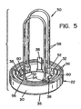
- FIGs. 4 and 5 an alternative lifting means is depicted for lifting the cartridge assembly 10 up by the bottom retainer ring 22, and is generally designated by the numeral 50.
- the interior 32 of the bottom retainer ring 22 has a plurality of inwardly extending bosses 52.
- a fillet 54 will provide a transitional area between each side of the boss 52 to the interior 32. It should be appreciated that there are an even number of bosses 52 disposed on the inferior 32, and while the preferred number of bosses is four, a minimum of two should suffice.
- each boss carries a hole 56.
- At least one strap or handle 58 is affixed to a boss via the hole 56 and is extended through the entire length of the aperture 18, As depicted in Fig. 5, a handle 58 comprising a single strap is looped through the aperture 18 and both ends are affixed within opposed holes 56.
- the length of each handle 58 is dependent upon the length of the filler cartridge assembly 10. ideally, the length of the handle 58 is such that a sufficient amount will extend out from the top retainer ring assembly 22 so as to provide an adequate length for manipulating the filter cartridge assembly 10.
- each handle 58 will be a flexible plastic rod with the necessary tensile strength for lifting the wet filter assembly 10.
- the diameter of the plastic rod is less than the diameter of the hole 56.
- the handle 58 could be a stranded or solid steel wire or other similar material. Each end of the handle 58 is inserted through the hole 56 and deformed to create a head 60 that has a diameter larger than the hole 56. Other methods of deforming the handle 58, such as tying a knot or crimping a lug thereon, may also be used. In order to prevent the handles 58 from slipping down, a plastic friction-fit bushing, stainless steel clip or the like (not shown), can be positioned immediately above the bosses 52, as will be appreciated by those skilled in the art.
- the handles 58 may be grasped to lift the filter cartridge assembly 10 out of the filter housing.
- this bottom lifting variation reduces the possibility of the bottom filter cell sticking to either the inlet or the outlet of the filler housing.
- the cartridge assembly 10 breaks away from the bottom filler cell, the likelihood of distributing the filtered material about the filter housing is greatly increased.
- lifting a cartridge assembly 10 by the bottom retaining ring 22 greatly increases the stability of the assembly during the lifting process.
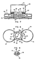
- a ring strap or handle generally designated by the numeral 80 is shown in Fig. 7.
- the top retainer ring 22 is configured as in the previous embodiments, however, a pair of diametrically opposed recesses 82 are provided on the exterior thereof.
- the recesses 82 are configured so as to receive the opposed ends 83 of a lifting handle 84.
- the lifting handle 84 may be inserted into and received by the recesses 82. Accordingly, the filter cartridge assembly 10 is lifted away from the inlet or outlet with which it is in cooperation.
- the material of the lifting handle 84 is made of a suitable material such as spring steel or plastic. In other words, the lifting handle 84 is made of a material flexible enough to be inserted into the recesses 82, yet strong enough to lift a wet filler cartridge assembly 10.
- the ring 22 is sufficiently flexible to allow the installation of handle ends 83 therein.
- the lifting strap can be rotated out of the way in order to accommodate assembly and closure of the cartridge or, it can be removed from the cartridge altogether, and re-inserted at the next instance the cartridge is to be removed from the housing.
- lifting means 90 comprises twin lifting straps 91 and a modified top retainer ring assembly 22.
- the latter is made with a plurality of tabs 92, extending radially outwardly from the outer surface 93 of retainer ring 22, each of which carries an aperture 94 for receipt of a pointed foot member 95.
- Foot members 95 extend perpendicularly from the opposed ends 96 of lifting straps 91 and are joined to the retainer ring 22 by engagement with the apertures 94.
- the material for the lifting straps 91 which are typically made of plastic, is rigid enough to support the weight of a wet filter cartridge assembly 10, while still allowing the straps 91 to be flexible for manipulation in conjunction with lifting the assembly out of the filter housing 28.
- the lifting straps 91 are mounted in a fashion to provide twin opposed ovals; however, it should be appreciated that the straps 91 may be configured in any other shape that is conducive to lifting a wet cartridge assembly 10.
- the straps 91 are shown as removably attached to the retainer ring 22, it is to be understood they could as well be integrally molded therewith and therefore no attempt has been made to depict such an embodiment.
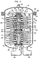
- the housing 28 is shown in cross-section. It includes a cylindrical body or sump 100 and removable cover 101, in order to gain access to the interior 102, of the housing 28.
- the cover 101 can be affixed in a variety of conventional manners, one being via an external circumferential clamp member 103, which engages matingly opposed circumferential flange members 104 and 105, from the body and cover members, respectively.
- the body member could include the top enclosure and be removably affixed to a base member and suitably clamped together.
- the base 106 of the housing 28 provides an inlet pipe 108 into the housing and an outlet pipe 109 for removal of filtrate, both of which are welded or otherwise sealingly engaged with respect to the housing 28.
- the outlet pipe 109 carries a rigid base plate 110, upon which the filter medium is supported within the housing.
- the base plate 110 provides a threaded bore for the receipt of a threaded shaft 111 which extends upwardly within the housing sufficiently to receive the number of filter cartridge assemblies for which the housing is designed (two as depicted in Figs. 10-13).
- the threaded shaft passes through a hollow rod 112 from which extend radially three or more centering fins 113.
- the outermost edges of fins 113 define a diameter corresponding to the inner diameter (at 32) of the retainer ring assemblies 22, which are, in turn, concentric with the central core 18 of each filter cell 12. Accordingly, as the cartridge assemblies 10 are stacked within the housing 28 they become properly aligned.
- baffle 114 Interposed between the base plate 110 and the lowermost retainer ring 22 from the lower filter cartridge assembly 10A is flow deflector plate or baffle 114 and the annular gasket 35 from the retainer ring assembly 22, the latter to effect sealing engagement between the central core 18 of the assembly 10A and the outlet pipe 109.
- the baffle is employed to disperse the inlet stream into the housing and protect the lowermost cell 12 from damage by the influent, which is typically fed in under pressure.
- the base plate 110 and baffle 114 are appropriately apertured at 116 to allow filtrate to exit from the assemblies 10A and 10B and into the outlet pipe 109.
- a follower tube 118 is placed within the uppermost retainer ring 22 and locking nut 119 is threaded onto the rod 111.
- Locking nut 119 provides a cage 120 which provides a bore 121 for receipt of the threaded rod 111.
- the cage provides an extension 122, which fits within the follower tube 118.
- a compression spring 123 is placed around the extension 122 and is fully compressed within an annular recess 124, when the head of cage 120 is in full contact with the top of the follower tube 118. Spring 123 maintains compression on the stack of cells, which can fluctuate in overall thickness (height) after the cells become wetted.
- An O-ring 125 is provided within the follower tube 118 sealing the cage extension 122 and follower tube 118 when the locking nut 119 has been secured in place to ensure that the filtered fluid within the central aperture 18 cannot escape into the housing interior 102, but must instead exit from the other end and into the outlet 109.
- Locking nut 119 and the accompanying components form a means for effecting a seal 126, at one end of the cell with which it communicates. Such seal is fluid tight and ensures that the fluid entering the central aperture(s) is directed toward the outlet.
- the housing 28 provides a a fitting 127 for a valve (not shown) to vent air from the sealed housing as fluid is admitted.
- each filter cartridge assembly 10 contains two retainer ring assemblies 22, one at the top of the cartridge, carried by the upper surface 16U, of the uppermost cell 12U in the cartridge, and one at the bottom of the cartridge, carried by the lower surface 16L, of the lowermost cell 12L in the cartridge.
- Each cartridge 10 within the housing will provide upper and lower retainer ring assemblies 22 in this fashion, irrespective of the number of cartridges actually employed e.g., one, two, three, four or more.
- the upper surface 16U of that cell 12 will be the upper surface of the cartridge 10U, carrying one of the retainer ring assemblies 22 and likewise, the lower surface 16L of that cell 12 will be the lower surface of the cartridge 10L, carrying the other of the retainer ring assemblies 22.
- the lifting means 50 of Figs. 4 and 5 is depicted.
- the strap 58 carried by the retainer ring 22 of lower cell assembly 10A passes upwardly through the central aperture 18 and extends into the aperture 18 of the upper cell assembly 10B.
- the strap 58 can be tucked within the aperture 18 of lower cell assembly 10A.
- the strap 58 carried by the retainer ring 22 of upper cell assembly 10B passes upwardly through the central aperture 18 and extends to the follower tube 118 or, it can be tucked within the aperture 18 of the assembly 10B.
- the housing When the housing is opened, the locking nut is removed, the first set of lifting straps are grasped and the upper cell assembly 10B can be removed. Next, the lifting straps of lower cell assembly 10A are grasped and it is then removed.
- the inlet 108 is first closed and the housing is drained so that no unfiltered fluids can contaminate the filtrate within outlet 109, before the seals are broken and removal of the assemblies commences.
- the procedure is reversed with the placement of two fresh assemblies 10, or whatever number the housing accommodates, and the locking nut is affixed, following which the housing is again closed and the fluid flow is resumed.
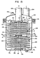
- Fig. 12 the lifting means 42, of Figs. 2 and 3 is depicted.
- Housing 128 provides a body or sump 129 and a removable cover 130, which is affixed via clamp 131, or other suitable means.
- the housing 128 provides a fitting 132 for a valve (not shown) for removal of air when the fluid is admitted, and a drain 133 for the removal of fluids during cartridge removal.
- this housing provides inlet and outlet 134, 135, respectively through the top cover, rather than at the base.
- a centering rod (not shown) is also provided as described hereinabove.
- the outlet 135 carries a compression plate 139 to which is mounted a baffle 140 to diffuse the inlet stream via 134.
- a threaded rod similar to rod 111 within housing 28 can be employed to provide the necessary compression by tightening an engaging nut, appropriately carried above the upper cartridge 10B.
- a spring-loaded mechanism (not shown) can be provided between the compression plate 139 and base plate 138 to effect sealing. As shown in Fig.
- the inlet can be located within the cover 130 at an appropriate dimension to provide sufficient compression of the assemblies as the cover is clamped in place, as will be appreciated by those skilled in the art.
- base plate 138 forms a means for effecting a seal 145, the functional equivalent of means 126, described hereinabove.
- the straps 41 carried by the retainer ring 22 of the lower cell assembly 10A, lay across the top of the uppermost filter cell 12U without interfering between the seal that needs to be formed between the lower and upper cell assemblies 10A and 10B.
- the lifting means provided by the present invention is unique, in part, because it does not interfere with the seal that must be formed between retainer ring assemblies to which the handles are provided in all embodiments other than Fig. 6.
- the lifting means does not interfere.
- the lifting means does not interfere.
- the lifting means does not interfere.
- the lifting means also does not interfere. In all instances, there is no risk of contamination between the filtrate stream, passing centrally through the cells and cartridge, and the unfiltered fluid within the housing, caused by the presence of the lifting means.
Landscapes
- Chemical & Material Sciences (AREA)
- Chemical Kinetics & Catalysis (AREA)
- Filtration Of Liquid (AREA)
- Separation Using Semi-Permeable Membranes (AREA)
- Apparatus Associated With Microorganisms And Enzymes (AREA)
- Control Of Motors That Do Not Use Commutators (AREA)
Claims (8)
- Herausnehmbare Filterpatrone (10) zur Anbringung in einem Gehäuse (28), das ein entfernbares Teil (101, 130), um Zugang zu dem Inneren (102, 136) des Gehäuses zu verschaffen, und einen Einlass (108, 134) und einen Auslass (109, 135) zu und aus seinem Inneren (102, 136) aufweist, wobei die Patrone wenigstens eine Filterzelle (12), durch die Flüssigkeit zur Filtration hindurchgeleitet wird, wobei die wenigstens eine Zelle einen offenen zentralen hindurchgehenden Kern (18) für die Durchleitung von Flüssigkeit getrennt von der Flüssigkeit innerhalb des Gehäuses und gegenüber- und auf Abstand zueinander liegende Scheiben aus Filtermedien (16) hat, die obere (16U) und untere (16L) Oberflächen definieren, die von dem mittleren Kern (18) radial nach außen verlaufen und an ihren äußeren Umfangsrändern (14) miteinander verbunden sind, wobei der zentrale Kern (18) gegenüberliegende erste und zweite Enden hat, und erste und zweite Halteringeinrichtungen (22), die von der Patrone offen zu und konzentrisch mit den gegenüberliegenden Enden des zentralen Kerns getragen werden, wodurch, wenn die Patrone in das Gehäuse eingesetzt wird, die erste Halteringeinrichtung an den Auslass des Gehäuses anschließt und die zweite Halteringeinrichtung mit einer Einrichtung (126) in Verbindung steht, die eine flüssigkeitsdichte Abdichtung über dem zentralen Kern (18) herstellt, um den Eintritt von ungefilterter Flüssigkeit in den Kern auszuschließen, und eine Hebeeinrichtung aufweist, um bei der Bewegung der Filterpatrone in das und aus dem Gehäuse zu helfen, dadurch gekennzeichnet, dass:die Hebeeinrichtungen (42, 50, 80, 90) mit einer der Halteringeinrichtungen (22) in Verbindung stehen, um das Anheben der Patrone zu erlauben, aber getrennt und entfernt von der Einrichtung (126) zum Herstellen einer flüssigkeitsdichten Dichtung sind.
- Filterpatrone nach Anspruch 1, wobei die Hebeeinrichtungen mit der ersten Halteringeinrichtung (22) in Verbindung stehen und wenigstens eine davon ausgehende Griffschlaufe (41, 58, 84, 91) aufweisen.
- Filterpatrone nach Anspruch 1 oder Anspruch 2, wobei die Patrone eine Vielzahl von Zellen aufweist und wenigstens ein Bandmittel (38) zum Zusammenhalten der Vielzahl von Zellen vorhanden ist, wobei der zentrale Kern (18) jeder Zelle offen zu und in Kommunikation mit den Kernen der anderen Zellen ist.
- Herausnehmbare Filterpatrone nach Anspruch 3, wobei das oder jedes Bandmittel (38) durch die zentralen Öffnungen der Zellen verläuft und an seinen beiden Enden mit der ersten und der zweiten Halteringeinrichtung (22) verbunden ist.
- Herausnehmbare Filterpatronenanordnung, die eine Vielzahl von Patronen (10A, 10B), jede nach einem der vorhergehenden Ansprüche, umfasst, wobei die erste Halteringeinrichtung (22) einer Patrone (10A) an die zweite Halteringeinrichtung (22) der benachbarten Patrone (10B) angrenzt, wodurch die aneinandergrenzenden Halteringeinrichtungen benachbarter Patronen eine Dichtung für die Durchleitung von Flüssigkeit durch die zentralen Kerne der Patronen bewirken.
- Filterpatronenanordnung nach Anspruch 5, wobei die zweite Halteringeinrichtung (22) der zweiten Patrone (10B) mit Mitteln (126) zum Bewirken einer Dichtung an einem Ende des durch die Zelle gebildeten zentralen Kerns gegenüber der ersten Halteringeinrichtung kommuniziert und der zentrale Kern darin eintretende Flüssigkeit durch den Auslass leitet.
- Filterpatronenanordnung nach Anspruch 5 oder Anspruch 6, die weiter wenigsten ein Bandmittel (38) zum Verbinden der Vielzahl von Zellen jeder Patrone aufweist, wobei die zentralen Kerne der Zellen jeder Patrone (10A, 10B) offen zu und in Kommunikation mit den Kernen der Zellen beider Patronen sind.
- Verfahren zum Einbau und zur Entnahme einer Filterpatrone (10) vom Zellentyp, die in einem Filtergehäuse (28) mit einem abnehmbaren Teil (101, 130), um Zugang zu dem Inneren des Gehäuses zu gewähren, und einem Einlass (108) und einem Auslass (134) zu und aus dessen Inneren angeordnet ist, wobei wenigstens eine Filterpatronenanordnung (10), durch die Flüssigkeiten zum Filtern geleitet werden, bereitgestellt wird, wobei die Patronenanordnung eine Vielzahl von Filterzellen (12) bereitstellt, wobei jede Zelle einen zentralen Kern (18) für den Durchgang von Flüssigkeit getrennt von der Flüssigkeit innerhalb des Gehäuses, gegenüberliegende Scheiben aus Filtermedien (16), die Abstand zueinander haben und obere (16U) und untere (16L) Oberflächen definieren, die von der zentralen Bohrung radial nach außen verlaufen und an ihren äußeren Umfangsrändern (16) miteinander verbunden sind, aufweist, wobei die zentralen Kerne (18) der Zellen aneinandergrenzend aufeinander folgend liegen, um gegenüberliegende erste und zweite Enden zu haben, und wobei erste und zweite Halteringeinrichtungen (22) vorhanden sind, die von der Filterpatronenanordnung (10) getragen werden und die offen zu und konzentrisch mit den gegenüberliegenden Enden des zentralen Kerns sind, wodurch, wenn die Patrone in ein Gehäuse eingebaut ist, die erste Halteringeinrichtung an den Auslass (109, 135) des Gehäuses angrenzt und die zweite Halteringeinrichtung mit den Mitteln (126) zum Herstellen einer flüssigkeitsdichten Dichtung über den zentralen Kern (18), um den Eintritt ungefilterter Flüssigkeit in den Kern zu verhindern, in Verbindung steht, und wobei die Patrone eine Hebeeinrichtung zum Unterstützen des Bewegens der Filterpatrone in das und aus dem Gehäuse aufweist, gekennzeichnet durch die Schritte:Vorbereitung des Gehäuses durch Abnehmen des Deckels davon,Anwenden einer Hebekraft auf die Hebeeinrichtungen (42, 50, 80, 90), die dazu ausgelegt sind, direkt mit einer der Halteringeinrichtungen (22) in Verbindung zu stehen, aber getrennt und gesondert von den Mitteln (126) zum Bewirken einer Dichtung über den Kern der Patrone sind, so dass die Patrone dadurch in das oder aus dem Gehäuse gehoben wird, wobei die zweite Halteringeinrichtung eine Dichtung mit den Mitteln (126) zum Herstellen einer Dichtung über den Kern der Patrone herstellt oder unterbricht, wie erforderlich, undBefestigen des abnehmbaren Teils (101, 130) an dem Filtergehäuse.
Applications Claiming Priority (3)
| Application Number | Priority Date | Filing Date | Title |
|---|---|---|---|
| US317911 | 1981-11-03 | ||
| US08/317,911 US5482624A (en) | 1994-10-04 | 1994-10-04 | Filter cells providing lifting means and related methods |
| PCT/US1995/012891 WO1996011736A1 (en) | 1994-10-04 | 1995-10-03 | Filter cells providing lifting means and related methods |
Publications (3)
| Publication Number | Publication Date |
|---|---|
| EP0784497A1 EP0784497A1 (de) | 1997-07-23 |
| EP0784497A4 EP0784497A4 (de) | 1998-09-02 |
| EP0784497B1 true EP0784497B1 (de) | 2003-02-26 |
Family
ID=23235789
Family Applications (1)
| Application Number | Title | Priority Date | Filing Date |
|---|---|---|---|
| EP95937376A Expired - Lifetime EP0784497B1 (de) | 1994-10-04 | 1995-10-03 | Aufhebemittel verschaffende filterzellen und verwandte methoden |
Country Status (7)
| Country | Link |
|---|---|
| US (2) | US5482624A (de) |
| EP (1) | EP0784497B1 (de) |
| JP (1) | JPH10507404A (de) |
| AU (1) | AU686477B2 (de) |
| CA (1) | CA2201752A1 (de) |
| DE (1) | DE69529757T2 (de) |
| WO (1) | WO1996011736A1 (de) |
Families Citing this family (33)
| Publication number | Priority date | Publication date | Assignee | Title |
|---|---|---|---|---|
| US5482624A (en) * | 1994-10-04 | 1996-01-09 | Cuno Incorporated | Filter cells providing lifting means and related methods |
| FR2766383B1 (fr) * | 1997-07-22 | 1999-10-08 | Fleetguard | Cartouche de filtrage munie de moyens permettant de faciliter son extraction de la cuve d'un filtre |
| GB9718858D0 (en) * | 1997-09-06 | 1997-11-12 | Harlent Limited | Filter Cartridges and Filter Cells |
| DE19744572A1 (de) * | 1997-10-09 | 1999-04-15 | Schenk Filterbau Gmbh | Filtermodul |
| DE19744574B4 (de) | 1997-10-09 | 2005-12-22 | Schenk-Filterbau Gmbh | Filtermodul |
| US5958226A (en) * | 1997-12-29 | 1999-09-28 | Fleischmann; Charles R. | Storm drain filter with removable debris tray |
| US6139253A (en) * | 1998-08-12 | 2000-10-31 | Cuno, Inc. | Lifting device for transporting disk stacks |
| DE19927662C1 (de) * | 1999-06-17 | 2000-10-05 | Seitz Filter Werke | Hebevorrichtung für Filtermodule |
| DE29915781U1 (de) * | 1999-09-08 | 2000-01-05 | Seitz-Filter-Werke GmbH, 55543 Bad Kreuznach | Filtermodul mit Spannelementen |
| DE19949613C2 (de) * | 1999-10-14 | 2002-06-27 | Steinecker Maschf Anton | Manipulator für scheibenförmige Filter- oder Siebelemente |
| EP1313537B1 (de) * | 2000-08-29 | 2006-11-29 | 3M Innovative Properties Company | Mittelpfostensystem zum fördern von linsenförmiger filtereinsatzvorrichtung |
| GB2374556A (en) * | 2001-03-21 | 2002-10-23 | Beda Technology Ltd | Disc Filtration Device |
| JP2004535915A (ja) * | 2001-04-18 | 2004-12-02 | キュノ、インコーポレーテッド | レンチキュラフィルタカートリッジ用ハンドル |
| US6632355B2 (en) | 2001-07-30 | 2003-10-14 | Pentapure Incorporated | Low spillage replaceable water filter assembly |
| AT411430B (de) * | 2002-06-19 | 2004-01-26 | Andritz Ag Maschf | Filter- oder sortierscheibe und verfahren zur herstellung |
| US20040178137A1 (en) * | 2003-03-10 | 2004-09-16 | Koichi Itoh | Reinforcement structures for multi-cell filter cartridge |
| US6955696B1 (en) * | 2003-07-31 | 2005-10-18 | Filtration Group, Inc. | Filter frame and assembly |
| BRPI0413926A (pt) * | 2003-08-27 | 2006-10-24 | 3M Innovative Properties Co | sistema de filtração de água, coletor de água, método de instalar um sistema de filtração de água e conector para conectar tubulação |
| CN1856450A (zh) * | 2003-09-23 | 2006-11-01 | 3M创新有限公司 | 减压水过滤系统 |
| US20050133463A1 (en) * | 2003-10-17 | 2005-06-23 | Kirchner Richard A. | Water filter manifold with integral valve |
| AU2004288182A1 (en) * | 2003-10-28 | 2005-05-19 | 3M Innovative Properties Company | Improved designs for filtration systems within appliances |
| AU2005207860A1 (en) * | 2004-01-20 | 2005-08-11 | 3M Innovative Properties Company | Water dispenser with water filter for a refrigerator |
| EP1629876A1 (de) * | 2004-08-27 | 2006-03-01 | Filtrox AG | Filtermodulaufbau mit Zusammenhalte-Elementen |
| WO2008073818A2 (en) * | 2006-12-08 | 2008-06-19 | Ohio University | Improved exfiltration device |
| US20080257801A1 (en) * | 2007-04-23 | 2008-10-23 | Yael Neeman | Device For Filtering Solid Particles For Liquids Containing Such Particles |
| EP2190554B1 (de) * | 2007-09-07 | 2013-01-09 | Donaldson Company, Inc. | Luftfilteranordnung |
| US20090255880A1 (en) * | 2008-04-14 | 2009-10-15 | Pritchard Scott J | Single use sanitary filter assembly |
| KR101014159B1 (ko) * | 2010-04-19 | 2011-02-14 | 케이원에코텍 주식회사 | 원형 여과판 및 이 여과판이 구성된 여과장치 |
| US9017554B2 (en) | 2010-08-27 | 2015-04-28 | Xylem Water Solutions Zelienople Llc | Handle for underdrain |
| US9043997B2 (en) * | 2012-02-22 | 2015-06-02 | Spectrum Brands, Inc. | Filter assembly and methods for external filter for an aquarium |
| WO2016179594A1 (en) * | 2015-05-07 | 2016-11-10 | Avitus Orthopaedics, Inc. | Systems and methods for bone and tissue harvesting |
| CN109126253B (zh) * | 2018-09-01 | 2020-11-06 | 华迪钢业集团有限公司 | 单面中空不锈钢过滤板 |
| US12220657B2 (en) * | 2021-04-30 | 2025-02-11 | Pall Corporation | Filter disk segments |
Family Cites Families (22)
| Publication number | Priority date | Publication date | Assignee | Title |
|---|---|---|---|---|
| US2353433A (en) * | 1941-11-17 | 1944-07-11 | Joseph F Auberschek | Fluid filter |
| US2757802A (en) * | 1952-01-10 | 1956-08-07 | J A Zurn Mfg Co | Stacked discs strainer assembly |
| US2731155A (en) * | 1953-03-27 | 1956-01-17 | Fram Corp | Filter cartridge pull-out device |
| US2781914A (en) * | 1954-06-01 | 1957-02-19 | Gen Motors Corp | Sock type filters |
| GB933178A (en) * | 1961-01-30 | 1963-08-08 | British Filters Ltd | Improvements in and relating to liquid filters |
| US3666107A (en) * | 1970-09-17 | 1972-05-30 | Food Research & Equipment Co | Filter unit |
| CA1044537A (en) * | 1973-05-09 | 1978-12-19 | Amf Incorporated | Filter medium and process |
| DE2628535A1 (de) * | 1975-06-30 | 1977-01-27 | Gen Electric | Filteranordnung |
| US4309247A (en) * | 1976-03-15 | 1982-01-05 | Amf Incorporated | Filter and method of making same |
| CA1148872A (en) * | 1979-04-06 | 1983-06-28 | Eugene A. Ostreicher | Filter with inorganic cationic colloidal silica |
| US4617128A (en) * | 1979-09-10 | 1986-10-14 | Amf Inc. | Particulate filter aid, filter bed and process |
| US4347208A (en) * | 1981-04-13 | 1982-08-31 | Amf Incorporated | Method of making filter cell having sealed periphery |
| US4361486A (en) * | 1981-04-28 | 1982-11-30 | Amf Incorporated | Filter media, method for oxidizing and removing soluble iron, method for removing and inactivating microorganisms, and particulate filter aid |
| US4669167A (en) * | 1985-10-29 | 1987-06-02 | Filter Specialists, Inc. | Method of removing filter bag |
| US4881313A (en) * | 1988-02-03 | 1989-11-21 | Cuno, Incorporated | Method of forming a cell filter with an exposed surface |
| US4921606A (en) * | 1989-06-30 | 1990-05-01 | Mechanical Manufacturing Corporation | Seamless filter bags with a removable, refusable ring |
| US5045194A (en) * | 1990-04-02 | 1991-09-03 | Gaf Chemicals Corporation | Filter apparatus having a bag with handles |
| US5217610A (en) * | 1992-03-18 | 1993-06-08 | Elite Commercial & Industrial, Inc. | Apparatus for removing metal particles from a liquid and method for making same |
| US5246581A (en) * | 1992-09-30 | 1993-09-21 | Mechanical Manufacturing Corporation | Seamless filter bags with integral sealing means |
| US5328606A (en) * | 1993-04-08 | 1994-07-12 | Travis Warren | Spin on oil filter with extendible handle |
| US5417855A (en) * | 1994-02-15 | 1995-05-23 | Isp Investments Inc. | Filter bag subassembly |
| US5482624A (en) * | 1994-10-04 | 1996-01-09 | Cuno Incorporated | Filter cells providing lifting means and related methods |
-
1994
- 1994-10-04 US US08/317,911 patent/US5482624A/en not_active Expired - Lifetime
-
1995
- 1995-10-03 CA CA002201752A patent/CA2201752A1/en not_active Abandoned
- 1995-10-03 DE DE69529757T patent/DE69529757T2/de not_active Expired - Lifetime
- 1995-10-03 EP EP95937376A patent/EP0784497B1/de not_active Expired - Lifetime
- 1995-10-03 JP JP8513331A patent/JPH10507404A/ja not_active Ceased
- 1995-10-03 AU AU39502/95A patent/AU686477B2/en not_active Ceased
- 1995-10-03 WO PCT/US1995/012891 patent/WO1996011736A1/en not_active Ceased
- 1995-10-03 US US08/538,729 patent/US5607584A/en not_active Expired - Lifetime
Also Published As
| Publication number | Publication date |
|---|---|
| AU3950295A (en) | 1996-05-06 |
| EP0784497A4 (de) | 1998-09-02 |
| WO1996011736A1 (en) | 1996-04-25 |
| JPH10507404A (ja) | 1998-07-21 |
| DE69529757D1 (de) | 2003-04-03 |
| CA2201752A1 (en) | 1996-04-25 |
| DE69529757T2 (de) | 2003-10-16 |
| US5607584A (en) | 1997-03-04 |
| US5482624A (en) | 1996-01-09 |
| EP0784497A1 (de) | 1997-07-23 |
| AU686477B2 (en) | 1998-02-05 |
Similar Documents
| Publication | Publication Date | Title |
|---|---|---|
| US5607584A (en) | Filter cells providing lifting means and related methods | |
| US5601710A (en) | Filtering apparatus of water purifier | |
| US5151180A (en) | Radial and axial flow stage filter device | |
| US6585892B2 (en) | Concentrically-arranged flexible media and support basket with second stage cartridge filter | |
| US4081379A (en) | Filter bag arrangement for a pressure vessel and method of manufacture thereof | |
| CA1127552A (en) | Multiple plate filter apparatus | |
| US4402828A (en) | Pressure filter vessel | |
| US6030531A (en) | Filter element assembly | |
| EP0095465B1 (de) | Ölfilterabdichtungsmembran | |
| CA2482412A1 (en) | Filter device with a segmented design | |
| JPH0319928Y2 (de) | ||
| JPH03114502A (ja) | ストレーナ組立体 | |
| EP1313537B1 (de) | Mittelpfostensystem zum fördern von linsenförmiger filtereinsatzvorrichtung | |
| JPH10328507A (ja) | 流体フィルタ | |
| AU2001291277A1 (en) | Center post system for transporting lenticular filter cartridge assembly | |
| JP4875270B2 (ja) | フィルタエレメント組立体 | |
| DE3638859A1 (de) | Filtereinsatzsystem | |
| WO2007021686A2 (en) | Exchangeable double casted cartridge filter | |
| CN217418372U (zh) | 一种净水器滤芯 | |
| US20250303327A1 (en) | Strainer | |
| US4789472A (en) | Adsorption apparatus | |
| JPH038350Y2 (de) | ||
| JPH072006Y2 (ja) | 放電加工液浄化用フィルターエレメント | |
| KR100439852B1 (ko) | 공기밸브용 여과망 | |
| JPH08323113A (ja) | 使い捨て型多段濾過装置 |
Legal Events
| Date | Code | Title | Description |
|---|---|---|---|
| PUAI | Public reference made under article 153(3) epc to a published international application that has entered the european phase |
Free format text: ORIGINAL CODE: 0009012 |
|
| 17P | Request for examination filed |
Effective date: 19970428 |
|
| AK | Designated contracting states |
Kind code of ref document: A1 Designated state(s): DE FR GB IT |
|
| A4 | Supplementary search report drawn up and despatched |
Effective date: 19980713 |
|
| AK | Designated contracting states |
Kind code of ref document: A4 Designated state(s): DE FR GB IT |
|
| 17Q | First examination report despatched |
Effective date: 19991125 |
|
| GRAG | Despatch of communication of intention to grant |
Free format text: ORIGINAL CODE: EPIDOS AGRA |
|
| GRAG | Despatch of communication of intention to grant |
Free format text: ORIGINAL CODE: EPIDOS AGRA |
|
| GRAH | Despatch of communication of intention to grant a patent |
Free format text: ORIGINAL CODE: EPIDOS IGRA |
|
| GRAH | Despatch of communication of intention to grant a patent |
Free format text: ORIGINAL CODE: EPIDOS IGRA |
|
| GRAA | (expected) grant |
Free format text: ORIGINAL CODE: 0009210 |
|
| AK | Designated contracting states |
Designated state(s): DE FR GB IT |
|
| PG25 | Lapsed in a contracting state [announced via postgrant information from national office to epo] |
Ref country code: IT Free format text: LAPSE BECAUSE OF FAILURE TO SUBMIT A TRANSLATION OF THE DESCRIPTION OR TO PAY THE FEE WITHIN THE PRESCRIBED TIME-LIMIT;WARNING: LAPSES OF ITALIAN PATENTS WITH EFFECTIVE DATE BEFORE 2007 MAY HAVE OCCURRED AT ANY TIME BEFORE 2007. THE CORRECT EFFECTIVE DATE MAY BE DIFFERENT FROM THE ONE RECORDED. Effective date: 20030226 |
|
| REG | Reference to a national code |
Ref country code: GB Ref legal event code: FG4D |
|
| REF | Corresponds to: |
Ref document number: 69529757 Country of ref document: DE Date of ref document: 20030403 Kind code of ref document: P |
|
| ET | Fr: translation filed | ||
| PLBE | No opposition filed within time limit |
Free format text: ORIGINAL CODE: 0009261 |
|
| STAA | Information on the status of an ep patent application or granted ep patent |
Free format text: STATUS: NO OPPOSITION FILED WITHIN TIME LIMIT |
|
| 26N | No opposition filed |
Effective date: 20031127 |
|
| REG | Reference to a national code |
Ref country code: GB Ref legal event code: 732E |
|
| REG | Reference to a national code |
Ref country code: FR Ref legal event code: TP |
|
| PGFP | Annual fee paid to national office [announced via postgrant information from national office to epo] |
Ref country code: GB Payment date: 20071029 Year of fee payment: 13 Ref country code: FR Payment date: 20071017 Year of fee payment: 13 |
|
| GBPC | Gb: european patent ceased through non-payment of renewal fee |
Effective date: 20081003 |
|
| REG | Reference to a national code |
Ref country code: FR Ref legal event code: ST Effective date: 20090630 |
|
| PG25 | Lapsed in a contracting state [announced via postgrant information from national office to epo] |
Ref country code: FR Free format text: LAPSE BECAUSE OF NON-PAYMENT OF DUE FEES Effective date: 20081031 |
|
| PG25 | Lapsed in a contracting state [announced via postgrant information from national office to epo] |
Ref country code: GB Free format text: LAPSE BECAUSE OF NON-PAYMENT OF DUE FEES Effective date: 20081003 |
|
| PGFP | Annual fee paid to national office [announced via postgrant information from national office to epo] |
Ref country code: DE Payment date: 20100929 Year of fee payment: 16 |
|
| PG25 | Lapsed in a contracting state [announced via postgrant information from national office to epo] |
Ref country code: DE Free format text: LAPSE BECAUSE OF NON-PAYMENT OF DUE FEES Effective date: 20120501 |
|
| REG | Reference to a national code |
Ref country code: DE Ref legal event code: R119 Ref document number: 69529757 Country of ref document: DE Effective date: 20120501 |