EP0786583A2 - Combinaison d'une vanne rotative et distributeur - Google Patents
Combinaison d'une vanne rotative et distributeur Download PDFInfo
- Publication number
- EP0786583A2 EP0786583A2 EP97300419A EP97300419A EP0786583A2 EP 0786583 A2 EP0786583 A2 EP 0786583A2 EP 97300419 A EP97300419 A EP 97300419A EP 97300419 A EP97300419 A EP 97300419A EP 0786583 A2 EP0786583 A2 EP 0786583A2
- Authority
- EP
- European Patent Office
- Prior art keywords
- air
- valve
- rotary valve
- motor
- exhaust
- Prior art date
- Legal status (The legal status is an assumption and is not a legal conclusion. Google has not performed a legal analysis and makes no representation as to the accuracy of the status listed.)
- Withdrawn
Links
- 230000000694 effects Effects 0.000 claims description 10
- 230000002441 reversible effect Effects 0.000 claims description 5
- 238000004891 communication Methods 0.000 claims description 2
- LYKJEJVAXSGWAJ-UHFFFAOYSA-N compactone Natural products CC1(C)CCCC2(C)C1CC(=O)C3(O)CC(C)(CCC23)C=C LYKJEJVAXSGWAJ-UHFFFAOYSA-N 0.000 abstract 1
- 239000012530 fluid Substances 0.000 abstract 1
- 238000013022 venting Methods 0.000 description 2
- 229910000906 Bronze Inorganic materials 0.000 description 1
- 239000010974 bronze Substances 0.000 description 1
- 238000010276 construction Methods 0.000 description 1
- KUNSUQLRTQLHQQ-UHFFFAOYSA-N copper tin Chemical compound [Cu].[Sn] KUNSUQLRTQLHQQ-UHFFFAOYSA-N 0.000 description 1
- 238000007789 sealing Methods 0.000 description 1
Images
Classifications
-
- F—MECHANICAL ENGINEERING; LIGHTING; HEATING; WEAPONS; BLASTING
- F01—MACHINES OR ENGINES IN GENERAL; ENGINE PLANTS IN GENERAL; STEAM ENGINES
- F01L—CYCLICALLY OPERATING VALVES FOR MACHINES OR ENGINES
- F01L33/00—Rotary or oscillatory slide valve-gear or valve arrangements, specially adapted for machines or engines with variable fluid distribution
- F01L33/02—Rotary or oscillatory slide valve-gear or valve arrangements, specially adapted for machines or engines with variable fluid distribution rotary
-
- F—MECHANICAL ENGINEERING; LIGHTING; HEATING; WEAPONS; BLASTING
- F01—MACHINES OR ENGINES IN GENERAL; ENGINE PLANTS IN GENERAL; STEAM ENGINES
- F01B—MACHINES OR ENGINES, IN GENERAL OR OF POSITIVE-DISPLACEMENT TYPE, e.g. STEAM ENGINES
- F01B1/00—Reciprocating-piston machines or engines characterised by number or relative disposition of cylinders or by being built-up from separate cylinder-crankcase elements
- F01B1/06—Reciprocating-piston machines or engines characterised by number or relative disposition of cylinders or by being built-up from separate cylinder-crankcase elements with cylinders in star or fan arrangement
-
- Y—GENERAL TAGGING OF NEW TECHNOLOGICAL DEVELOPMENTS; GENERAL TAGGING OF CROSS-SECTIONAL TECHNOLOGIES SPANNING OVER SEVERAL SECTIONS OF THE IPC; TECHNICAL SUBJECTS COVERED BY FORMER USPC CROSS-REFERENCE ART COLLECTIONS [XRACs] AND DIGESTS
- Y10—TECHNICAL SUBJECTS COVERED BY FORMER USPC
- Y10T—TECHNICAL SUBJECTS COVERED BY FORMER US CLASSIFICATION
- Y10T137/00—Fluid handling
- Y10T137/5109—Convertible
- Y10T137/5196—Unit orientable in a single location between plural positions
-
- Y—GENERAL TAGGING OF NEW TECHNOLOGICAL DEVELOPMENTS; GENERAL TAGGING OF CROSS-SECTIONAL TECHNOLOGIES SPANNING OVER SEVERAL SECTIONS OF THE IPC; TECHNICAL SUBJECTS COVERED BY FORMER USPC CROSS-REFERENCE ART COLLECTIONS [XRACs] AND DIGESTS
- Y10—TECHNICAL SUBJECTS COVERED BY FORMER USPC
- Y10T—TECHNICAL SUBJECTS COVERED BY FORMER US CLASSIFICATION
- Y10T137/00—Fluid handling
- Y10T137/5109—Convertible
- Y10T137/5196—Unit orientable in a single location between plural positions
- Y10T137/524—Reversible stop and vent or waste
-
- Y—GENERAL TAGGING OF NEW TECHNOLOGICAL DEVELOPMENTS; GENERAL TAGGING OF CROSS-SECTIONAL TECHNOLOGIES SPANNING OVER SEVERAL SECTIONS OF THE IPC; TECHNICAL SUBJECTS COVERED BY FORMER USPC CROSS-REFERENCE ART COLLECTIONS [XRACs] AND DIGESTS
- Y10—TECHNICAL SUBJECTS COVERED BY FORMER USPC
- Y10T—TECHNICAL SUBJECTS COVERED BY FORMER US CLASSIFICATION
- Y10T137/00—Fluid handling
- Y10T137/8593—Systems
- Y10T137/86389—Programmer or timer
- Y10T137/86405—Repeating cycle
Definitions
- This invention relates to air motor valves and more particularly to a combination rotary supply and directional control valve for hoist motors and the like.
- the rotary valve is mounted at the back of the motor and is driven by pins that engage the crank shaft. This requires exact alignment, a separate rotary valve housing and a separate directional control valve and housing.
- a rotary distribution valve and directional spool valve combination for use with an air motor operated hoist or the like comprising a rotary valve disposed in a valve first body bore and driven in rotation by an air motor receiving a distributed supply of air from said rotary valve in sequential order to operate said motor; characterised in that a spool valve is disposed in a valve second body bore for reciprocation from a forward position supplying air to said rotary valve to effect forward rotation of said motor and to a rearward position supplying air to said rotary valve to effect reverse rotation of said motor; and said first body bore and said second body bore are interconnected by a first passageway and a second passageway alternately supplying and exhausting air from said spool valve to a first face end of said rotary valve and to a second face end of said rotary valve to effect distribution and exhaust of air to and from said motor.
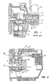
- a typical piston air motor is shown in cross-section with the rotary valve 1 housed in a separate housing 2 at the rear.
- the rotary valve runs in a bronze sleeve 3 and is driven by pins 4 which are accurately aligned and engaged in a crank 5.
- Air passages 6 and 7 communicate with cylinder ports 10 and with a directional control valve 8 mounted on the rotary valve housing 2.
- the air passage 6 Depending on which direction that the air motor is running, if the air passage 6 is supplying air to drive a piston from the top of its stroke to the bottom, the air passage 7 will, at the same time, be venting air from an opposing piston as it goes from the bottom of its stroke to the top. This venting cycle is called the secondary exhaust cycle.
- a primary exhaust cycle is usually carried out on piston air motors in which the compressed air that is in the cylinder at the instant that the piston reaches the bottom of its stroke, is vented directly through the rotary valve and out through an exhaust passage 9 at the back of the motor, by-passing the directional control valve completely.
- the primary exhaust cycle improves the operating efficiency of the air motor by reducing the volume of air that must be pushed by the pistons back through the directional control valve.
- the arrows on passages 6 and 7 indicate that the supply and exhaust air must reverse direction completely when passing through the rotary valve.
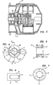
- a piston air motor is shown in cross-section with a simplified rotary valve 21 mounted on a crankshaft 22.
- the crankshaft is carried on bearings 23 and 24 pressed into a motor body 25.
- the bearings 23 and 24 have the same outside diameter as the rotary valve 21 allowing it to have a close running fit in a housing bore 35.
- Figure 3 shows cylinder ports C1 and C2 aligning and communicating with annular cavities S1 and T1 in the rotary valve 21.
- Figures 4 to 7 show the rotary valve 21 in detail, where the annular cavities S1 and T1 are separated by diametral lands M and L.
- An axial annular slot 26 passes through face A and connects with the cavity S1 and an axial annular slot 27 passes through face B and connects with the cavity T1.
- the cavities S1 and T1 also have similar radial slots 28 (best seen in Figure 6) and 29 (best seen in Figure 4) allowing communication with cylinder ports C1 in sequence as the rotary valve rotates in the motor housing
- the radial slots 28 and 29 effect the timing of air distribution and exhaust from the cylinder ports C1 and C2 or any opposed pair of cylinder ports (C3, C4, etc. - not shown).
- the radial slot 29 may be provided with an angle of advance D1 and angle of supply E, and an angle of shut-off F as determined relative to motor port C1 and top dead centre of the motor piston (not shown) corresponding to C1 (assuming counterclockwise rotation) and different but corresponding angles for radial slot 28 (exhaust timing). This permits air supply and exhaust timing to be selected for optimum motor performance.
- Timing pin 38 is located on the mid-point between face A and B to retain proper axial orientation on crankshaft 22.
- Figure 2 shows a cross-section through the motor body that includes a section through the directional control valve in which a spool 30 is carried in a bore 36 in a sleeve 31 which is pressed into the motor body.
- a pneumatic actuator 37 through a control rod 38
- inlet supply air at port 'W' is directed to port 'Y' which supplies pressurised air to the right hand face A and cavity S1 through the slot 26 of the rotary valve 21 which, as it rotates, communicates this pressurised air to each cylinder in sequence.
- cavity T1 connected to port 'X' via the slot 27, is vented to exhaust through channel 'X1' in the motor body.
- Stationary seal rings 33 and 34 are provided with a tight fit in the housing bore 35 and a relatively loose but sealing fit on the crankshaft 22. This permits the seal rings to remain stationary in normal operation.
- Each seal is formed by a disc having a shaft bore pressed into said rotary valve bore, the disc carrying the seals.
- a significant improvement in air flow between ports 'X' and 'Y' and cavities S1 and T1 is achieved by placing the entry and exit slots 26 and 27 on faces A and B respectively of the rotary valve. This allows a more direct air passage requiring only a single ninety degree turn to communicate with cylinder ports C1 and C2, as indicated by the arrows in Figure 2.
Landscapes
- Engineering & Computer Science (AREA)
- Mechanical Engineering (AREA)
- General Engineering & Computer Science (AREA)
- Multiple-Way Valves (AREA)
- Fluid-Driven Valves (AREA)
- Sliding Valves (AREA)
Applications Claiming Priority (2)
| Application Number | Priority Date | Filing Date | Title |
|---|---|---|---|
| US08/590,235 US5775199A (en) | 1996-01-23 | 1996-01-23 | Rotary valve and directional valve combination |
| US590235 | 1996-01-23 |
Publications (2)
| Publication Number | Publication Date |
|---|---|
| EP0786583A2 true EP0786583A2 (fr) | 1997-07-30 |
| EP0786583A3 EP0786583A3 (fr) | 1998-07-29 |
Family
ID=24361414
Family Applications (1)
| Application Number | Title | Priority Date | Filing Date |
|---|---|---|---|
| EP97300419A Withdrawn EP0786583A3 (fr) | 1996-01-23 | 1997-01-23 | Combinaison d'une vanne rotative et distributeur |
Country Status (4)
| Country | Link |
|---|---|
| US (1) | US5775199A (fr) |
| EP (1) | EP0786583A3 (fr) |
| JP (1) | JPH09196196A (fr) |
| KR (1) | KR970059552A (fr) |
Cited By (1)
| Publication number | Priority date | Publication date | Assignee | Title |
|---|---|---|---|---|
| CN104454735A (zh) * | 2014-12-05 | 2015-03-25 | 天津市瑞芬机电技术开发有限公司 | 一种气动葫芦的三位五通气动换向阀 |
Families Citing this family (2)
| Publication number | Priority date | Publication date | Assignee | Title |
|---|---|---|---|---|
| WO2006075981A1 (fr) * | 2005-01-13 | 2006-07-20 | Sumitomo Heavy Industries, Ltd | Tiroir cylindrique hybride destine a un tube a impulsions multipoint |
| FR2934033B1 (fr) * | 2008-07-15 | 2010-09-03 | Fives Stein | Dispositif de pilotage de bruleurs regeneratifs. |
Family Cites Families (7)
| Publication number | Priority date | Publication date | Assignee | Title |
|---|---|---|---|---|
| US666690A (en) * | 1899-02-06 | 1901-01-29 | Q & C Company | Engine. |
| US2397594A (en) * | 1945-01-06 | 1946-04-02 | J D Buchanan | Hydraulic motor or pump |
| CH266197A (de) * | 1945-10-03 | 1950-01-15 | Skf Svenska Kullagerfab Ab | Pneumatischer Motor. |
| GB1012672A (en) * | 1960-12-21 | 1965-12-08 | Chamberlain Ind Ltd | Improvements in hydraulic motors |
| US3090363A (en) * | 1961-07-18 | 1963-05-21 | Paul M Stuver | Fluid motor |
| JPS56983A (en) * | 1979-06-15 | 1981-01-08 | Kawasaki Steel Co | Method of detecting slag in molten metal flow |
| JPH04295182A (ja) * | 1991-03-25 | 1992-10-20 | Myotoku Kk | 流体圧を利用した回転装置 |
-
1996
- 1996-01-23 US US08/590,235 patent/US5775199A/en not_active Expired - Lifetime
-
1997
- 1997-01-22 KR KR1019970001796A patent/KR970059552A/ko not_active Withdrawn
- 1997-01-23 JP JP9009892A patent/JPH09196196A/ja active Pending
- 1997-01-23 EP EP97300419A patent/EP0786583A3/fr not_active Withdrawn
Non-Patent Citations (1)
| Title |
|---|
| None |
Cited By (1)
| Publication number | Priority date | Publication date | Assignee | Title |
|---|---|---|---|---|
| CN104454735A (zh) * | 2014-12-05 | 2015-03-25 | 天津市瑞芬机电技术开发有限公司 | 一种气动葫芦的三位五通气动换向阀 |
Also Published As
| Publication number | Publication date |
|---|---|
| JPH09196196A (ja) | 1997-07-29 |
| KR970059552A (ko) | 1997-08-12 |
| US5775199A (en) | 1998-07-07 |
| EP0786583A3 (fr) | 1998-07-29 |
Similar Documents
| Publication | Publication Date | Title |
|---|---|---|
| KR100307279B1 (ko) | 내연기관의축을상대회전시키기위한상대회전장치와이장치의작동방법 | |
| US4854825A (en) | Multi-stage vacuum pump | |
| US3175510A (en) | Variable displacement pump | |
| KR940009527A (ko) | 왕복운동형 압축기 | |
| US4807519A (en) | Piston machine with changeable displacement | |
| CA2254336A1 (fr) | Actuateur hydraulique electrique a surete integree | |
| KR940018561A (ko) | 왕복동형 압축기 | |
| FI64840C (fi) | Hydraulisk motor | |
| US3855903A (en) | Engines, pumps and motors | |
| US6105541A (en) | Free piston internal combustion engine with rotating piston | |
| US6544013B2 (en) | Oil pump apparatus | |
| EP0786583A2 (fr) | Combinaison d'une vanne rotative et distributeur | |
| KR20030047729A (ko) | 고정용량형 피스톤식 압축기에 있어서의 윤활구조 | |
| US5137438A (en) | Multiple speed fluid motor | |
| GB2237333A (en) | Hydraulic unit with scavenge valve | |
| US5979501A (en) | Fluid distributing apparatus for piston-type hydraulic motors or pumps | |
| US6460333B2 (en) | Hydraulic pressure transformer | |
| US8052401B2 (en) | Double-acting radial piston hydraulic apparatus | |
| US6793471B2 (en) | Fluid machine | |
| GB1602202A (en) | Rotary-cylinder reciprocating-piston machines | |
| US4589328A (en) | Rotary piston engine with reciprocating cylinders having sealing and friction reducing members | |
| EP0891470B1 (fr) | Moteur a piston rotatif | |
| US4511313A (en) | Compression capacity control apparatus for swash plate compressor | |
| US3307454A (en) | Rotary piston machines and cylinder housings | |
| US5127376A (en) | Rotary valve shaft |
Legal Events
| Date | Code | Title | Description |
|---|---|---|---|
| PUAI | Public reference made under article 153(3) epc to a published international application that has entered the european phase |
Free format text: ORIGINAL CODE: 0009012 |
|
| AK | Designated contracting states |
Kind code of ref document: A2 Designated state(s): DE FR GB IT SE |
|
| PUAL | Search report despatched |
Free format text: ORIGINAL CODE: 0009013 |
|
| AK | Designated contracting states |
Kind code of ref document: A3 Designated state(s): DE FR GB IT SE |
|
| 17P | Request for examination filed |
Effective date: 19990109 |
|
| STAA | Information on the status of an ep patent application or granted ep patent |
Free format text: STATUS: THE APPLICATION HAS BEEN WITHDRAWN |
|
| 18W | Application withdrawn |
Withdrawal date: 20010820 |