EP0786706B1 - Toner cartridge and drum cartridge for receiving the toner cartridge therein - Google Patents
Toner cartridge and drum cartridge for receiving the toner cartridge therein Download PDFInfo
- Publication number
- EP0786706B1 EP0786706B1 EP97100974A EP97100974A EP0786706B1 EP 0786706 B1 EP0786706 B1 EP 0786706B1 EP 97100974 A EP97100974 A EP 97100974A EP 97100974 A EP97100974 A EP 97100974A EP 0786706 B1 EP0786706 B1 EP 0786706B1
- Authority
- EP
- European Patent Office
- Prior art keywords
- pipe
- cartridge
- toner cartridge
- inner pipe
- outer pipe
- Prior art date
- Legal status (The legal status is an assumption and is not a legal conclusion. Google has not performed a legal analysis and makes no representation as to the accuracy of the status listed.)
- Expired - Lifetime
Links
- 238000007789 sealing Methods 0.000 claims description 25
- 238000010276 construction Methods 0.000 claims description 13
- 230000007423 decrease Effects 0.000 claims description 3
- 230000005484 gravity Effects 0.000 claims description 3
- 239000012780 transparent material Substances 0.000 claims description 3
- 238000012423 maintenance Methods 0.000 claims 1
- 230000000063 preceeding effect Effects 0.000 claims 1
- 238000007599 discharging Methods 0.000 description 8
- 230000000630 rising effect Effects 0.000 description 3
- 238000003780 insertion Methods 0.000 description 2
- 230000037431 insertion Effects 0.000 description 2
- 238000000034 method Methods 0.000 description 2
- 238000012986 modification Methods 0.000 description 2
- 230000004048 modification Effects 0.000 description 2
- 238000003756 stirring Methods 0.000 description 2
- JOYRKODLDBILNP-UHFFFAOYSA-N Ethyl urethane Chemical compound CCOC(N)=O JOYRKODLDBILNP-UHFFFAOYSA-N 0.000 description 1
- 238000004140 cleaning Methods 0.000 description 1
- 238000010586 diagram Methods 0.000 description 1
- 230000000694 effects Effects 0.000 description 1
- 239000000463 material Substances 0.000 description 1
- 230000002035 prolonged effect Effects 0.000 description 1
- 239000012858 resilient material Substances 0.000 description 1
- 239000003566 sealing material Substances 0.000 description 1
Images








Classifications
-
- G—PHYSICS
- G03—PHOTOGRAPHY; CINEMATOGRAPHY; ANALOGOUS TECHNIQUES USING WAVES OTHER THAN OPTICAL WAVES; ELECTROGRAPHY; HOLOGRAPHY
- G03G—ELECTROGRAPHY; ELECTROPHOTOGRAPHY; MAGNETOGRAPHY
- G03G15/00—Apparatus for electrographic processes using a charge pattern
- G03G15/06—Apparatus for electrographic processes using a charge pattern for developing
- G03G15/08—Apparatus for electrographic processes using a charge pattern for developing using a solid developer, e.g. powder developer
- G03G15/0822—Arrangements for preparing, mixing, supplying or dispensing developer
- G03G15/0865—Arrangements for supplying new developer
- G03G15/0867—Arrangements for supplying new developer cylindrical developer cartridges, e.g. toner bottles for the developer replenishing opening
- G03G15/087—Developer cartridges having a longitudinal rotational axis, around which at least one part is rotated when mounting or using the cartridge
- G03G15/0872—Developer cartridges having a longitudinal rotational axis, around which at least one part is rotated when mounting or using the cartridge the developer cartridges being generally horizontally mounted parallel to its longitudinal rotational axis
-
- G—PHYSICS
- G03—PHOTOGRAPHY; CINEMATOGRAPHY; ANALOGOUS TECHNIQUES USING WAVES OTHER THAN OPTICAL WAVES; ELECTROGRAPHY; HOLOGRAPHY
- G03G—ELECTROGRAPHY; ELECTROPHOTOGRAPHY; MAGNETOGRAPHY
- G03G15/00—Apparatus for electrographic processes using a charge pattern
- G03G15/06—Apparatus for electrographic processes using a charge pattern for developing
- G03G15/08—Apparatus for electrographic processes using a charge pattern for developing using a solid developer, e.g. powder developer
- G03G15/0822—Arrangements for preparing, mixing, supplying or dispensing developer
- G03G15/0848—Arrangements for testing or measuring developer properties or quality, e.g. charge, size, flowability
- G03G15/0856—Detection or control means for the developer level
-
- G—PHYSICS
- G03—PHOTOGRAPHY; CINEMATOGRAPHY; ANALOGOUS TECHNIQUES USING WAVES OTHER THAN OPTICAL WAVES; ELECTROGRAPHY; HOLOGRAPHY
- G03G—ELECTROGRAPHY; ELECTROPHOTOGRAPHY; MAGNETOGRAPHY
- G03G2215/00—Apparatus for electrophotographic processes
- G03G2215/06—Developing structures, details
- G03G2215/066—Toner cartridge or other attachable and detachable container for supplying developer material to replace the used material
- G03G2215/0663—Toner cartridge or other attachable and detachable container for supplying developer material to replace the used material having a longitudinal rotational axis, around which at least one part is rotated when mounting or using the cartridge
- G03G2215/0665—Generally horizontally mounting of said toner cartridge parallel to its longitudinal rotational axis
-
- G—PHYSICS
- G03—PHOTOGRAPHY; CINEMATOGRAPHY; ANALOGOUS TECHNIQUES USING WAVES OTHER THAN OPTICAL WAVES; ELECTROGRAPHY; HOLOGRAPHY
- G03G—ELECTROGRAPHY; ELECTROPHOTOGRAPHY; MAGNETOGRAPHY
- G03G2215/00—Apparatus for electrophotographic processes
- G03G2215/06—Developing structures, details
- G03G2215/066—Toner cartridge or other attachable and detachable container for supplying developer material to replace the used material
- G03G2215/0663—Toner cartridge or other attachable and detachable container for supplying developer material to replace the used material having a longitudinal rotational axis, around which at least one part is rotated when mounting or using the cartridge
- G03G2215/0675—Generally cylindrical container shape having two ends
-
- G—PHYSICS
- G03—PHOTOGRAPHY; CINEMATOGRAPHY; ANALOGOUS TECHNIQUES USING WAVES OTHER THAN OPTICAL WAVES; ELECTROGRAPHY; HOLOGRAPHY
- G03G—ELECTROGRAPHY; ELECTROPHOTOGRAPHY; MAGNETOGRAPHY
- G03G2215/00—Apparatus for electrophotographic processes
- G03G2215/08—Details of powder developing device not concerning the development directly
- G03G2215/0888—Arrangements for detecting toner level or concentration in the developing device
- G03G2215/0891—Optical detection
- G03G2215/0894—Optical detection through a light transmissive window in the developer container wall
-
- Y—GENERAL TAGGING OF NEW TECHNOLOGICAL DEVELOPMENTS; GENERAL TAGGING OF CROSS-SECTIONAL TECHNOLOGIES SPANNING OVER SEVERAL SECTIONS OF THE IPC; TECHNICAL SUBJECTS COVERED BY FORMER USPC CROSS-REFERENCE ART COLLECTIONS [XRACs] AND DIGESTS
- Y10—TECHNICAL SUBJECTS COVERED BY FORMER USPC
- Y10S—TECHNICAL SUBJECTS COVERED BY FORMER USPC CROSS-REFERENCE ART COLLECTIONS [XRACs] AND DIGESTS
- Y10S222/00—Dispensing
- Y10S222/01—Xerography
Definitions
- the present invention relates to a toner cartridge structure and a drum cartridge structure for receiving the toner cartridge therein.
- FIG. 11 is a perspective view of the prior art apparatus
- Fig. 12 is a partial cutaway view as seen along the lines A-A of Fig. 11,
- Fig. 13 is a longitudinal cross-sectional view.
- a toner cartridge subassembly 31 in the figures includes an outer pipe 32, an inner pipe 37, and caps 41.
- the outer pipe 32 takes the form of a pipe, and has openings 33 at longitudinal opposite ends thereof and a plurality of cutouts'34 formed in each opening.
- the outer pipe 32 is formed with a plurality of openings 35 therein aligned longitudinally thereof. The opening 35 is for discharging toner therethrough.
- the outer pipe 32 has a rib 36 that extends circumferentially thereof to define the openings 35.
- the inner pipe 37 in the form of a hollow cylinder slidably fits into the outer pipe 32.
- the inner pipe 37 has openings 38 at longitudinal opposite ends, concentric with respect to the outer pipe 32.
- the inner pipe 37 is formed with a plurality of openings 39 therein through which toner in the inner pipe 37 is discharged when the openings 39 are aligned with the openings 35.
- the inner pipe 37 has two ribs 40 extending circumferentially thereof, which ribs 40 are positioned such that ribs 40 define three openings 39, side by side, with one in the middle having an opening area twice as large as the other two adjacent ones.
- the caps 41 and 41a fit to the corresponding openings 38, respectively.
- the cap 41a is formed with a toner filling hole 42 therein.
- the cap 41 is formed with a cross-shaped groove 56 as shown in Fig. 14B, which is not shown in Fig. 13 ['or simplicity of explanation.
- a cap 43 fits into the toner-filling hole 42.
- the gap between the outer pipe 32 and the inner pipe 37 is sealed by means of a sealing material, not shown. Likewise, the gap between the caps 41 and the longitudinal ends of the inner pipe 37 are sealed.
- the inner pipe 37 is slidably rotated relative to the outer pipe 32 till the openings 39 are aligned with the openings 35, thereby discharging toner in the inner pipe 37 through the aligned openings.
- Slidably rotating the inner pipe 37 in the reverse direction relative to the outer pipe 32 causes the openings 35 and 39 to move out of alignment with each other, thereby closing the opening 39 in the inner pipe 37 by means of the outer pipe 32.
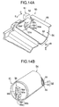
- Figs. 14A and 14B are perspective views of an essential part of the prior art apparatus, Fig. 14A showing only a left one of the two structures provided at the left and right ends of a drum cartridge 50 that receives the toner cartridge 54, and Fig. 14B showing only a left one of the two structures provided at the left and right ends of the toner cartridge 54.
- a cartridge-receiving space 64 of the drum cartridge 50 includes a rotor 51 that is supported by the chassis 66 means of a hinged support and is rotatable relative to the chassis 66.
- the rotor 51 has a lever 52 and a cross-shaped projection 53 which are formed in one piece with the rotor 51.
- a projection 53 includes a long main projection 53a and a short sub projection 53b, which is perpendicular to the main projection 53a and formed in the middle of the main projection 53a.
- the main projection 53a has a first side 53c on its right hand side and a second side 53d on its left side hand.
- the sub projection 53b has a first sub projection 53e on its right hand side and a second sub projection 53f on its left hand side.
- the cap 41 is provided with a cross-shaped groove 56 and loosely fits over the projection 53 of the rotor 51.
- the groove 56 includes a main groove 56a and a sub groove 56b which is perpendicular to the main groove 56a at the middle of the main groove 56a.
- the main groove 56a has a first side wall 56c on its left hand side and a second side wall 56d on its right hand side.
- the sub groove 56b has a first sub groove 56e on its left hand side and a second sub groove 56f on its right hand side.
- Figs. 15A-15H illustrate the mounting and dismounting operations of the prior art cartridge 54.
- the rotor 51 is depicted in solid line, and the cap 41 is depicted in dot-dash line.
- the lever 52 is operated to rotate the rotor 51 in the direction illustrated by arrow C as shown in Fig. 15A till the lever 52 abuts a stopper, not shown, and is then slightly operated in the reverse direction.
- the rotor 51 now takes up a cartridge-setting position where the cartridge 54 is to be placed in the cartridge-receiving space 64 of the drum cartridge (Fig. 15B).
- the cartridge 54 While being held parallel to the cartridge-receiving space 64, the cartridge 54 is lowered so that the projection 53 advances into the groove 56 of the cap 41 (Fig. 15B). The projection 53 is at an angle preventing the cartridge 54 from completely being inserted into the cartridge-receiving space 64 (Fig. 15B). Then, the cartridge 54 is further inserted into the cartridge-receiving space 64 while operating the lever 52 relative to the cap 41 slightly in the direction illustrated by arrow C as shown in Fig. 15C. The projection 53 is now in parallel to the groove 56 so that the cartridge 54 enters completely into the cartridge-receiving space 64.
- the bottom of the outer pipe 32 is in close contact with a sealing member 60 of the cartridge-receiving space 64 and is exerted an upward force by the sealing member 60.
- the lever 52 is operated to rotate the rotor 51 in the direction opposite to arrow C (Fig. 15D). While being rotated, the first sub projection 53e engages the sub groove 56e of the groove 56 which is pushed upwardly by the sealing member 60. The upward force is still acting on the cap 41 while the sub projection 53e engages the sealing member 60.
- the rotor 51 again reaches the cartridge-setting position (Fig. 15D)
- the projection 53 becomes oblique to the groove 56 so that the first side 53c abuts the side wall 56c. This completes the mounting of the cartridge 54 into the cartridge-receiving space 64.
- the rotor 51 is rotated in the direction illustrated by arrow B till the the rotor 51 abuts a stopper, not shown, as shown in Fig. 15E.
- the rotation of the rotor 51 is transmitted via the projection 53 and groove 56 to the cap 41, so that the cap 41 is also rotated in the direction illustrated by arrow B.
- the inner pipe 37 slidably rotates in the outer pipe 32.
- the cartridge 54 tends to rise from the cartridge-receiving space 64 due to angular moment.
- the engagement of the first sub projection 53e with the first sub groove 56e prevents the cartridge 54 from rising.
- the sealing member 60 secured to the rotor 51 as shown in Fig.
- the lever 52 is operated to rotate the rotor 51 in the direction illustrated by arrow C as shown in Fig. 15F.
- the rotor 51 alone rotates slightly relative to the cap 41 due to the loose engagement between the projection 53 and the groove 56, and a further rotation of the rotor 51 causes the second projection 53f to engage the second groove 56f.
- the rotor 51 is still further rotated as shown in Fig. 15G in the direction indicated by arrow C till the rotor 51 abuts a stopper, not shown. In this situation, the cartridge 54 tends to rise from the cartridge-mounting space 64 due to angular moment.
- the sealing member 60 in Fig. 14 rotates together with the rotor 51 in the direction illustrated by arrow C to close the opening 61 in the bottom of the cartridge-mounting space 64.
- the inner pipe 37 rotates relative to the outer pipe 32 in the direction illustrated by arrow C so that the openings 35 are completely out of alignment with the opening 39. This is the "closed cartridge" condition.
- the aforementioned prior art cartridge is disadvantageous in that the number of parts is large, sealing means are required at both longitudinal ends, and the assembly operation is rather complex.
- the user when discharging the toner, the user must simultaneously rotate the lever 52 of the rotor 51 at both ends of the drum cartridge using both hands.
- the document EP-A-0 435 596 describes a toner cartridge in form of a cylinder, which is composed of an outer cylinder and an inner cylinder, which is coaxial and concentric to the outer cylinder.
- the document EP-A-0 597 507 describes a toner cartridge in form of an outer cylinder, in which an inner cylinder is contained. A cover is provided on the inner cylinder and this cover is concentric to the inner cylinder.
- the document US-A-3 356 248 describes a toner cartridge composed of a hollow cylindrical sleeve and a cylindrical core or liner.
- the document EP-A-0 744 671 describes a toner cartridge composed of an inner cylindrical member and an outer cylindrical member rotatable relative to and concentrically mounted around the inner cylindrical member. The cylindrical members are covered with cover elements.
- the document EP-A-0 733 483 describes a toner cartridge which comprises a container and a cover member. An object of the invention is to provide a toner cartridge which is simple in construction and easy to assemble.
- Another object of the invention is to provide a toner cartridge where toner can be discharged by operating a knob with only one hand.
- Still another object of the invention is to provide a toner cartridge/drum cartridge construction where the toner cartridge can be easily mounted to the drum cartridge.
- a toner cartridge according to the present invention includes an outer pipe (1), inner pipe (2) inserted into the outer pipe (1), and cap (5) fitted over the inner pipe (2).
- the outer pipe (1) is of a long pipe shape and is formed with a plurality of first openings (1b) therein aligned longitudinally thereof.
- the inner pipe is of a long pipe shape and has first and second longitudinal ends opposing each other.
- the pipe body of the inner pipe (2) is formed with a plurality of second openings (2b) therein aligned longitudinally thereof.
- the first end of the inner pipe (2) has a toner-filling opening (2c) extending longitudinally, and a first flange (1a) eccentric with respect to the pipe body, while the second end has a knob (4) that closes the longitudinal end of the pipe body and abuts the outer pipe.
- the first openings (1b) are not aligned with the second openings (2b) when the inner pipe (2) is at a first rotational position and are aligned when the inner pipe (1) is at a second rotational position.
- a sealing member (3) is mounted to the inner pipe (2), encircling the second openings (2b). The sealing member (3) not only seals the gap between the outer pipe (1) and the inner pipe (2) but also holds the inner pipe (1) eccentric with respect to the outer pipe (1).
- the sealing member (3) has third openings (3b) which are in alignment with the second openings (2b) in the inner pipe (2) when the inner pipe (2) is assembled into the outer pipe (1).
- the outer pipe (1) is provided with at least one flange (1a) which radially outwardly extends from the outer surface of the outer pipe (1) and longitudinally extends along the outer pipe (1).
- the flange (1a) has a plurality of ribs (1d) on one side thereof.
- the toner-filling opening (2c) has the same diameter as that of the pipe body of the inner pipe (2).
- the second openings (2b) are open in the direction opposite to the direction in which the first flange (1a) of the inner pipe (2) is eccentric with respect to the pipe body.
- the knob (4) is of a generally disc shape and has a part of the outer surface tapered such that the thickness of the knob (4) decreases with the radial distance from the center of the disc shape.
- the knob (4) has an outer circumferential surface concentric with respect to the outer pipe (1). On the outer circumferential surface is provided a mark, which is aligned with one of the flanges (1a) of the outer pipe (1) for a proper rotational position of the inner pipe relative to the outer pipe (1).
- In the outer circumferential surface is provided with an arcuate groove (4f) along the circumferential surface.
- the arcuate groove (4f) loosely fits over at least one projection formed on the bottom surface of a drum cartridge into which the tone cartridge is mounted, so that the rotation of the knob (4) is properly guided by the arcuate groove (4f) and the projection fitted therein
- the knob (4) has a radially projecting lever (4g).
- the lever (4g) has a first arrow (4h) and a second arrow (4i) formed thereon.
- the first farrow (4h) indicates the rotational direction of the lever when the toner cartridge is is to be dismounted from the drum cartridge.
- the second arrow (4i) indicates the rotational direction of the lever when the inner pipe is to be rotated to the second rotational position to dump the toner after the toner cartridge has been received in the drum cartridge.
- the cap (5) has a conically tapered surface on a radially outer part of the top surface thereof.
- the cap (5) may be made of a transparent material and graduated with, for example, in the form of a plurality of lines so that the amount of the toner in the cartridge may be inspected.
- the drum cartridge has a receiving portion (16) in the form of a hollow semi-cylinder for receiving the toner cartridge.
- the receiving portion (16) has first and second side walls opposing each other at longitudinal ends thereof.
- the receiving portion (16) opens upwardly and extends longitudinally.
- the receiving portion (16) has opposed first and second side walls at opposed ends.
- Fig. 1 is a perspective view of an outer pipe of a toner cartridge of the invention.
- Fig. 2A is a perspective view of an inner pipe of the toner cartridge of the invention.
- Fig. 2B is a perspective view of a sealing member.
- Fig. 3 illustrates the inner pipe inserted into the outer pipe.
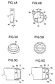
- Figs. 4A-4B illustrate the side of a knob.
- Fig. 5A is a perspective view of a cap.
- Fig. 5B illustrates a modification of the cap.
- Fig. 5C is a cross-sectional side view of the cap fitted over the inner pipe taken along lines V-V in Fig. 6.
- Fig. 5D is a cross-sectional view of the cap having a recess.
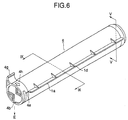
- Fig. 6 is a perspective view of the assembled toner cartridge of the invention.
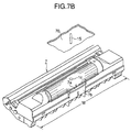
- Fig. 7A illustrates the toner cartridge received in a drum cartridge.
- Fig. 7B illustrates the knob fully rotated from the position in Fig. 7A.
- Fig. 7C illustrates a drum cartridge of the invention in detail.
- Fig. 8A illustrates the essential part of the drum cartridge shown in Figs. 7A and 7B.
- Fig. 8B illustrates the procedure for mounting the toner cartridge into the drum cartridge.
- Fig. 8C illustrates a modification of the drum cartridge in Fig. 8A.
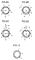
- Figs. 9A-9B illustrate the relative rotational positions of the inner pipe and outer pipe.
- Figs. 9C-9D illustrate the relative rotational positions of modified inner an outer pipes.
- Fig. 10 illustrates an inner pipe concentric with respect to an outer pipe.
- Fig. 11 is a perspective view showing the prior art.
- Fig. 12 is a perspective view, partly cut away, as seen in the direction of arrow A-A.
- Fig. 13 is a longitudinal cross-sectional view of a prior art toner cartridge.
- Fig. 14A is a perspective view of an essential part of a prior art drum cartridge.
- Fig. 14B is a perspective view of an essential part of the prior art toner cartridge.
- Figs. 15A-15H are illustrative diagrams showing the mounting and dismounting operations of the prior art toner cartridge.
- Fig. 1 is a perspective view of an outer pipe 1 of a toner cartridge of the invention.
- the outer pipe 1 is generally of a cylindrical shape having a small thickness, and opens at longitudinal opposed ends.
- the outer pipe 1 has two flanges 1a that prevent the toner cartridge 6 from rotating when mounting the toner cartridge 6 into the drum cartridge 7, and three openings 1b through which the toner is dumped into the drum cartridge 7.
- the flanges 1a are provided at diametrically opposed positions and extend longitudinally of the outer pipe 1. On one side of each flange are provided a plurality of ribs 1d along the outer pipe as shown in Fig. 6.
- the openings 1b are aligned longitudinally of the sleeve.
- Fig. 2A is a perspective view of an inner pipe 2 of the toner cartridge of the invention.
- the inner pipe 2 is of a generally cylindrical shape having a small thickness and a diameter smaller than the inner diameter of the outer pipe 1.
- the inner pipe 2 has a toner-filling opening 2c that opens at a first longitudinal end thereof, and a knob 4 that closes the inner pipe at a second end opposing the first end.
- the inner pipe 2 has two flanges 2a that are eccentric with respect to the pipe body of the inner pipe and has a slightly larger outer diameter than that of the pipe body. The two flanges define a circumferential groove 2d therebetween.
- the maximum outer diameter of the cap 5 is as large as that of the outer pipe 1.
- three openings 2b that are aligned longitudinally of the inner pipe and are open in a direction opposite to a direction in which the flanges 2a are eccentric with respect to the pipe body.
- the outer circumferential surface of the knob 4 has a diameter large than the outer diameter of the inner pipe but the same as the inner diameter of the outer pipe 1.
- the openings immediately adjacent the opposed longitudinal ends are arranged not too far from the longitudinal ends, preferably 12 mm, equal to a width of a later described sealing member 3, so that toner is not left in the inner pipe after the toner has been dumped into the drum cartridge 7.
- the knob 4 is formed with a circumferential groove 4f therein along the circumferential surface, and an arrow 4h indicative of the direction in which the knob 4 is to be rotated.
- the groove 4f guides the rotation of the knob 4 when the toner is discharged from the toner cartridge 6 into the drum cartridge 7.
- the knob 4 has a mark 4e in the form of a low projection arranged in the middle of the opening 2b as shown in Fig. 2B.
- Figs. 4A-4B illustrate the knob 4.
- the knob 4 has a radially projecting lever 4g, which has an arrow 4i provided thereon indicative of the rotational direction of the knob 4.
- the knob 4 is formed with a circumferential wall 4d that extends along the circumference of the disc shape of the knob 4.
- the circumferential wall 4d has a cutout 4b therein.
- L-shaped ribs 4a and 4c are symmetrical with respect to the center of the disc shaped knob 4 and are inscribed in the circumferential wall 4d.
- the straight portions of the rib 4a are parallel to the straight portions of the rib 4c and are a predetermined distance L apart as shown in Fig. 4B.
- the rib 4a is immediately adjacent to the cutout 4b. As shown in Fig.
- the knob 4 has a tapered or chamfered part 4j at an angle ⁇ on the side thereof such that the thickness of the knob 4 decreases toward the cutout 4b.
- the taper 4j facilitates insertion of the toner cartridge 6 into the drum cartridge 7.
- Fig. 2B is a perspective view showing a sealing member 3.
- the sealing member 3 is formed of a resiliently deformable material such as urethane, sponge, felt, or the like, and has a thickness slightly larger than the gap between the inner and outer pipes, as shown in Figs. 9A-9D, between the inner pipe 2 and the outer pipe 1.
- the openings 3b in the sealing member 3 are slightly larger than the openings 2b.
- the sealing member 3 is bonded to the inner pipe 2 by means of, for example, a double sided bonding tape is such a way that the openings 3b are aligned with the openings 2b.
- the sealing member 3 seals the gap between the inner pipe 2 and the outer pipe 1 upon assembling the inner pipe 2 into the outer pipe 1, preventing the toner from leaking from the inner pipe 2.
- the sealing member 3 causes the inner pipe 2 to be eccentric with respect to the outer pipe and frictionally holds the inner pipe 2 in position relative to the outer pipe 1.
- Fig. 3 illustrates the inner pipe 2 inserted into the outer pipe 1.
- the inner pipe 2 is rotated so that the mark 4e on the knob 4 is in alignment with the flange 1a of the outer pipe 1 where the openings 2b are completely closed by the outer pipe 1 and the openings 1b are completely closed by the inner pipe 2, thereby properly sealing the gap between the inner pipe and the outer pipe.
- the side of the knob 4 serves as a stopper against the axial movement of the outer pipe 1 relative to the inner pipe 2.
- Fig. 6 is a perspective view of the completely assembled toner cartridge with the inner pipe filled with the toner. Since the maximum outer diameter of the cap 5 is the same as that of the outer pipe 1, the cap 5 serves as a stopper against the axial movement of the outer pipe 1 once the cap 5 has been fitted over the toner filling opening 21c. Thus, the inner pipe 2 is frictionally rotatable relative to the outer pipe 1 but is unable to move axially relative to the outer pipe.
- Fig. 9A is a cross-sectional view taken along lines IX-IX of Fig. 6.
- the pipe body of the inner pipe 2 is eccentric with respect to the outer pipe 1 so that the the outer circumferential surface of the inner pipe 2 diametrically opposite to the openings 2b is urged against the inner wall of the outer pipe 1 upon completion of assembly.
- the flange 2a eccentric with respect to the pipe body of the inner pipe 2 is concentric with respect to the outer pipe 1.
- a toner-accommodating space can have a larger inner diameter in an inner pipe eccentric with respect to the outer pipe shown in Fig. 9A-9B than in an inner pipe concentric with respect to an outer pipe as shown in Fig. 10.
- the resultant larger inner diameter provides a larger toner-accommodating space.
- the urging force exerted on the inner pipe 2 by the outer pipe via the sealing member 3 can cause the inner pipe to deflect in the middle thereof.
- the inner pipe 2 receives a force from the outer pipe 1 via the sealing member 3 and another force directly from the outer pipe 1. These two forces are equal in magnitude and opposite in direction, preventing the inner pipe 2 from deflecting in one direction during prolonged storage of the toner cartridge 6.
- Fig. 5C is a cross-sectional side view of the cap fitted over the inner pipe 2, taken along lines V-V in Fig. 6.
- the cap 5 is formed of a resilient material such as rubber.
- the cap 5 has an inwardly projecting annular projection 5b which fits into a groove 2d in the inner pipe 2 with a snap action when forcibly fitted over the toner-filling opening 2c.
- the outer diameter of the cap 5 is the same as that of the outer pipe 1.
- the cap 5 has a conically tapered surface on a radially outer part of the top surface thereof, the tapered surface facilitating the mounting of the toner cartridge 6 into the drum cartridge 7.
- the drum cartridge 7 has a receiving portion 16 in the form of a hollow semi-cylinder having a semi-circular cross section for receiving the toner cartridge 6 therein.
- the receiving portion 16 opens upwardly and extends longitudinally.
- the receiving portion 16 has first and second side walls 17a and 17b located at opposed longitudinal ends.
- the first side wall 17a is formed with a vertically extending projection 10 thereon which is a predetermined distance apart from the bottom of the receiving portion leaving a small space 10a under the projection 10.
- the width T of the projection 10 is selected to be smaller than the distance L between the ribs 4a and 4c.
- On the bottom of the receiving portion 16 near the projection 10 are provided two upward projections 12b.
- Fig. 7C shows the drum cartridge 50 in detail.
- a toner receiving space 81 is immediately below the receiving portion 16.
- the toner receiving space 81 houses a toner supplying roller 83 and a stirring bar 82 which is rotated to stir the toner so that the toner is distributed evenly in the toner receiving space 81.
- the developing roller 85 is rotated in contact with the toner supplying roller 83.
- a developing blade 90 operates to deposit the toner layer of a predetermined thickness on the developing roller 85.
- the developing roller 85 rotates in contact with the photosensitive drum 89 to deposit the toner layer on the photosensitive drum 89.
- a charging roller 87 and cleaning roller 88 are rotated in contact with the photosensitive drum 89.
- a recording medium such as paper travels below the drum cartridge 50 in the direction of arrow P.
- An LED head 86 enters the drum cartridge 50 through a hole 84 and opposes the photosensitive drum 89. The LED head 86 selectively illuminates the surface of the photosensitive drum 89 in accordance with the information received from the main part of the electrography recording apparatus, not shown, so as to form an electrostatic latent image on the surface of the photosensitive drum.
- the toner cartridge 6 is held in a position as shown in Fig. 6 with respect to the drum cartridge 7.
- the toner cartridge 6 is inserted in the direction of arrow D into the receiving portion of the drum cartridge 7 so that the cap 5 enters under the projection 11.
- the toner cartridge 6 is gently inclined about the cap 5 in the direction of arrow E so that the the projection 10 of the drum cartridge 7 enters the gap between the ribs 4a and 4c through the cutout 4b.
- the taper 4j of the knob 4 facilitates the smooth entering of the rib 4 into the drum cartridge 7.
- the two flanges 1a of the outer pipe 1 are seated on the longitudinally extending edges of the receiving portion 16, and the projections 12h on the bottom of the receiving portion 16 loosely fits into the arcuate groove 4f in the knob 4.
- the toner cartridge is comfortably seated in the drum cartridge 7 as shown in Fig. 7A.
- the inner pipe 2 is in a positional relation as shown in Fig. 9A with the outer pipe 1.
- the projections 12b loosely fitted into the groove 4f serve to smoothly guide the knob 4 when the knob 4 is rotated in order to discharge the toner.
- the step 5c of the cap 5 engages the projection 11 and the outer surface of the tone cartridge 6 is flush with the projection 11.
- operating the lever 4g to rotate the knob 4 in the direction illustrated by the arrow 4h causes the circumferential wall 4d to enter the space 10a under the projection 10, preventing the toner cartridge 6 from rising up.
- the rotation of the knob 4 causes the inner pipe 2 to frictionally rotate relative to the outer pipe 1.
- the two flanges 1a seated on the drum cartridge 7 hold the outer pipe 1 in position, preventing the outer pipe 1 from rotating together with the inner pipe 2 when dumping the toner into the drum cartridge.
- the inner pipe 2 is in a positional relation as shown in Fig. 9B with the outer pipe 1.
- the knob 4 With the knob 4 at this rotational position, the openings 1b of the outer pipe 1, openings 2b of the inner pipe 2 and openings 16a of the receiving portion of the drum cartridge 7 are aligned with one another so that the toner is dumped from the inner pipe 2 into the drum cartridge 7.
- the invention provides a simple mounting operation of the toner cartridge.
- the toner cartridge/drum cartridge construction is such that the inner pipe 2 stops rotation thereof at a position where the openings 2b are in alignment with the openings 1b of the outer pipe 1. This construction ensures discharge of toner from the toner cartridge 6 into the drum cartridge 7.
- the resilient cap 5 having the same outer diameter as the outer pipe 1 is fitted over the flanges 2a with a snap action and prevents pull-out of the outer pipe 1 from the inner pipe 2. This construction reduces the number of parts and ensures sealing effect at the toner-filling opening.
- the cap 5 may be made of a transparent material and graduated as shown in Fig. 5B with a plurality of lines so that the amount of toner contained in the toner cartridge 6 can be visually inspected.
- the toner cartridge 6 may be constructed to have a recess 2e in the inner pipe 2 and a hole 1c in the outer pipe 1 as shown in Figs. 9C-9D so that the the recess 2e is in alignment with the hole 1c only when the the knob 4 is fully rotated to the position shown in Fig. 7B.
- a pin 15 may be provided on the lid 70 of the electrography recording apparatus at such a position that the pin 15 enters the recess 2e through the hole 1c when the lid 70 is closed after discharge of toner into the drum cartridge 7. This construction prevents the user from inadvertently closing the lid 70 with the knob 4 left between the two extreme ends of rotation thereof.
- the drum cartridge 7 contains toner therein and therefore is preferably held horizontal when taking out from the electrography recording apparatus.
- the center of gravity of the drum cartridge 7 is not always at an equal distance M/2 from left and right ends thereof and therefore the drum cartridge may be preferably provided with an arrow 7b indicative of the center of'gravity at which the user should hold the drum cartridge 7 when lifting it from the electrography recording apparatus.
- the side wall 17b may be provided with a projection 13 as shown in Fig. 8C, and the cap 5 may be provided with a recess 5d as shown in Fig. 5D into which the projection loosely extends when the toner cartridge 6 is mounted into the receiving portion 16. The projection ensures rotation of the inner pipe 2 when discharging toner.
Landscapes
- Physics & Mathematics (AREA)
- General Physics & Mathematics (AREA)
- Dry Development In Electrophotography (AREA)
- Electrophotography Configuration And Component (AREA)
Applications Claiming Priority (2)
| Application Number | Priority Date | Filing Date | Title |
|---|---|---|---|
| US592926 | 1996-01-29 | ||
| US08/592,926 US5722019A (en) | 1996-01-29 | 1996-01-29 | Toner cartridge and drum cartridge for receiving the toner cartridge therein |
Publications (2)
| Publication Number | Publication Date |
|---|---|
| EP0786706A1 EP0786706A1 (en) | 1997-07-30 |
| EP0786706B1 true EP0786706B1 (en) | 2002-04-17 |
Family
ID=24372619
Family Applications (1)
| Application Number | Title | Priority Date | Filing Date |
|---|---|---|---|
| EP97100974A Expired - Lifetime EP0786706B1 (en) | 1996-01-29 | 1997-01-22 | Toner cartridge and drum cartridge for receiving the toner cartridge therein |
Country Status (5)
| Country | Link |
|---|---|
| US (3) | US5722019A (da) |
| EP (1) | EP0786706B1 (da) |
| CN (6) | CN1194269C (da) |
| DE (1) | DE69711955T2 (da) |
| DK (1) | DK0786706T3 (da) |
Families Citing this family (37)
| Publication number | Priority date | Publication date | Assignee | Title |
|---|---|---|---|---|
| US5722019A (en) * | 1996-01-29 | 1998-02-24 | Oki Data Corporation | Toner cartridge and drum cartridge for receiving the toner cartridge therein |
| JP3527384B2 (ja) * | 1996-06-10 | 2004-05-17 | 株式会社リコー | トナー収容容器 |
| US5842092A (en) * | 1996-07-23 | 1998-11-24 | Mita Industrial Co., Ltd. | Toner cartridge and toner leakage preventing tape |
| JP3408166B2 (ja) * | 1997-09-30 | 2003-05-19 | キヤノン株式会社 | トナー供給容器及び電子写真画像形成装置 |
| JP3824756B2 (ja) * | 1997-10-30 | 2006-09-20 | 株式会社沖データ | 現像剤カートリッジ及び画像形成装置 |
| US5878307A (en) * | 1998-02-12 | 1999-03-02 | Nashua Corporation | Toner container having rotary seal |
| US6922540B2 (en) * | 2001-10-03 | 2005-07-26 | Canon Kabushiki Kaisha | Developer supply kit |
| DE60312426T2 (de) * | 2002-04-24 | 2007-11-29 | Canon K.K. | Entwicklerzufuhrbehälter |
| JP2004139031A (ja) * | 2002-09-24 | 2004-05-13 | Ricoh Co Ltd | 画像形成装置、補給用トナー収容器およびプロセスカートリッジ |
| JP3542588B2 (ja) * | 2002-09-30 | 2004-07-14 | キヤノン株式会社 | 現像カートリッジ、一端サイドカバーの取付け方法、他端サイドカバーの取付け方法、及び、電子写真画像形成装置 |
| JP3824991B2 (ja) * | 2002-11-21 | 2006-09-20 | 株式会社沖データ | トナーカートリッジ装着構造及び画像形成装置 |
| JP4383898B2 (ja) * | 2003-02-28 | 2009-12-16 | 株式会社リコー | 現像剤収容器、現像剤供給装置及び画像形成装置 |
| JP4380309B2 (ja) * | 2003-12-03 | 2009-12-09 | 富士ゼロックス株式会社 | 画像形成装置 |
| JP2005221825A (ja) * | 2004-02-06 | 2005-08-18 | Ricoh Co Ltd | トナーボトル及びその製造方法、トナー容器、トナーカートリッジ並びに、画像形成装置 |
| JP4656561B2 (ja) * | 2004-03-05 | 2011-03-23 | 株式会社リコー | トナー容器、トナー補給装置、現像装置、プロセスカートリッジ、及び、画像形成装置 |
| US7437095B2 (en) * | 2004-06-04 | 2008-10-14 | Oki Data Corporation | Image forming apparatus and toner cartridge |
| US7720416B2 (en) * | 2004-08-16 | 2010-05-18 | Ricoh Company, Ltd. | Method and toner bottle for image forming apparatus capable of effectively supplying toner to image forming apparatus |
| CN100440065C (zh) * | 2004-10-18 | 2008-12-03 | 株式会社理光 | 成像设备和用于将墨粉容器安装在其上的安装构件 |
| JP2006184515A (ja) * | 2004-12-27 | 2006-07-13 | Brother Ind Ltd | 現像装置及び画像形成装置 |
| JP4689422B2 (ja) * | 2005-09-27 | 2011-05-25 | 株式会社沖データ | 現像剤カートリッジ、画像形成ユニット及び画像形成装置 |
| JP4522381B2 (ja) | 2006-03-17 | 2010-08-11 | シャープ株式会社 | トナー容器及びこれを用いたトナー補給装置 |
| JP4368356B2 (ja) * | 2006-03-27 | 2009-11-18 | シャープ株式会社 | 画像形成装置および画像形成装置のトナー容器離脱方法 |
| JP4681489B2 (ja) * | 2006-03-31 | 2011-05-11 | 株式会社沖データ | トナーカートリッジ、現像装置、及び画像形成装置 |
| JP4844237B2 (ja) * | 2006-05-25 | 2011-12-28 | 富士ゼロックス株式会社 | トナー収容器及びトナー充填方法 |
| JP4453048B2 (ja) * | 2007-10-02 | 2010-04-21 | ブラザー工業株式会社 | 現像剤カートリッジ、現像装置および画像形成装置 |
| KR100933290B1 (ko) * | 2008-02-22 | 2009-12-22 | 삼성전자주식회사 | 메모리부, 현상제카트리지, 현상장치 및 이들을 포함하는화상형성장치 |
| JP4553027B2 (ja) * | 2008-03-27 | 2010-09-29 | ブラザー工業株式会社 | 現像剤カートリッジ、現像装置および画像形成装置 |
| JP2009237251A (ja) * | 2008-03-27 | 2009-10-15 | Brother Ind Ltd | 現像剤カートリッジ、現像装置および画像形成装置 |
| JP4798253B2 (ja) * | 2009-04-28 | 2011-10-19 | ブラザー工業株式会社 | 現像剤カートリッジ |
| JP5029659B2 (ja) | 2009-06-30 | 2012-09-19 | ブラザー工業株式会社 | 現像装置および現像剤カートリッジ |
| US9152083B2 (en) | 2013-10-09 | 2015-10-06 | Lexmark International, Inc. | Carriage assembly for toner cartridge loading and latching |
| US9280087B2 (en) | 2013-11-20 | 2016-03-08 | Lexmark International, Inc. | Electrophotographic image forming device latching system for retaining a replaceable unit |
| US9261851B2 (en) | 2013-11-20 | 2016-02-16 | Lexmark International, Inc. | Positional control features of a replaceable unit for an electrophotographic image forming device |
| CN104251290A (zh) * | 2014-08-28 | 2014-12-31 | 南京埃斯顿机器人工程有限公司 | 一种小型负载工业机器人用减速器 |
| JP6753112B2 (ja) * | 2016-03-31 | 2020-09-09 | ブラザー工業株式会社 | 現像剤カートリッジおよび現像剤収容ユニット |
| JP7434961B2 (ja) * | 2020-02-04 | 2024-02-21 | ブラザー工業株式会社 | 画像形成装置 |
| KR20220001928A (ko) | 2020-06-30 | 2022-01-06 | 휴렛-팩커드 디벨롭먼트 컴퍼니, 엘.피. | 현상제 소진 여부를 검지하는 구조를 갖는 현상제 카트리지 |
Family Cites Families (21)
| Publication number | Priority date | Publication date | Assignee | Title |
|---|---|---|---|---|
| US3356248A (en) * | 1965-10-18 | 1967-12-05 | Xerox Corp | Container with a rotatable closure |
| JPS5760358A (en) * | 1980-09-30 | 1982-04-12 | Mita Ind Co Ltd | Electrostatic copying machine which has improved toner particle supply system |
| JPS60102666A (ja) * | 1983-11-09 | 1985-06-06 | Fuji Xerox Co Ltd | 複写機用トナ−補給装置 |
| GB2150052B (en) * | 1983-11-24 | 1987-05-28 | Ricoh Kk | Developer supply system for electrophotographic copier |
| JPS6151177A (ja) * | 1984-08-20 | 1986-03-13 | Ricoh Co Ltd | トナ−収納容器 |
| JPS6235383A (ja) * | 1985-08-09 | 1987-02-16 | Konishiroku Photo Ind Co Ltd | 画像形成装置 |
| US4868599A (en) * | 1986-06-02 | 1989-09-19 | Seiko Epson Corporation | Device and method for storing toner waste |
| US4696428A (en) * | 1986-07-10 | 1987-09-29 | Paul Shakalis | Electronic fluid temperature flow control system |
| JPS63214779A (ja) * | 1987-03-03 | 1988-09-07 | Mita Ind Co Ltd | 現像剤供給機構 |
| JPH0725806Y2 (ja) * | 1989-10-19 | 1995-06-07 | 沖電気工業株式会社 | トナーカートリッジ |
| JP2578228B2 (ja) * | 1989-12-26 | 1997-02-05 | 沖電気工業株式会社 | トナー現像装置とそのトナーカートリッジ着脱方法 |
| EP0491048B1 (en) * | 1990-07-10 | 1996-10-16 | Oki Electric Industry Company, Limited | Toner cartridge |
| GB2268726B (en) * | 1992-07-17 | 1996-09-18 | Xerox Corp | Dispensing cartridge |
| JPH0667484A (ja) * | 1992-08-17 | 1994-03-11 | Ricoh Co Ltd | 画像形成装置 |
| JP3219887B2 (ja) * | 1993-01-20 | 2001-10-15 | 株式会社リコー | 画像形成装置 |
| US5486898A (en) * | 1993-07-14 | 1996-01-23 | Konica Corporation | Color image forming apparatus with photoreceptor protector |
| US5506665A (en) * | 1994-05-12 | 1996-04-09 | Brother Kogyo Kabushiki Kaisha | Developing device having detachable toner box for use in image recording apparatus |
| US5548384A (en) * | 1995-04-06 | 1996-08-20 | International Communications Materials, Inc. | Toner supply cartridge |
| JP3273723B2 (ja) * | 1995-05-23 | 2002-04-15 | 京セラミタ株式会社 | 画像形成装置のトナーカートリッジ |
| US5809384A (en) * | 1995-11-10 | 1998-09-15 | Mita Industrial Co., Ltd. | Developing device and toner cartridge applied to same |
| US5722019A (en) * | 1996-01-29 | 1998-02-24 | Oki Data Corporation | Toner cartridge and drum cartridge for receiving the toner cartridge therein |
-
1996
- 1996-01-29 US US08/592,926 patent/US5722019A/en not_active Expired - Lifetime
- 1996-05-31 CN CNB021066477A patent/CN1194269C/zh not_active Expired - Fee Related
- 1996-05-31 CN CN96108100A patent/CN1090344C/zh not_active Expired - Fee Related
-
1997
- 1997-01-22 EP EP97100974A patent/EP0786706B1/en not_active Expired - Lifetime
- 1997-01-22 DE DE69711955T patent/DE69711955T2/de not_active Expired - Lifetime
- 1997-01-22 DK DK97100974T patent/DK0786706T3/da active
-
1998
- 1998-01-27 US US09/014,337 patent/US6134410A/en not_active Expired - Lifetime
-
1999
- 1999-11-23 US US09/447,780 patent/US6151472A/en not_active Expired - Lifetime
-
2002
- 2002-02-28 CN CNB021066450A patent/CN1208695C/zh not_active Expired - Fee Related
- 2002-02-28 CN CNB021066469A patent/CN1208696C/zh not_active Expired - Fee Related
- 2002-02-28 CN CN02106644A patent/CN1397846A/zh active Pending
- 2002-02-28 CN CNB021066485A patent/CN1208697C/zh not_active Expired - Fee Related
Also Published As
| Publication number | Publication date |
|---|---|
| DK0786706T3 (da) | 2002-07-22 |
| CN1405641A (zh) | 2003-03-26 |
| DE69711955D1 (de) | 2002-05-23 |
| US5722019A (en) | 1998-02-24 |
| CN1208696C (zh) | 2005-06-29 |
| CN1162772A (zh) | 1997-10-22 |
| CN1208697C (zh) | 2005-06-29 |
| CN1397849A (zh) | 2003-02-19 |
| CN1090344C (zh) | 2002-09-04 |
| EP0786706A1 (en) | 1997-07-30 |
| HK1002874A1 (en) | 1998-09-25 |
| US6151472A (en) | 2000-11-21 |
| US6134410A (en) | 2000-10-17 |
| CN1397847A (zh) | 2003-02-19 |
| CN1208695C (zh) | 2005-06-29 |
| CN1397846A (zh) | 2003-02-19 |
| CN1194269C (zh) | 2005-03-23 |
| CN1397848A (zh) | 2003-02-19 |
| DE69711955T2 (de) | 2002-11-28 |
Similar Documents
| Publication | Publication Date | Title |
|---|---|---|
| EP0786706B1 (en) | Toner cartridge and drum cartridge for receiving the toner cartridge therein | |
| KR100352414B1 (ko) | 토너 보충 용기 및 토너 보충 장치 | |
| USRE40711E1 (en) | Toner cartridge | |
| JP3250094B2 (ja) | シール機構及びこれを備えた容器 | |
| EP1542088B1 (en) | Toner powder storage container | |
| US5441177A (en) | Toner container and toner replenishing device including a cap member having a shutter | |
| EP0871092B1 (en) | Toner frame, process cartridge and image forming apparatus | |
| US5809384A (en) | Developing device and toner cartridge applied to same | |
| JPH09258542A (ja) | プロセスカートリッジ、現像装置及び電子写真画像形成装置 | |
| KR20060060726A (ko) | 분말체 용기 및 화상 형성 장치 | |
| EP1209537B1 (en) | Toner loading system | |
| JPH06348127A (ja) | トナ−供給装置 | |
| JPH06222665A (ja) | トナ−カ−トリッジ | |
| EP1357442A2 (en) | Toner supply container and unsealing member for unsealing the toner supply container | |
| JP2000098724A (ja) | 粉体容器とこれを用いた現像装置 | |
| JP3243697B2 (ja) | トナー補給装置 | |
| JP3141370B2 (ja) | 現像剤パック構造 | |
| JP4568057B2 (ja) | トナーコンテナ | |
| JP4040304B2 (ja) | トナー補給容器 | |
| HK1002874B (en) | Toner cartridge and drum cartridge for receiving the toner cartridge therein | |
| JP4908932B2 (ja) | 現像剤補給容器及び画像形成装置 | |
| JPH1020669A (ja) | 移送器及びこれを備えたトナーカートリッジ | |
| JPH0643754A (ja) | トナー容器 | |
| JPS61138270A (ja) | トナ−補給装置 | |
| JPH08286483A (ja) | トナー補給装置 |
Legal Events
| Date | Code | Title | Description |
|---|---|---|---|
| PUAI | Public reference made under article 153(3) epc to a published international application that has entered the european phase |
Free format text: ORIGINAL CODE: 0009012 |
|
| AK | Designated contracting states |
Kind code of ref document: A1 Designated state(s): DE DK FR GB SE |
|
| 17P | Request for examination filed |
Effective date: 19970825 |
|
| 17Q | First examination report despatched |
Effective date: 20000224 |
|
| GRAG | Despatch of communication of intention to grant |
Free format text: ORIGINAL CODE: EPIDOS AGRA |
|
| GRAG | Despatch of communication of intention to grant |
Free format text: ORIGINAL CODE: EPIDOS AGRA |
|
| GRAH | Despatch of communication of intention to grant a patent |
Free format text: ORIGINAL CODE: EPIDOS IGRA |
|
| GRAH | Despatch of communication of intention to grant a patent |
Free format text: ORIGINAL CODE: EPIDOS IGRA |
|
| REG | Reference to a national code |
Ref country code: GB Ref legal event code: IF02 |
|
| GRAA | (expected) grant |
Free format text: ORIGINAL CODE: 0009210 |
|
| AK | Designated contracting states |
Kind code of ref document: B1 Designated state(s): DE DK FR GB SE |
|
| REF | Corresponds to: |
Ref document number: 69711955 Country of ref document: DE Date of ref document: 20020523 |
|
| ET | Fr: translation filed | ||
| REG | Reference to a national code |
Ref country code: DK Ref legal event code: T3 |
|
| PLBE | No opposition filed within time limit |
Free format text: ORIGINAL CODE: 0009261 |
|
| STAA | Information on the status of an ep patent application or granted ep patent |
Free format text: STATUS: NO OPPOSITION FILED WITHIN TIME LIMIT |
|
| 26N | No opposition filed |
Effective date: 20030120 |
|
| PGFP | Annual fee paid to national office [announced via postgrant information from national office to epo] |
Ref country code: FR Payment date: 20120202 Year of fee payment: 16 |
|
| PGFP | Annual fee paid to national office [announced via postgrant information from national office to epo] |
Ref country code: DE Payment date: 20120118 Year of fee payment: 16 |
|
| PGFP | Annual fee paid to national office [announced via postgrant information from national office to epo] |
Ref country code: GB Payment date: 20120118 Year of fee payment: 16 Ref country code: SE Payment date: 20120112 Year of fee payment: 16 Ref country code: DK Payment date: 20120111 Year of fee payment: 16 |
|
| REG | Reference to a national code |
Ref country code: DK Ref legal event code: EBP |
|
| REG | Reference to a national code |
Ref country code: SE Ref legal event code: EUG |
|
| GBPC | Gb: european patent ceased through non-payment of renewal fee |
Effective date: 20130122 |
|
| REG | Reference to a national code |
Ref country code: FR Ref legal event code: ST Effective date: 20130930 |
|
| PG25 | Lapsed in a contracting state [announced via postgrant information from national office to epo] |
Ref country code: SE Free format text: LAPSE BECAUSE OF NON-PAYMENT OF DUE FEES Effective date: 20130123 Ref country code: DE Free format text: LAPSE BECAUSE OF NON-PAYMENT OF DUE FEES Effective date: 20130801 |
|
| REG | Reference to a national code |
Ref country code: DE Ref legal event code: R119 Ref document number: 69711955 Country of ref document: DE Effective date: 20130801 |
|
| PG25 | Lapsed in a contracting state [announced via postgrant information from national office to epo] |
Ref country code: GB Free format text: LAPSE BECAUSE OF NON-PAYMENT OF DUE FEES Effective date: 20130122 Ref country code: FR Free format text: LAPSE BECAUSE OF NON-PAYMENT OF DUE FEES Effective date: 20130131 |
|
| PG25 | Lapsed in a contracting state [announced via postgrant information from national office to epo] |
Ref country code: DK Free format text: LAPSE BECAUSE OF NON-PAYMENT OF DUE FEES Effective date: 20130131 |