EP0787564B1 - Dispositif pour sertir des agrafes - Google Patents
Dispositif pour sertir des agrafes Download PDFInfo
- Publication number
- EP0787564B1 EP0787564B1 EP96306375A EP96306375A EP0787564B1 EP 0787564 B1 EP0787564 B1 EP 0787564B1 EP 96306375 A EP96306375 A EP 96306375A EP 96306375 A EP96306375 A EP 96306375A EP 0787564 B1 EP0787564 B1 EP 0787564B1
- Authority
- EP
- European Patent Office
- Prior art keywords
- clamping device
- ring clamping
- hog ring
- hog
- feed
- Prior art date
- Legal status (The legal status is an assumption and is not a legal conclusion. Google has not performed a legal analysis and makes no representation as to the accuracy of the status listed.)
- Expired - Lifetime
Links
Images


Classifications
-
- B—PERFORMING OPERATIONS; TRANSPORTING
- B25—HAND TOOLS; PORTABLE POWER-DRIVEN TOOLS; MANIPULATORS
- B25B—TOOLS OR BENCH DEVICES NOT OTHERWISE PROVIDED FOR, FOR FASTENING, CONNECTING, DISENGAGING, OR HOLDING
- B25B27/00—Hand tools, specially adapted for fitting together or separating parts or objects whether or not involving some deformation, not otherwise provided for
- B25B27/14—Hand tools, specially adapted for fitting together or separating parts or objects whether or not involving some deformation, not otherwise provided for for assembling objects other than by press fit or detaching same
- B25B27/146—Clip clamping hand tools
-
- Y—GENERAL TAGGING OF NEW TECHNOLOGICAL DEVELOPMENTS; GENERAL TAGGING OF CROSS-SECTIONAL TECHNOLOGIES SPANNING OVER SEVERAL SECTIONS OF THE IPC; TECHNICAL SUBJECTS COVERED BY FORMER USPC CROSS-REFERENCE ART COLLECTIONS [XRACs] AND DIGESTS
- Y10—TECHNICAL SUBJECTS COVERED BY FORMER USPC
- Y10T—TECHNICAL SUBJECTS COVERED BY FORMER US CLASSIFICATION
- Y10T29/00—Metal working
- Y10T29/53—Means to assemble or disassemble
- Y10T29/53478—Means to assemble or disassemble with magazine supply
- Y10T29/53487—Assembling means comprising hand-manipulatable implement
- Y10T29/53513—Means to fasten by deforming
-
- Y—GENERAL TAGGING OF NEW TECHNOLOGICAL DEVELOPMENTS; GENERAL TAGGING OF CROSS-SECTIONAL TECHNOLOGIES SPANNING OVER SEVERAL SECTIONS OF THE IPC; TECHNICAL SUBJECTS COVERED BY FORMER USPC CROSS-REFERENCE ART COLLECTIONS [XRACs] AND DIGESTS
- Y10—TECHNICAL SUBJECTS COVERED BY FORMER USPC
- Y10T—TECHNICAL SUBJECTS COVERED BY FORMER US CLASSIFICATION
- Y10T29/00—Metal working
- Y10T29/53—Means to assemble or disassemble
- Y10T29/53709—Overedge assembling means
- Y10T29/53783—Clip applier
Definitions
- the present invention relates to a hog ring clamping device such as a C ring clamping device which is used, for example, for attaching cover materials to the materials to be attached such as springs of an automobile seat.
- a magazine is mounted on a C ring clamping device body
- a feed pneumatic cylinder is installed in the C ring clamping device body
- feed members are attached to a piston rod of the feed pneumatic cylinder with one-way bearings between
- a bracket is mounted on the C ring clamping device body
- a pressure wheel is attached to the bracket with another one-way bearing between
- a C ring assembly comprising a large number of C rings is loaded into the magazine. Then, the feed members are put into reciprocating motion by the feed pneumatic cylinder to feed the C ring assembly. The pressure wheel prevents the C ring assembly from moving backward.
- a hog ring clamping device comprising a hog ring clamping device body, a hog ring magazine mounted onto the hog ring clamping device body, jaws provided in the hog ring clamping device body, a main pneumatic cylinder installed in the hog ring clamping device body for moving the jaws pivotally, a feed pneumatic cylinder attached to the hog ring clamping device body, at least one feed member mounted to a piston rod of the feed pneumatic cylinder with a unidirectional rotating means between and placed in a position to be in contact with hog rings loaded into the magazine, a flat spring with the both ends fixed to the hog ring clamping device body and provided with an extrusion portion extruding toward the neighborhood of the feed member.
- the hog ring assembly when another fresh hog ring assembly is loaded into the magazine after the rear end of the preceding hog ring assembly passed the feed member portion, the hog ring assembly can be fed certainly, since the fresh hog ring assembly is prevented from moving backward by the extrusion portion (see also GB-A-2 155 386).
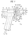
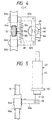
- FIGs. 1 to 5 A C ring clamping device which is a preferred embodiment of the present invention is shown in FIGs. 1 to 5.
- a C ring clamping device body 10 is equipped with a magazine 12, jaws 14, a main pneumatic cylinder 20 for moving the jaws 14 pivotally, and a direction control valve 22 of push button type.
- a push button 24 of the direction control valve 22 protrudes out of the C ring clamping device body 10, and a trigger 26 for pushing the push button 24 is provided.
- the C ring clamping device body 10 is further equipped with an air passage 30 communicating with an pneumatic pressure inlet port of the direction control valve 22.
- One end of an air hose 32 is connected to the air passage 30, while the other end of the air hose 32 can be connected to a pneumatic pressure supply equipment (not shown).
- Air passages 34, 36 communicating with respective outlet ports of the direction control valve 22 are provided in the C ring clamping device body 10.
- the air passage 30 is connected to a port 20a of the main pneumatic cylinder 20.
- a port 20b of the main pneumatic cylinder 20 is connected to the air passage 36.
- the air passage 30 is connected to the port 20b of the main pneumatic cylinder 20.
- the port 20a of the main pneumatic cylinder 20 is connected to the air passage 34.
- a feed pneumatic cylinder 42 is attached to the C ring clamping device body 10 with a bracket 40 between. As shown in FIG. 6, the port 20a of the main pneumatic cylinder 20 is connected to the feed pneumatic cylinder 42.
- a spring 52 is provided between a piston 50 of the feed pneumatic cylinder 42 and an pneumatic cylinder body 44 of the feed pneumatic cylinder 42.
- a movable member 60 is attached to a piston rod 46 of the feed pneumatic cylinder 42.
- a pair of support members 62a and 62b is attached to the movable member 60 pivotally around a line perpendicular to the plane of FIG. 4.
- One end of a spring 68 is fixed to the support member 62a, while the other end of the spring 68 is fixed to the support member 62b.
- An one-way bearing 64a which rotates only counterclockwise in FIG. 1 is attached to the support member 62a.
- Another one-way bearing 64b which rotates only clockwise in FIG. 1 is attached to the support member 62b.
- a feed member 66a is mounted on the one- way bearing 64a, while another feed member 66b is mounted on the one-way bearing 64b. The feed members 66a, 66b are placed in the position to be in contact with C rings being engaged with the magazine 12.
- a bracket 70 is mounted on the C ring clamping device body 10.
- An arm 72 is attached pivotally to the bracket 70.
- An one-way bearing 74 which rotates only clockwise in FIG. 2 is attached to the arm 72.
- a pressure wheel 76 is mounted on the one-way bearing 74.
- a rod 80 is further attached to the arm 72.
- a coil spring 78 is used to connect the arm 72 with the bracket 70 resiliently.
- a flat spring 90 made of spring steel is held between the pneumatic cylinder body 44 of the feed pneumatic cylinder 42 and the bracket 40, while the other end of the flat spring 90 is fixed to the arm 72.
- the flat spring 90 is bent at end portion of a slit 92 of a semicircular arc shape opened in the flat spring 90. Then, an extrusion portion 94 extruding toward the neighborhood of the feed members 66a, 66b for the magazine 12 is formed.
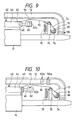
- FIGs. 7 and 8 a C ring assembly to be loaded into the magazine 12 of the C ring clamping device illustrated in FIGs. 1 to 5 is shown. As shown, a large number of C rings 102 are arranged in a row, and an adhesive tape 104 is bonded to the backs of the C rings 102 to form a C ring assembly 100 comprising the unified C rings 102.
- the direction control valve 22 changes its position into position c via position b. Then, compressed air is supplied from the pneumatic pressure supply equipment to the port 20b of the main pneumatic cylinder 20, the main pneumatic cylinder 20 is retracted and the jaws 14 are closed. As the result, the shape of the C ring 102 is changed by the jaws 14 to clamp a material to be clamped (not shown).
- the direction control valve 22 After that, if the trigger 26 is released, the direction control valve 22 returns into position a via position b. Then, compressed air is supplied from the pneumatic pressure supply equipment to the port 20a of the main pneumatic cylinder 20, the main pneumatic cylinder 20 is extended and the jaws 14 are opened. Thus, clamping is made.
- the feed members 66a, 66b are moved to the right in FIG. 1. Further, the feed members 66a, 66b are being pressed by the spring 68 to the C ring assembly 100 mounted to the magazine 12. Furthermore, the feed member 66a does not rotate clockwise in FIG. 1 due to the one-way bearing 64a, and the feed member 66b does not rotate counterclockwise in FIG. 1 due to the one-way bearing 64b. Therefore, the C ring assembly 100 is fed forward being pushed the forward portion by the feed members 66a, 66b. Thus, the first C ring 102 of the C ring assembly 100 is fed into the jaws 14 being opened.
- the feed members 66a, 66b are moved to the left in FIG. 1.
- the pressure wheel 76 is pressed to the C ring assembly 100 by the coil spring 78 and the extrusion portion 94 is pressed to the adhesive tape 104 of the C ring assembly 100.
- the feed member 66a rotates counterclockwise in FIG. 1 and the feed member 66b rotates clockwise in FIG. 1. Therefore, the C ring assembly 100 mounted on the magazine 12 never moves back.
- materials to be clamped are clamped with the C ring 102 by pulling the trigger 26 and the C ring 102 is fed into the jaws 14 portion by releasing the trigger 26.
Landscapes
- Engineering & Computer Science (AREA)
- Mechanical Engineering (AREA)
- Automatic Assembly (AREA)
- Hand Tools For Fitting Together And Separating, Or Other Hand Tools (AREA)
- Manufacturing Of Electrical Connectors (AREA)
- Seal Device For Vehicle (AREA)
Claims (9)
- Dispositif pour sertir des agrafes comprenant :a) un corps de dispositif (10) pour sertir des agrafes ;b) un magasin d'agrafes monté sur ledit corps de dispositif (10) pour sertir les agrafes ;c) des mâchoires (14) réalisées dans ledit corps de dispositif (10) pour sertir des agrafes ;d) un vérin pneumatique principal pour déplacer lesdites mâchoires (14) d'une manière pivotante ;
caractérisé en ce que le dispositif pour sertir des agrafes comprend en outree) un vérin pneumatique d'amenée (42) fixé audit corps de dispositif (10) pour sertir les agrafes ;f) au moins un élément d'amenée (66a) monté sur une tige de piston (46) dudit vérin pneumatique d'amenée (42) avec un moyen de rotation unidirectionnel (64a) entre et mis dans une position pour être en contact avec un ensemble d'agrafes (100a, 100b) chargé dans ledit magasin d'agrafes (12) ;g) un ressort plat (90) dont les deux extrémités sont fixées à des parties dudit corps de dispositif (10) pour sertir les agrafes ; eth) une portion d'extrusion réalisée dans ledit ressort plat (90) et extrudée vers le voisinage dudit élément d'amenée (66a) dans une position pour être en contact avec ledit ensemble d'agrafes (100a, 100b). - Dispositif pour sertir des agrafes selon la revendication 1, où ledit ressort plat (90) est réalisé en acier à ressort.
- Dispositif pour sertir des agrafes selon la revendication 1, où ladite portion d'extrusion (94) est formée dans ledit ressort plat (90) en ouvrant une fente (92) d'une forme d'arc semi-circulaire dans ledit ressort plat (90) et en pliant ledit ressort plat (90) à une portion d'extrémité de ladite fente (92).
- Dispositif pour sertir des agrafes selon la revendication 1, où un support (70) est monté sur ledit corps de dispositif (10) pour sertir les agrafes, un bras (72) est fixé d'une manière pivotante audit support (70), un palier à un chemin (74) est fixé audit bras (72), une roue de pression (76) est montée sur ledit palier à un chemin (74), et un ressort hélicoïdal (78) est utilisé pour relier ledit bras audit support (70) d'une manière élastique.
- Dispositif pour sertir des agrafes selon la revendication 4, où une tige (80) est fixée audit bras (72).
- Dispositif pour sertir des agrafes selon la revendication 4 ou 5, où une extrémité dudit ressort plat (90) est retenue entre ledit vérin pneumatique d'amenée (42) et un support (40) pour monter ledit cylindre pneumatique d'amenée (42) sur ledit corps de dispositif (10) pour sertir les agrafes.
- Dispositif pour sertir des agrafes selon la revendication 6, où une autre extrémité dudit ressort plat (90) est fixée audit bras (72).
- Dispositif pour sertir des agrafes selon la revendication 1, où ladite agrafe est une bague en C (102).
- Dispositif pour sertir des agrafes selon la revendication 1, où deux éléments d'amenée (66a, 66b) sont prévus des deux côtés dudit magasin (12).
Applications Claiming Priority (3)
| Application Number | Priority Date | Filing Date | Title |
|---|---|---|---|
| JP8017632A JP2771963B2 (ja) | 1996-02-02 | 1996-02-02 | ホッグリング締結装置 |
| JP17632/96 | 1996-02-02 | ||
| JP1763296 | 1996-02-02 |
Publications (2)
| Publication Number | Publication Date |
|---|---|
| EP0787564A1 EP0787564A1 (fr) | 1997-08-06 |
| EP0787564B1 true EP0787564B1 (fr) | 2001-12-05 |
Family
ID=11949249
Family Applications (1)
| Application Number | Title | Priority Date | Filing Date |
|---|---|---|---|
| EP96306375A Expired - Lifetime EP0787564B1 (fr) | 1996-02-02 | 1996-09-03 | Dispositif pour sertir des agrafes |
Country Status (5)
| Country | Link |
|---|---|
| US (1) | US5709124A (fr) |
| EP (1) | EP0787564B1 (fr) |
| JP (1) | JP2771963B2 (fr) |
| AT (1) | ATE210005T1 (fr) |
| DE (1) | DE69617625T2 (fr) |
Families Citing this family (14)
| Publication number | Priority date | Publication date | Assignee | Title |
|---|---|---|---|---|
| JP2886520B2 (ja) * | 1997-04-03 | 1999-04-26 | 明邦株式会社 | 空圧作動装置 |
| US5938099A (en) * | 1997-05-01 | 1999-08-17 | Ciccarelli; Mark A. | Rebar clip gun |
| AU9806198A (en) * | 1997-10-16 | 1999-05-03 | Stanley-Bostitch, Inc. | Ring clinching and applying device |
| JP2931299B1 (ja) * | 1998-07-21 | 1999-08-09 | 明邦株式会社 | ホッグリング締結装置 |
| US6408489B1 (en) | 2000-04-20 | 2002-06-25 | Asml Netherlands B.V. | Collated and lubricated fasteners and lubrication station |
| JP4210256B2 (ja) * | 2004-11-30 | 2009-01-14 | 株式会社メイホウテック | ホッグリング締結装置 |
| JP4510873B2 (ja) * | 2007-12-25 | 2010-07-28 | 株式会社メイホウテック | ホッグリング締結装置 |
| US9592595B2 (en) * | 2013-05-10 | 2017-03-14 | L&P Property Management Company | Tool having automated continuous feeding method for applying hog rings |
| CN103272941A (zh) * | 2013-06-07 | 2013-09-04 | 山东沂蒙电力设备有限公司 | 一种基于变压器用的u型管弯模 |
| CN105196163B (zh) * | 2015-10-20 | 2018-04-10 | 上海方格自动化系统有限公司 | 汽车雨刮接头一体式夹具 |
| DE102018103280B4 (de) | 2017-03-01 | 2022-03-31 | Adient Engineering and IP GmbH | Befestigungswerkzeug |
| CN110976578A (zh) * | 2019-12-19 | 2020-04-10 | 谢建金 | 一种五金加工的折弯装置 |
| IT202000015061A1 (it) * | 2020-06-23 | 2021-12-23 | Itg Innovation Tech Group S R L | Dispositivo di chiusura per un gruppo stampo comprendente un gruppo di sicurezza |
| IT202000015055A1 (it) * | 2020-06-23 | 2021-12-23 | Itg Innovation Tech Group S R L | Dispositivo di chiusura per un gruppo stampo |
Family Cites Families (8)
| Publication number | Priority date | Publication date | Assignee | Title |
|---|---|---|---|---|
| US3189220A (en) * | 1962-05-09 | 1965-06-15 | Fastener Corp | Fastener feed construction |
| US3628230A (en) * | 1970-01-15 | 1971-12-21 | Novelty Tool Co Inc | Hog ring gun |
| DE2410332A1 (de) * | 1974-03-05 | 1975-09-11 | Niedecker Herbert | Vorrichtung zum verschliessen von beuteln, schlaeuchen und aehnlichem folienartigen material |
| JPS6016375A (ja) * | 1983-07-08 | 1985-01-28 | 明邦株式会社 | U字形クリツプ締結装置のクリツプ送り装置 |
| JPS6077821A (ja) * | 1983-10-05 | 1985-05-02 | 明邦株式会社 | クリツプ締結装置のクリツプ送り装置 |
| US4546528A (en) * | 1984-03-06 | 1985-10-15 | Hartco Company | Clip wrapping tool apparatus |
| US4746046A (en) * | 1986-06-30 | 1988-05-24 | Senco Products, Inc. | Fastener advancing device |
| JP2507832B2 (ja) * | 1990-11-26 | 1996-06-19 | 明邦 株式会社 | ホッグリング締結装置 |
-
1996
- 1996-02-02 JP JP8017632A patent/JP2771963B2/ja not_active Expired - Fee Related
- 1996-09-03 AT AT96306375T patent/ATE210005T1/de not_active IP Right Cessation
- 1996-09-03 EP EP96306375A patent/EP0787564B1/fr not_active Expired - Lifetime
- 1996-09-03 DE DE69617625T patent/DE69617625T2/de not_active Expired - Fee Related
-
1997
- 1997-01-21 US US08/786,765 patent/US5709124A/en not_active Expired - Fee Related
Also Published As
| Publication number | Publication date |
|---|---|
| ATE210005T1 (de) | 2001-12-15 |
| US5709124A (en) | 1998-01-20 |
| EP0787564A1 (fr) | 1997-08-06 |
| JP2771963B2 (ja) | 1998-07-02 |
| JPH09207081A (ja) | 1997-08-12 |
| DE69617625D1 (de) | 2002-01-17 |
| DE69617625T2 (de) | 2002-08-08 |
Similar Documents
| Publication | Publication Date | Title |
|---|---|---|
| EP0787564B1 (fr) | Dispositif pour sertir des agrafes | |
| US7641183B2 (en) | Bar clamp with side-activated braking lever | |
| US8296935B2 (en) | Compression tool with retaining means for coaxial cable connection | |
| US8653402B2 (en) | Joining system head, joining system, and method of feeding and joining elements | |
| US5123273A (en) | Hog ring clamping device | |
| US20030075941A1 (en) | Linear slide gripper | |
| CA2593226A1 (fr) | Arretoir de cable pour tete de placement de fibres | |
| JP3707050B2 (ja) | クランプ装置 | |
| MXPA96005992A (en) | Brazier that includes internal connection elast | |
| US7518084B2 (en) | Joining system head, joining system, and method of feeding and joining elements | |
| US5595375A (en) | Self-tightening, easily releasable clamping device capable of being retained in an open position | |
| JPH02180576A (ja) | ロボット端部作動体交換システム | |
| US4679782A (en) | Mechanical toggle clamp with means for applying uniform clamping force | |
| DE112021003956T5 (de) | Teilehaltevorrichtung, Robotersystem und Teilemontageverfahren | |
| DE102008062788B4 (de) | Vorrichtung zum Befestigen von Schweineringen | |
| US7188879B2 (en) | Slide gripper assembly | |
| CN115367456B (zh) | 一种车载显示屏组装装置 | |
| JP3783944B2 (ja) | 板材曲げ加工機の押え型取り付け構造 | |
| JP2787005B2 (ja) | ホッグリング締結装置 | |
| US20030192444A1 (en) | Plate inserting apparatus | |
| JPH0230796B2 (fr) | ||
| SU1007971A2 (ru) | Схват манипул тора | |
| GB2302835A (en) | C clamp | |
| JPH0422555A (ja) | 金型クランプ装置 | |
| JP2000094146A (ja) | 交換用ガンアームの保持方法と装置 |
Legal Events
| Date | Code | Title | Description |
|---|---|---|---|
| PUAI | Public reference made under article 153(3) epc to a published international application that has entered the european phase |
Free format text: ORIGINAL CODE: 0009012 |
|
| AK | Designated contracting states |
Kind code of ref document: A1 Designated state(s): AT DE FR GB NL SE |
|
| 17P | Request for examination filed |
Effective date: 19970904 |
|
| GRAG | Despatch of communication of intention to grant |
Free format text: ORIGINAL CODE: EPIDOS AGRA |
|
| 17Q | First examination report despatched |
Effective date: 20010212 |
|
| GRAG | Despatch of communication of intention to grant |
Free format text: ORIGINAL CODE: EPIDOS AGRA |
|
| GRAG | Despatch of communication of intention to grant |
Free format text: ORIGINAL CODE: EPIDOS AGRA |
|
| GRAH | Despatch of communication of intention to grant a patent |
Free format text: ORIGINAL CODE: EPIDOS IGRA |
|
| GRAH | Despatch of communication of intention to grant a patent |
Free format text: ORIGINAL CODE: EPIDOS IGRA |
|
| GRAA | (expected) grant |
Free format text: ORIGINAL CODE: 0009210 |
|
| AK | Designated contracting states |
Kind code of ref document: B1 Designated state(s): AT DE FR GB NL SE |
|
| REF | Corresponds to: |
Ref document number: 210005 Country of ref document: AT Date of ref document: 20011215 Kind code of ref document: T |
|
| REG | Reference to a national code |
Ref country code: GB Ref legal event code: IF02 |
|
| REF | Corresponds to: |
Ref document number: 69617625 Country of ref document: DE Date of ref document: 20020117 |
|
| ET | Fr: translation filed | ||
| PLBE | No opposition filed within time limit |
Free format text: ORIGINAL CODE: 0009261 |
|
| STAA | Information on the status of an ep patent application or granted ep patent |
Free format text: STATUS: NO OPPOSITION FILED WITHIN TIME LIMIT |
|
| 26N | No opposition filed | ||
| PGFP | Annual fee paid to national office [announced via postgrant information from national office to epo] |
Ref country code: GB Payment date: 20050824 Year of fee payment: 10 |
|
| PGFP | Annual fee paid to national office [announced via postgrant information from national office to epo] |
Ref country code: SE Payment date: 20050921 Year of fee payment: 10 Ref country code: FR Payment date: 20050921 Year of fee payment: 10 |
|
| PGFP | Annual fee paid to national office [announced via postgrant information from national office to epo] |
Ref country code: NL Payment date: 20050922 Year of fee payment: 10 Ref country code: AT Payment date: 20050922 Year of fee payment: 10 |
|
| PGFP | Annual fee paid to national office [announced via postgrant information from national office to epo] |
Ref country code: DE Payment date: 20050924 Year of fee payment: 10 |
|
| PG25 | Lapsed in a contracting state [announced via postgrant information from national office to epo] |
Ref country code: AT Free format text: LAPSE BECAUSE OF NON-PAYMENT OF DUE FEES Effective date: 20060903 |
|
| PG25 | Lapsed in a contracting state [announced via postgrant information from national office to epo] |
Ref country code: SE Free format text: LAPSE BECAUSE OF NON-PAYMENT OF DUE FEES Effective date: 20060904 |
|
| PG25 | Lapsed in a contracting state [announced via postgrant information from national office to epo] |
Ref country code: NL Free format text: LAPSE BECAUSE OF NON-PAYMENT OF DUE FEES Effective date: 20070401 |
|
| PG25 | Lapsed in a contracting state [announced via postgrant information from national office to epo] |
Ref country code: DE Free format text: LAPSE BECAUSE OF NON-PAYMENT OF DUE FEES Effective date: 20070403 |
|
| EUG | Se: european patent has lapsed | ||
| GBPC | Gb: european patent ceased through non-payment of renewal fee |
Effective date: 20060903 |
|
| NLV4 | Nl: lapsed or anulled due to non-payment of the annual fee |
Effective date: 20070401 |
|
| REG | Reference to a national code |
Ref country code: FR Ref legal event code: ST Effective date: 20070531 |
|
| PG25 | Lapsed in a contracting state [announced via postgrant information from national office to epo] |
Ref country code: GB Free format text: LAPSE BECAUSE OF NON-PAYMENT OF DUE FEES Effective date: 20060903 |
|
| PG25 | Lapsed in a contracting state [announced via postgrant information from national office to epo] |
Ref country code: FR Free format text: LAPSE BECAUSE OF NON-PAYMENT OF DUE FEES Effective date: 20061002 |