EP0787926A2 - Système de transmission de puissance avec train épicycloidal à denture hélicoidale - Google Patents
Système de transmission de puissance avec train épicycloidal à denture hélicoidale Download PDFInfo
- Publication number
- EP0787926A2 EP0787926A2 EP97101813A EP97101813A EP0787926A2 EP 0787926 A2 EP0787926 A2 EP 0787926A2 EP 97101813 A EP97101813 A EP 97101813A EP 97101813 A EP97101813 A EP 97101813A EP 0787926 A2 EP0787926 A2 EP 0787926A2
- Authority
- EP
- European Patent Office
- Prior art keywords
- gear
- pinion
- carrier
- gears
- meshing
- Prior art date
- Legal status (The legal status is an assumption and is not a legal conclusion. Google has not performed a legal analysis and makes no representation as to the accuracy of the status listed.)
- Withdrawn
Links
- 230000005540 biological transmission Effects 0.000 title claims abstract description 44
- 230000000717 retained effect Effects 0.000 claims description 8
- 238000010276 construction Methods 0.000 description 12
- 238000010586 diagram Methods 0.000 description 3
- NCGICGYLBXGBGN-UHFFFAOYSA-N 3-morpholin-4-yl-1-oxa-3-azonia-2-azanidacyclopent-3-en-5-imine;hydrochloride Chemical compound Cl.[N-]1OC(=N)C=[N+]1N1CCOCC1 NCGICGYLBXGBGN-UHFFFAOYSA-N 0.000 description 1
- 241000252141 Semionotiformes Species 0.000 description 1
- 239000000969 carrier Substances 0.000 description 1
- 238000000034 method Methods 0.000 description 1
Images


Classifications
-
- F—MECHANICAL ENGINEERING; LIGHTING; HEATING; WEAPONS; BLASTING
- F16—ENGINEERING ELEMENTS AND UNITS; GENERAL MEASURES FOR PRODUCING AND MAINTAINING EFFECTIVE FUNCTIONING OF MACHINES OR INSTALLATIONS; THERMAL INSULATION IN GENERAL
- F16H—GEARING
- F16H3/00—Toothed gearings for conveying rotary motion with variable gear ratio or for reversing rotary motion
- F16H3/44—Toothed gearings for conveying rotary motion with variable gear ratio or for reversing rotary motion using gears having orbital motion
- F16H3/62—Gearings having three or more central gears
- F16H3/66—Gearings having three or more central gears composed of a number of gear trains without drive passing from one train to another
- F16H3/663—Gearings having three or more central gears composed of a number of gear trains without drive passing from one train to another with conveying rotary motion between axially spaced orbital gears, e.g. a stepped orbital gear or Ravigneaux
-
- F—MECHANICAL ENGINEERING; LIGHTING; HEATING; WEAPONS; BLASTING
- F16—ENGINEERING ELEMENTS AND UNITS; GENERAL MEASURES FOR PRODUCING AND MAINTAINING EFFECTIVE FUNCTIONING OF MACHINES OR INSTALLATIONS; THERMAL INSULATION IN GENERAL
- F16H—GEARING
- F16H2200/00—Transmissions for multiple ratios
- F16H2200/003—Transmissions for multiple ratios characterised by the number of forward speeds
- F16H2200/0047—Transmissions for multiple ratios characterised by the number of forward speeds the gear ratios comprising five forward speeds
Definitions
- the present invention relates to a power transmission system and, more particularly, to a power transmission system which is composed of a plurality of planetary gear sets for transmitting a power through the pinion gears belonging to the planetary gear set and having different diameters.
- Some power transmission system as composed in combination of a plurality of planetary gear sets, is equipped with a gear train which is constructed to include integrated larger-diameter and smaller-diameter pinion gears (as will be called the "stepped pinion" having the integrated larger- and smaller-diameter pinion gears) so that the power is transmitted, by using one of a carrier bearing the stepped pinion, a ring gear meshing with one pinion gear of the stepped pinion and a sun gear meshing with the other pinion gear as a reaction element, between the remaining two elements through the stepped pinion.
- the power transmission system thus constructed is exemplified by the technique which is disclosed in Japanese Patent Laid-Open No. 119802/1995.
- this power transmission system is usually devised to cancel the moment, which might otherwise be established in the stepped pinion to incline the pinion shaft, with a thrust force by designing the direction of the angle of torsion which is set in the tooth trace of each gear.
- the thrust force acting upon the stepped pinion become unbalance to act on another member due to the difference between the diameters of the pinion gars meshing with the sun gear and the ring gear even if the torsion angles of the two are equal.
- a thrust roller bearing having a sufficient axial supporting force so that the thrust force is supported by the carrier.
- the construction having the thrust roller bearing increases the axial size of the system to enlarge the size.
- a first object of the present invention to provide such a compact construction of a power transmission system for transmitting a power through a stepped pinion as requires no support of the thrust force of the stepped pinion.
- a second object of the present invention is to make compact a power transmission system, which is composed of a transmission mechanism for achieving five forward speeds by setting the torsion angles, as described above.
- a power transmission system comprising planetary gears including: first and second integrated pinion gears made of helical gears of different diameters; a carrier bearing the first and second pinion gears rotatably; a ring gear made of a helical gear meshing with the first pinion gear; and a sun gear made of a helical gear meshing with the second pinion gear, the power is transmitted, by using one of the carrier, the ring gear and the sun gear as a reaction element, between the remaining two elements through the first and second pinion gears, wherein the relation between the angles of torsion of the tooth traces of the first and second pinion gears is so set on the basis of the ratio between the diameters of the two helical gears that the first and second pinion gears may not exert a thrust force upon another member.
- the planetary gear sets include: a first ring gear; a first carrier for rotatably bearing the first pinion gear meshing with the ring gear; a first sun gear meshing with the first pinion gear; a second ring gear connected to the first carrier; a second carrier connected to the first ring gear for rotatably bearing a third pinion gear meshing with the second ring gear; a third sun gear meshing with the third pinion gear; and a second sun gear meshing with the second pinion gear having a smaller diameter than that of the first pinion gear; the first ring gear and the second carrier are connected to an output shaft; the first sun gear is connected to an input shaft by a first clutch and retained on a case by a first brake; the third sun gear is retained on the case by a second brake; the first carrier and the ring gear are retained on the case by a third brake and connected to the input shaft by the second clutch; and the second sun gear is retained on the case by a fourth brake.
- the relation between the torsion angles of the two pinion gears is so set the integrated first and second pinion gears, i.e., the stepped pinion may not exert the thrust force upon another member.
- the system can be made compact without requiring any thrust bearing.
- the construction as defined in claim 2 moreover, at the highest gear stage, there arises a state in which the power is transmitted from the first carrier to the first ring gear through the stepped pinion. In this state, the relative rotation between the stepped pinion and the carrier increases. If the relation between the torsion angles of the larger-diameter pinion gear and the smaller-diameter pinion gear is not proper, the stepped pinion exerts the thrust force upon another member so that a thrust bearing of a relatively high capacity is necessary. According to the construction as defined in claim 2, the relation between the torsion angles of the larger-diameter pinion gear and the smaller-diameter pinion gear is so set that the stepped pinion may not exert the thrust force upon another member. As a result, the power transmission system for achieving the five forward speeds can be made compact without requiring any thrust bearing.
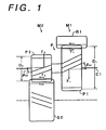
- FIG. 1 schematically shows that portion of a power transmission system constructed of a plurality of planetary gear sets M, to which is applied the present invention.
- This power transmission system is constructed of planetary gear sets M1 and M2, which are composed of: first and second pinion gears P1 and P2 made of helical gears of different diameters and integrated with each other; a carrier C1 bearing the first and second pinion gears P1 and P2 rotatably; a ring gear R1 made of a helical gear meshing with the pinion gear P1; and a sun gear S2 made of a helical gear meshing with the second pinion gear P2.
- the power is transmitted, by using one (i.e., the sun gear S2 in the present embodiment) of the carrier C1, the ring gear R1 and the sun gear S2a sun gear made of a helical gear meshing with said second pinion gear as a reaction element, between the remaining two elements (i.e., the carrier C1 and the ring gear R1 in the present embodiment) through the first and second pinion gears P1 and P2.
- the setting of the aforementioned angles of torsion is executed in the following manner. It is assumed in the following calculation that both the thrust force and the tangential force of the torque be exerted upon the meshing pitch circles. With reference to the torsion angle ⁇ D1 on the reference pitch circle of the first pinion gear P1, there is determined such a torsion angle ⁇ D2 on the reference pitch angle of the second pinion gear P2 as will cancel the thrust force to be produced in the stepped pinion P.
- the relation between the torsion angle ⁇ D1 of the tooth trace of the lager-diameter pinion P1 and the torsion angle ⁇ D2 of the tooth trace of the smaller-diameter pinion P2 is so set that the stepped pinion P itself may not exert the thrust force upon another member.
- the gear meshing engagements simultaneously occur for the plurality of gears.
- the meshing positions of the individual teeth move from the top to the root, as viewed in the axial direction, and vice versa as the meshing engagements proceed.
- the strict calculations would be very complicated. However, simple calculations can give sufficiently practical values even if it is assumed, as in the aforementioned example of calculations, that the thrust force acts upon the meshing pitch circle.
- a transmission T is constructed of: a torque converter 12 having a lockup clutch 11; three stages of planetary gear sets M1, M2 and M3; and four brakes (B-0 L , B-0 H , B-1 and B-2) and two clutches (C-1 and C-2) arranged in association with them.
- the planetary gear set M1 is equipped with a first sun gear S1, a second ring gear R1, a first pinion gear P1 meshing with them, and a first carrier C1 bearing them rotatably.
- the planetary gear set M2 is equipped with a second sun gear S2, and a second pinion gear P2 meshing with the second sun gear S2 and having a smaller diameter than that of the pinion gear P1 which meshes with the second sun gear S2, and the pinion gear P2 is rotatably borne by the carrier C1 and is integrated with the pinion gear P1.
- the third planetary gear set M3 is equipped with a third sun gear S3, a second ring gear R3, and a second carrier rotatably bearing a third pinion gear P3 meshing with them.
- the individual ring gears R1 and R3 and carriers C3 and C1 of the two gear sets M1 and M3 are connected to each other.
- the sun gear S1 and the carrier C1 of the gear set M1 are so respectively connected through the first and second clutches (C-1 and C-2) to an input shaft 14 leading to a turbine shaft 13 of the torque converter 12 that they may act as the input elements.
- the ring gear R1 and the carrier C3, as connected to each other, are connected through an output shaft 15 to a counter drive gear 19 acting as the output element.
- the sun gear S1 of the gear set M1 can be fixed on a transmission case 10 by the first brake (B-0 L ), and the sun gear S3 of the gear set M3 can also be fixed on the transmission case 10 by the second brake (B-1).
- the ring gear R3, as connected to the carrier C1 can be fixed on the transmission case 10 by the third brake (B-2).
- the sun gear S1 is connected to the clutch (C-1) through a sun gear shaft 16 fitted on the outer circumference of the input shaft 14.
- the carrier C1 is connected to the clutch (C-2) through a carrier shaft 17 fitted on the outer circumference of the input shaft 14.
- the sun gear S3 is connected to the brake (B-1) through a sun gear shaft 18 fitted on the outer circumference of the carrier shaft 17.
- the individual brakes other than the brake (B-2) are made of band brakes whereas the brake (B-2) is made of wet type multiple discs, although not limited thereto.
- the counter drive gear 19 is connected to a differential unit 21 through a counter gear 20 fixed on a counter shaft 20, to construct a transmission having a transverse construction.
- first and second clutches (C-1 and C-2) are arranged across the transmission mechanism M, and their first and second hydraulic servos 3 and 4 are confined in the side walls 10a and 10b, respectively, at the two axial end portions of the transmission case 10.
- These first and second hydraulic servos 3 and 4 are made of stationary type first and second cylinders 30 and 40, respectively, which are formed to confront each other in the respective side walls 10a and 10b of the transmission case 10.
- the first and second hydraulic servos 3 and 4 are equipped with: first and second pistons 31 and 41 which are slidably arranged in those cylinders 30 and 40 and associated with the first and second cylinders 30 and 40, respectively, to define oil chambers 3C and 4C to be fed with the oil pressure; and first and second bearings 32 and 42 arranged between the pistons 31 and 41 and the first and second clutches (C-1 and C-2), respectively, to allow the relative rotations between the first and second pistons 31 and 41 and the first and second clutches (C-1 and C-2) and to transmit the pushing forces of the first and second pistons 31 and 41 in accordance with the feeds of the oil pressure, respectively, to the first and second clutches (C-1 and C-2).
- the first and second hydraulic servos 3 and 4 are equipped with push members 33 and 43, respectively, between the first and second bearings 32 and 42 and the first and second clutches (C-1 and C- 2).
- the push members 33 and 43 confront the bearings 32 and 42 at the inner circumferential sides and the clutches (C-1 and C-2) at the outer circumferential sides.
- Fig. 4 shows a section of the portion, to which is applied the present invention, in detail.
- the stepped pinion P is rotatably borne in the radial direction on a pinion shaft 51 through a bearing bush 52 and is axially positioned between carrier flanges 53 and 54 supporting the pinion shaft 51 across washers 55 and 56.
- the sun gear S1 is splined to the stepped portion of the sun gear shaft 16 and is supported in the radial direction on the input shaft 14 through a roller bearing 57 supporting the sun gear shaft 16 and in the thrust direction on the end face of the stepped portion and a thrust bearing 58.
- the second sun gear S2 is supported in the radial direction on the sun gear shaft 16 by a roller bearing 59 and in the thrust direction on the flange portion of the sun gear shaft and the carrier flange 54 through thrust bearings 60 and 61.
- the description of the remaining portions will be omitted by designating the corresponding members by reference numerals similar to those of Fig. 2.
- the transmission thus constructed achieves the individual gear stages by feeding the oil pressure to the hydraulic servos corresponding to the individual clutches and brakes under the control of the not-shown hydraulic control unit thereby to apply (as indicated by symbols ⁇ )) and release (as indicated by no symbol) the individual clutches and brakes, as operationally tabulated in Fig. 3.
- the first speed (1ST) is achieved when the clutch (C-1) and the brake (B-1) are applied.
- the rotation of the input shaft 14 is transmitted through the clutch (C-1) to the sun gear S1 until it is outputted as the rotation of the carrier C2, which is the most decelerated with the sun gear S3 being fixed by the application of the brake (B-1), to the counter drive gear 19.
- the second speed (2ND) is achieved by applying the clutch (C-2) and the brake (B-1).
- the input, as transmitted through the clutch (C-2) to the carrier shaft 17, enters, as it is, to the ring gear R3 through the carrier C1 until it is outputted as the differential rotation of the carrier C3, by which the sun gear S3 fixed by the application of the brake (B-1) is used as the reaction element, to the counter drive gear 19.
- the third speed (3RD) is achieved by directly connecting the first planetary gear set M1 by the applications of the two clutches (C-1 and C-2). At this time, the rotation of the input shaft 14 is outputted, as it is, as the rotation of the carrier C3 to the counter drive gear 19.
- the fourth speed (4TH) by the overdrive is achieved by applying the clutch (C-2) and the brake (B-O L ) for fixing the sun gar S1.
- the rotation of the input shaft 14 is transmitted, as the rotation of the ring gear R1 the speed of which is increased by the autorotation of the pinion gear P1 from the rotation of the carrier C1, from the carrier C3 to the counter drive gear 19.
- the 5th speed is achieved by applying the clutch (C-2) and the brake (B-0 H ).
- the reverse (REV) is achieved by applying the clutch (C-1) and the brake (B-2). At this time, the rotation of the ring gear R1, as reversed and decelerated from the input of the sun gear S1 by fixing the carrier C1, is outputted through the carrier C3 to the counter drive gear 19.
- the torque of the input shaft 14 enters the smaller-diameter sun gear S1, as splined to the sun gear shaft 16, and is transmitted through the larger-diameter pinion gear P1 to the ring gear R1 and the carrier C3 so that the power transmission is executed by the first planetary gear set M1.
- the torsion angle of the tooth trace of the pinion gear P1 and the diameter of the helical gear are naturally equalized at the meshing side with the sun gear S1 and the meshing side with the ring gear R1.
- the thrust forces to be applied to the pinion gear P1 have inverse directions and equal magnitudes at the meshing side with the sun gear S1 and the meshing side with the ring gear R1 so that no axial unbalance force acts upon the pinion gear P1, i.e., the stepped pinion P.
- the power is transmitted through the carrier C1 only to the ring gear R3 of the third planetary gear set M3, as described before, so that the stepped pinion P does not participate in the power transmission.
- the first planetary gear set M1 takes the direct connection, as described before, so that the power transmission is neither performed by the autorotation of the stepped pinion P.
- the fourth speed (4TH) there is performed the power transmission of the torque output of the ring gear R1, the speed of which is increased by the autorotation of the pinion gear P1 by the reaction of the fixed sun gear S1 from the torque input coming from the carrier C1.
- the power is transmitted, as at the first speed (1ST), only by the first planetary gear set M1 so that no axial unbalance force does not act, for the same reason as the aforementioned one, upon the pinion gear P1, i.e., the stepped pinion P.
- the power transmission of the rotation of the ring gear R1 the speed of which is further increased from that of the fourth speed by the autorotation of the smaller-diameter pinion gear P2 taking the reaction on the larger-diameter sun gear S2.
- the power is transmitted across the first and second pinion gears P1 and P2, and the relative rotation between the stepped pinion P and the carrier C1 is increased.
- the thrust force to be applied to the stepped pinion P is offset to exert no action on another member.
- the stepped pinion P can be held in the predetermined axial position by the simple construction in which the flat washers 55 and 56 are sandwiched between the carrier C1 and the end face of the stepped pinion P.
- the present invention has been described in connection with its embodiment, it should not be limited to the specific construction which has been exemplified in the embodiment, but a variety of specific constructions can be applied to a wide variety of planetary gear sets.
- the torsion direction of the helical gears can be inverted from that of the embodiment to cancel the separate force, which has troubled the prior art, while balancing the thrust force acting upon the stepped pinion.
Landscapes
- Engineering & Computer Science (AREA)
- General Engineering & Computer Science (AREA)
- Mechanical Engineering (AREA)
- Structure Of Transmissions (AREA)
- Retarders (AREA)
- Gear Transmission (AREA)
Applications Claiming Priority (2)
| Application Number | Priority Date | Filing Date | Title |
|---|---|---|---|
| JP8040308A JPH09210152A (ja) | 1996-02-05 | 1996-02-05 | 動力伝達装置 |
| JP40308/96 | 1996-02-05 |
Publications (2)
| Publication Number | Publication Date |
|---|---|
| EP0787926A2 true EP0787926A2 (fr) | 1997-08-06 |
| EP0787926A3 EP0787926A3 (fr) | 1998-04-01 |
Family
ID=12576998
Family Applications (1)
| Application Number | Title | Priority Date | Filing Date |
|---|---|---|---|
| EP97101813A Withdrawn EP0787926A3 (fr) | 1996-02-05 | 1997-02-05 | Système de transmission de puissance avec train épicycloidal à denture hélicoidale |
Country Status (2)
| Country | Link |
|---|---|
| EP (1) | EP0787926A3 (fr) |
| JP (1) | JPH09210152A (fr) |
Cited By (4)
| Publication number | Priority date | Publication date | Assignee | Title |
|---|---|---|---|---|
| WO2005083300A1 (fr) * | 2004-02-18 | 2005-09-09 | Daimlerchrysler Ag | Engrenage toroidal pour un vehicule |
| DE102015205264A1 (de) * | 2015-03-24 | 2016-09-29 | Zf Friedrichshafen Ag | Antriebseinheit für ein Flurförderzeug und Flurförderzeug |
| EP3581830A1 (fr) * | 2018-06-13 | 2019-12-18 | Aktiebolaget SKF | Système d'engrenage |
| DE102021001879A1 (de) | 2021-04-12 | 2022-10-13 | Mercedes-Benz Group AG | Hybridantriebssystem für ein Kraftfahrzeug sowie Kraftfahrzeug |
Families Citing this family (2)
| Publication number | Priority date | Publication date | Assignee | Title |
|---|---|---|---|---|
| JP5961641B2 (ja) * | 2014-01-23 | 2016-08-02 | 本田技研工業株式会社 | 変速機 |
| JP6296923B2 (ja) * | 2014-06-30 | 2018-03-20 | ダイハツ工業株式会社 | 動力分割式無段変速機 |
Family Cites Families (6)
| Publication number | Priority date | Publication date | Assignee | Title |
|---|---|---|---|---|
| US3209618A (en) * | 1959-04-23 | 1965-10-05 | Zahnradfabrik Friedrichshafen | Transmission gear for motor vehicles |
| US4089238A (en) * | 1967-02-03 | 1978-05-16 | Daimler-Benz Aktiengesellschaft | Planetary gear change-speed transmission, especially for motor vehicles |
| GB1398526A (en) * | 1971-08-11 | 1975-06-25 | Rolls Royce | Epicyclic gear train |
| DE3139110C2 (de) * | 1981-09-12 | 1983-07-28 | Maag-Zahnräder & -Maschinen AG, 8023 Zürich | Mehrstufiges Zahnradgetriebe |
| DE4318338A1 (de) * | 1993-06-02 | 1994-12-08 | Dewitta Spezialmaschf | Wolfrom-Planetenzahnradgetriebe mit axial in zwei unterschiedlich verzahnte Bereiche aufgeteilten Planetenrädern |
| JPH07293644A (ja) * | 1994-04-25 | 1995-11-07 | Toyota Motor Corp | 遊星歯車装置 |
-
1996
- 1996-02-05 JP JP8040308A patent/JPH09210152A/ja active Pending
-
1997
- 1997-02-05 EP EP97101813A patent/EP0787926A3/fr not_active Withdrawn
Cited By (9)
| Publication number | Priority date | Publication date | Assignee | Title |
|---|---|---|---|---|
| WO2005083300A1 (fr) * | 2004-02-18 | 2005-09-09 | Daimlerchrysler Ag | Engrenage toroidal pour un vehicule |
| DE102015205264A1 (de) * | 2015-03-24 | 2016-09-29 | Zf Friedrichshafen Ag | Antriebseinheit für ein Flurförderzeug und Flurförderzeug |
| EP3581830A1 (fr) * | 2018-06-13 | 2019-12-18 | Aktiebolaget SKF | Système d'engrenage |
| CN110594364A (zh) * | 2018-06-13 | 2019-12-20 | 斯凯孚公司 | 传动组件 |
| US11078988B2 (en) | 2018-06-13 | 2021-08-03 | Aktiebolaget Skf | Transmission assembly |
| DE102021001879A1 (de) | 2021-04-12 | 2022-10-13 | Mercedes-Benz Group AG | Hybridantriebssystem für ein Kraftfahrzeug sowie Kraftfahrzeug |
| WO2022218724A1 (fr) | 2021-04-12 | 2022-10-20 | Mercedes-Benz Group AG | Système d'entraînement hybride pour un véhicule automobile et véhicule automobile |
| US12103398B2 (en) | 2021-04-12 | 2024-10-01 | Mercedes-Benz Group AG | Hybrid drive system for a motor vehicle, and motor vehicle |
| DE102021001879B4 (de) | 2021-04-12 | 2025-01-23 | Mercedes-Benz Group AG | Hybridantriebssystem für ein Kraftfahrzeug sowie Kraftfahrzeug |
Also Published As
| Publication number | Publication date |
|---|---|
| JPH09210152A (ja) | 1997-08-12 |
| EP0787926A3 (fr) | 1998-04-01 |
Similar Documents
| Publication | Publication Date | Title |
|---|---|---|
| US6547688B2 (en) | Automatic transmission | |
| US5533945A (en) | Five-speed automatic transmission | |
| EP0762014B1 (fr) | Boíte de vitesses automatique | |
| EP0733834A2 (fr) | Embrayage hydraulique pour transmission automatique dans des véhicules automobiles | |
| EP1030077B1 (fr) | Transmission automatique | |
| US5772552A (en) | Gear transmission unit for automatic transmission | |
| EP0766799A1 (fr) | Transmission automatique a cinq vitesses | |
| US5090952A (en) | Automatic transmission | |
| JPH02142949A (ja) | 車両用遊星歯車式変速装置 | |
| EP0388209B1 (fr) | Boîte de vitesses automatique | |
| JPH08261300A (ja) | 車両用自動変速機 | |
| EP0733827B1 (fr) | Transmission automatique pour véhicules | |
| US4653347A (en) | Planetary gear train of automatic transmission | |
| EP0787926A2 (fr) | Système de transmission de puissance avec train épicycloidal à denture hélicoidale | |
| EP0381536B1 (fr) | Boîte de vitesses automatique | |
| EP0752544B1 (fr) | Transmission automatique | |
| CN110608270B (zh) | 一种液力自动变速器 | |
| JP3329095B2 (ja) | 歯車変速装置 | |
| US5140870A (en) | Shift control system and method for selecting engagement/disengagement patterns within the same speed stage | |
| KR0183267B1 (ko) | 차량용 6속 자동 변속기의 기어 트레인 | |
| EP0809036A2 (fr) | Dispositif de support de tambour de frein à ruban pour transmission automatique | |
| JPS63243551A (ja) | 遊星歯車変速装置 | |
| KR100663664B1 (ko) | 자동변속기 | |
| CA2194356C (fr) | Transmission automatique a cinq rapports | |
| JPH09291986A (ja) | 自動変速機 |
Legal Events
| Date | Code | Title | Description |
|---|---|---|---|
| PUAI | Public reference made under article 153(3) epc to a published international application that has entered the european phase |
Free format text: ORIGINAL CODE: 0009012 |
|
| 17P | Request for examination filed |
Effective date: 19970303 |
|
| AK | Designated contracting states |
Kind code of ref document: A2 Designated state(s): DE GB |
|
| PUAL | Search report despatched |
Free format text: ORIGINAL CODE: 0009013 |
|
| AK | Designated contracting states |
Kind code of ref document: A3 Designated state(s): DE GB |
|
| STAA | Information on the status of an ep patent application or granted ep patent |
Free format text: STATUS: THE APPLICATION HAS BEEN WITHDRAWN |
|
| 18W | Application withdrawn |
Withdrawal date: 19980923 |