EP0788260A2 - Kanalschätzung - Google Patents
Kanalschätzung Download PDFInfo
- Publication number
- EP0788260A2 EP0788260A2 EP97300610A EP97300610A EP0788260A2 EP 0788260 A2 EP0788260 A2 EP 0788260A2 EP 97300610 A EP97300610 A EP 97300610A EP 97300610 A EP97300610 A EP 97300610A EP 0788260 A2 EP0788260 A2 EP 0788260A2
- Authority
- EP
- European Patent Office
- Prior art keywords
- correlation
- data
- transmission
- transmission channel
- receiving data
- Prior art date
- Legal status (The legal status is an assumption and is not a legal conclusion. Google has not performed a legal analysis and makes no representation as to the accuracy of the status listed.)
- Granted
Links
Images



Classifications
-
- H—ELECTRICITY
- H04—ELECTRIC COMMUNICATION TECHNIQUE
- H04L—TRANSMISSION OF DIGITAL INFORMATION, e.g. TELEGRAPHIC COMMUNICATION
- H04L25/00—Baseband systems
- H04L25/02—Details ; arrangements for supplying electrical power along data transmission lines
- H04L25/026—Arrangements for coupling transmitters, receivers or transceivers to transmission lines; Line drivers
-
- H—ELECTRICITY
- H04—ELECTRIC COMMUNICATION TECHNIQUE
- H04L—TRANSMISSION OF DIGITAL INFORMATION, e.g. TELEGRAPHIC COMMUNICATION
- H04L25/00—Baseband systems
- H04L25/02—Details ; arrangements for supplying electrical power along data transmission lines
- H04L25/0202—Channel estimation
- H04L25/0224—Channel estimation using sounding signals
- H04L25/0228—Channel estimation using sounding signals with direct estimation from sounding signals
- H04L25/023—Channel estimation using sounding signals with direct estimation from sounding signals with extension to other symbols
- H04L25/0236—Channel estimation using sounding signals with direct estimation from sounding signals with extension to other symbols using estimation of the other symbols
-
- H—ELECTRICITY
- H04—ELECTRIC COMMUNICATION TECHNIQUE
- H04L—TRANSMISSION OF DIGITAL INFORMATION, e.g. TELEGRAPHIC COMMUNICATION
- H04L25/00—Baseband systems
- H04L25/02—Details ; arrangements for supplying electrical power along data transmission lines
- H04L25/08—Modifications for reducing interference; Modifications for reducing effects due to line faults ; Receiver end arrangements for detecting or overcoming line faults
-
- H—ELECTRICITY
- H04—ELECTRIC COMMUNICATION TECHNIQUE
- H04L—TRANSMISSION OF DIGITAL INFORMATION, e.g. TELEGRAPHIC COMMUNICATION
- H04L25/00—Baseband systems
- H04L25/38—Synchronous or start-stop systems, e.g. for Baudot code
- H04L25/40—Transmitting circuits; Receiving circuits
Definitions
- This invention relates to a transmission apparatus and transmission method, and more particularly, is applicable to a digital cordless telephone and a receiving method to be used for this cordless telephone.
- DECT Digital European Cordless Telecommunications
- GSM Groupe Specil de Mobile
- the receiving signal is easily affected by fading due to the transmission channel condition, and receiving characteristic is apt to be degraded.
- synchronization timing is deviated and the demodulation efficiency is apt to be worsened and also the bit error rate decreases. In this event, there was a possibility that the entire system synchronizing condition might be worsened.
- an object of this invention is to provide a transmission apparatus and transmission method which are more resistant to the distortion of channel as compared with the conventional apparatus.
- a transmission apparatus comprising: pattern generation means (4A) for generating the same pattern data as those of the known pattern data (ts) contained in the transmitting data to be transmitted to the transmission channel; correlation detection means (4A) for detecting successively the correlation between the receiving data (r k ) to be received through the transmission channel and the pattern data (ts) as the correlation values (CorrRS k ); and signal processing means (4A) for demodulating the receiving data (r k ) depending upon the estimated result after successively estimating the characteristic of the transmission channel based on the correlation values.
- a transmission method comprises: a processing for obtaining the correlation between the pattern data (ts) and the receiving data (r k ) to be received through the transmission channel after generating the pattern identical with the known pattern data (ts) contained in the transmitting data to be transmitted to the transmission channel; and a processing for demodulating the receiving data (r k ) depending upon the estimated result after successively estimating the characteristic of the transmission channel depending upon the correlation values (CorrRS k ) obtained by the above mentioned processing.
- the same pattern data as the known pattern data (ts) contained in the transmission data to be transmitted to the transmission channel is generated on the receiving side, and the correlation between the pattern data (ts) and the receiving data (r k ) to be received through the transmission channel is obtained. Then, the characteristic of the transmission channel is successively estimated depending upon the correlation values (CorrRS k ), and the receiving data (r k ) is demodulated depending upon the estimated result.
- the transmission apparatus and transmission method can be easily realized, in which even if the receiving data (r k ) is distorted by the characteristic deterioration, the data can be correctly demodulated.
- a portable telephone 1 is constituted by various circuits, such as a high frequency (RF) signal processing circuit 3, a modulation-demodulation and data processing circuit 4, an audio processing circuit 5, besides a transmit-receive antenna 2. And while the audio signal transmitted is reproduced through a speaker 6, the voice of communicator is inputted through a microphone 7 and transmitted from the transmit-receive antenna 2.
- RF radio frequency
- processing circuits 3 to 5 are controlled by the central processing unit (CPU) 8 which is connected respectively to circuits 3 to 5 through bus 8.
- the CPU 9 functions based on the program stored in the read only memory (ROM) 10A and uses the random access memory (RAM) 10B as a calculation table. Also, the CPU 9 transmits and receives the data between a display operation unit 11 and has interface between communicators.
- Fig. 2 shows more in detail the portable telephone 1 centering around the receiving system.
- High frequency (RF) signal processing circuit 3 high frequency amplifies the receiving signal by a RF/IF detection circuit 3A and orthogonally detects and converts this to the digital signal by an analog-to-digital (A/D) converter 3B. Then, the receiving data is given to the modulation-demodulation and data processing circuit 4.
- RF radio frequency
- the modulation-demodulation and data processing circuit 4 demodulates the data received by the signal processing at the digital signal processor (DSP) for demodulation 4A, and conducts the synchronizing processing, the equalizing processing, the demodulation processing and the error correction processing by the frequency correction channel (FCCH) and gives the demodulated data to the DSP for audio 5A.
- This audio DSP 5A is used to demodulate the compressed audio data.
- Fading occurs due to the fact that multiple reflection waves which are reflected at various placed and having different delay times are received as composite waves. As shown in Fig. 3, this state can be modeled with transversal type filter. This figure is expressed considering the time delay for up to 5 bits and h k shows the tap coefficient to determine the signal loudness corresponding to each delay time.
- fading is shown as a sum of values multiplied data of every bit interval by the tap coefficient h k .
- fading is a result of convolution integral of each delayed bit and tap coefficient h k . Accordingly, if the entire bit delay spread (in this case, 5 bits) can be specified, the characteristic of the transmission channel can be determined by obtaining tap coefficient h k .
- the transmission channel characteristic changes as the time proceeds, and in general it is not easy to estimate it correctly.
- the unit transmission time to be allocated i.e., 1 burst
- the unit transmission time to be allocated is as short as 580 [ ⁇ sec] and the effect of fading in each burst can be considered to be almost constant.
- the tap coefficient h k is estimated in utilizing the known pattern data (training sequence) contained in the center of each burst.
- training sequence Several patterns can be considered in the training sequence. But if we pay attention only to a part of bit patterns in the known patterns having 26-bit length, the orthogonal relationship exists in the autocorrelation (AutoCorr k ) as shown in the following equation:
- ts shows training sequence.
- the receiving signal system r k can be expressed as follows using the transmitting signal system s k and the tap coefficient h k :
- the tap coefficient can be obtained by calculating the correlation value CorrRS k between the receiving signal r k and the training sequence ts, and the characteristic of the transmission channel (channel response) can be estimated. Also by detecting the timing to get correlation peak, synchronization timing can be obtained. Thus, if the estimated channel response and the synchronization timing are used, data least affected by fading can be demodulated.
- the system of this invention is to estimate the characteristic of the transmission channel based on the principle described in the foregoing paragraph.
- the most simple example is to take the peak of correlation value as the synchronizing position and makes the correlation value at that point as a parameter (tap coefficient h k ) to regulate the characteristic of the transmission channel (channel response).
- the processing method which can further increase the detection accuracy of synchronizing position is discussed in the following paragraphs.
- the energy average of correlation values CorrRS k which are obtained based on the equation (3) is obtained and the peak of this energy average is obtained to set the synchronization timing.
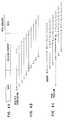
- Fig. 4B in this case ten correlation values C0, C1 ... C9 are obtained and the synchronization timing is detected based on these. This is because to obtain the most suitable value in the case where multiple peak points are produced by the effect of fading as shown in Fig. 5.
- the correlation value is weighting calculated.
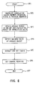
- step SP2 such as ten correlation values between the receiving signal r k and the training sequence ts is calculated for example.
- the reason why it is sufficient to obtain ten correlation values C0, C1 ... C9 is that the synchronizing position is almost known in the case of portable telephone.
- ten correlation values are values to be calculated exactly the same way as those of the tap coefficient h k to show the characteristic of the transmission channel; however, since these are used in case of confirming the synchronizing position, we will classify them different as a matter of convenience.
- step SP4 the maximum value of energy average values E0, E1 ... E5 is detected and proceeds to the processing of step SP5.
- step SP5 the synchronization timing is extracted depending upon the detected position and the synchronization timing is set.
- the characteristic of the transmission channel is set by making a group of correlation values which provides the maximum value of energy average values as tap coefficients h 0 , h 1 ... h 4 , and these processing are terminated at step SP7.
- the digital signal processor for demodulation 4A obtains the reverse characteristic filter depending upon the channel response thus obtained, and demodulates the receiving data depending upon this.
- the receiving signal r k coincides with the training sequence ts, and the correlation value C 3 is the peak point among ten correlation values. Accordingly, if the correlation value to give the peak point is detected, the position to provide the synchronization can be correctly detected.
- W i is the coefficient for weighting.
- the timing of correlation value C 2 is set as the correct synchronization timing.
- the other peak which is almost as large as C 2 is seen in the vicinity of correlation value C 6 . Therefore, if the receiving data is equalized paying no regard to this, the decline of bit error rate would be prospected.
- the result thus obtained includes correlation values C 2 and C 6 which provide two peaks as tap coefficients, and it can be considered to be very close to the actual channel response although there are some errors as compared with the method of just detecting the peak. Accordingly, if the receiving data would be demodulated based on this tap coefficient, it is considered that the receiving data can be demodulated with the lower bit error rate as compared with the previous method. Also, the latter example is more suitable for setting the synchronization timing.
- Fig. 7 shows the bit error rate and the abscissa shows the noise vs. energy ratio per bit. As shown in this figure, it is apparent that the ratio of energy per bit vs. noise becomes higher, the bit error rate decreases at the time when the synchronization timing is set in utilizing the average energy (solid line).
- the correlation value between the receiving data and the preset bit pattern (training sequence) is obtained at the portable telephone 1 side, and by estimating the channel response on the receiving channel based on the maximum correlation value, the effect of fading can be removed.
- the average energy on multiple correlation values to be obtained in time series is successively obtained in every fixed period of time, and by estimating the channel response on the receiving channel based on a set of correlation values which gives the maximum average energy among them, the effects of fading is further reduced.
- the receiving timing can be correctly extracted. And thus, a portable telephone which is capable of detecting the synchronizing condition and hard to be deviated from the synchronizing condition can be easily obtained.
- the equalizing characteristic can be improved by improving the synchronizing characteristic and as a result, the demodulation efficiency of the data can be improved. And thus, a portable telephone capable of further decreasing the bit error rate can be obtained.
Landscapes
- Engineering & Computer Science (AREA)
- Computer Networks & Wireless Communication (AREA)
- Signal Processing (AREA)
- Power Engineering (AREA)
- Mobile Radio Communication Systems (AREA)
- Monitoring And Testing Of Transmission In General (AREA)
- Synchronisation In Digital Transmission Systems (AREA)
- Digital Transmission Methods That Use Modulated Carrier Waves (AREA)
- Testing, Inspecting, Measuring Of Stereoscopic Televisions And Televisions (AREA)
Applications Claiming Priority (2)
| Application Number | Priority Date | Filing Date | Title |
|---|---|---|---|
| GB9601760A GB2309864A (en) | 1996-01-30 | 1996-01-30 | An equalizer and modulator using a training sequence and multiple correlation with a stored copy of the sequence |
| GB9601760 | 1996-01-30 |
Publications (3)
| Publication Number | Publication Date |
|---|---|
| EP0788260A2 true EP0788260A2 (de) | 1997-08-06 |
| EP0788260A3 EP0788260A3 (de) | 2000-09-06 |
| EP0788260B1 EP0788260B1 (de) | 2003-07-23 |
Family
ID=10787738
Family Applications (1)
| Application Number | Title | Priority Date | Filing Date |
|---|---|---|---|
| EP97300610A Expired - Lifetime EP0788260B1 (de) | 1996-01-30 | 1997-01-30 | Kanalschätzung |
Country Status (8)
| Country | Link |
|---|---|
| US (1) | US5978416A (de) |
| EP (1) | EP0788260B1 (de) |
| JP (1) | JP3875332B2 (de) |
| KR (1) | KR970060725A (de) |
| CN (1) | CN1121764C (de) |
| DE (1) | DE69723596T2 (de) |
| GB (1) | GB2309864A (de) |
| TW (1) | TW320804B (de) |
Cited By (2)
| Publication number | Priority date | Publication date | Assignee | Title |
|---|---|---|---|---|
| EP1061667A1 (de) * | 1999-06-11 | 2000-12-20 | Lucent Technologies Inc. | Verbesserte Kanalschätzungsmethode |
| EP1233585A1 (de) * | 2001-01-30 | 2002-08-21 | Lucent Technologies Inc. | Kanalsondierungssystem |
Families Citing this family (12)
| Publication number | Priority date | Publication date | Assignee | Title |
|---|---|---|---|---|
| JPH10145324A (ja) * | 1996-11-13 | 1998-05-29 | Sony Corp | デジタル音声放送の判別装置 |
| US6243428B1 (en) * | 1997-06-11 | 2001-06-05 | Ericsson Inc. | Method and apparatus for band-adaptive demodulation |
| GB2339120B (en) | 1998-06-30 | 2003-03-19 | Nec Technologies | Channel estimation device for digital telecommunications stations |
| GB2347831B (en) | 1999-03-06 | 2004-07-07 | Nec Technologies | Sychronisation in digital data transmission systems |
| US6791960B1 (en) | 1999-03-15 | 2004-09-14 | Lg Information And Communications, Ltd. | Pilot signals for synchronization and/or channel estimation |
| US7496132B2 (en) * | 1999-03-15 | 2009-02-24 | Kg Electronics Inc. | Pilot signals for synchronization and/or channel estimation |
| US7643540B2 (en) * | 1999-03-15 | 2010-01-05 | Lg Electronics Inc. | Pilot signals for synchronization and/or channel estimation |
| US6721299B1 (en) * | 1999-03-15 | 2004-04-13 | Lg Information & Communications, Ltd. | Pilot signals for synchronization and/or channel estimation |
| KR100294711B1 (ko) * | 1999-03-15 | 2001-07-12 | 서평원 | 최적의 파일럿 심볼을 이용한 프레임 동기 방법 |
| US7012906B1 (en) * | 1999-03-15 | 2006-03-14 | Lg Information & Communications, Ltd. | Pilot signals for synchronization and/or channel estimation |
| US8363536B2 (en) * | 2006-08-28 | 2013-01-29 | Qualcomm Incorporated | OFDM channel estimation |
| KR20130049978A (ko) * | 2011-11-07 | 2013-05-15 | 한국전자통신연구원 | 채널 추정 장치 및 방법 |
Family Cites Families (19)
| Publication number | Priority date | Publication date | Assignee | Title |
|---|---|---|---|---|
| DE3422828A1 (de) * | 1984-06-20 | 1986-01-02 | Robert Bosch Gmbh, 7000 Stuttgart | Datenempfaenger fuer aufgezeichnete daten |
| US4825448A (en) * | 1986-08-07 | 1989-04-25 | International Mobile Machines Corporation | Subscriber unit for wireless digital telephone system |
| DE4013384A1 (de) * | 1990-04-26 | 1991-10-31 | Philips Patentverwaltung | Empfaenger mit einer anordnung zur frequenzablagenschaetzung |
| DK168750B1 (da) * | 1990-05-01 | 1994-05-30 | Dancall Telecom As | Fremgangsmåde til modforvrængning i en modtager af signaler, der har passeret en transmissionskanal |
| GB2247812B (en) * | 1990-09-06 | 1994-08-31 | Motorola Inc | Equalizer for linear modulated signal |
| US5233632A (en) * | 1991-05-10 | 1993-08-03 | Motorola, Inc. | Communication system receiver apparatus and method for fast carrier acquisition |
| SE469678B (sv) * | 1992-01-13 | 1993-08-16 | Ericsson Telefon Ab L M | Saett foer synkronisering och kanalestimering i tdma- radiosystem |
| GB2271916B (en) * | 1992-10-23 | 1996-05-22 | Roke Manor Research | Improvements in or relating to digital radio communication systems |
| US5363412A (en) * | 1992-12-28 | 1994-11-08 | Motorola, Inc. | Method and apparatus of adaptive maximum likelihood sequence estimation using filtered correlation synchronization |
| US5677934A (en) * | 1992-12-30 | 1997-10-14 | Nokia Mobile Phones Limited | Multipath propagation compensation in a TDMA system |
| US5414734A (en) * | 1993-01-06 | 1995-05-09 | Glenayre Electronics, Inc. | Compensation for multi-path interference using pilot symbols |
| JPH06252699A (ja) * | 1993-03-01 | 1994-09-09 | Sony Corp | 時分割多重化処理方式における自動等化器 |
| FR2706100B1 (fr) * | 1993-03-03 | 1995-07-21 | Alcatel Mobile Comm France | Procédé pour égaliser un bloc de données en réception dans un système de communications à accès multiple à répartition dans le temps et récepteur mettant en Óoeuvre ce procédé. |
| JP3173683B2 (ja) * | 1993-03-29 | 2001-06-04 | ソニー株式会社 | 無線受信装置 |
| US5648991A (en) * | 1994-02-16 | 1997-07-15 | Kabushiki Kaisha Toshiba | Sampling phase synchronizing apparatus and bidirectional maximum likelihood sequence estimation scheme therefore |
| JPH07273713A (ja) * | 1994-04-04 | 1995-10-20 | Oki Electric Ind Co Ltd | 受信装置、基地局受信システム及び移動局受信システム |
| FI102797B (fi) * | 1994-10-07 | 1999-02-15 | Nokia Mobile Phones Ltd | Signaalin ilmaisumenetelmä TDMA-matkaviestinjärjestelmän vastaanottime ssa sekä menetelmän toteuttava vastaanotin |
| JPH08256085A (ja) * | 1995-03-17 | 1996-10-01 | Sony Corp | スペクトラム拡散通信システム及びその送信機と受信機 |
| US5748686A (en) * | 1996-04-04 | 1998-05-05 | Globespan Technologies, Inc. | System and method producing improved frame synchronization in a digital communication system |
-
1996
- 1996-01-30 GB GB9601760A patent/GB2309864A/en not_active Withdrawn
-
1997
- 1997-01-07 KR KR1019970000140A patent/KR970060725A/ko not_active Ceased
- 1997-01-16 JP JP00579197A patent/JP3875332B2/ja not_active Expired - Fee Related
- 1997-01-27 CN CN97102515A patent/CN1121764C/zh not_active Expired - Fee Related
- 1997-01-30 DE DE69723596T patent/DE69723596T2/de not_active Expired - Lifetime
- 1997-01-30 EP EP97300610A patent/EP0788260B1/de not_active Expired - Lifetime
- 1997-02-04 US US08/796,069 patent/US5978416A/en not_active Expired - Lifetime
- 1997-02-12 TW TW086101668A patent/TW320804B/zh not_active IP Right Cessation
Cited By (3)
| Publication number | Priority date | Publication date | Assignee | Title |
|---|---|---|---|---|
| EP1061667A1 (de) * | 1999-06-11 | 2000-12-20 | Lucent Technologies Inc. | Verbesserte Kanalschätzungsmethode |
| EP1233585A1 (de) * | 2001-01-30 | 2002-08-21 | Lucent Technologies Inc. | Kanalsondierungssystem |
| US7230910B2 (en) | 2001-01-30 | 2007-06-12 | Lucent Technologies Inc. | Optimal channel sounding system |
Also Published As
| Publication number | Publication date |
|---|---|
| GB2309864A (en) | 1997-08-06 |
| EP0788260B1 (de) | 2003-07-23 |
| DE69723596D1 (de) | 2003-08-28 |
| GB9601760D0 (en) | 1996-04-03 |
| KR970060725A (ko) | 1997-08-12 |
| US5978416A (en) | 1999-11-02 |
| CN1121764C (zh) | 2003-09-17 |
| CN1167378A (zh) | 1997-12-10 |
| TW320804B (de) | 1997-11-21 |
| DE69723596T2 (de) | 2004-05-27 |
| JPH09214417A (ja) | 1997-08-15 |
| JP3875332B2 (ja) | 2007-01-31 |
| EP0788260A3 (de) | 2000-09-06 |
Similar Documents
| Publication | Publication Date | Title |
|---|---|---|
| JP3147124B2 (ja) | ディジタル送信システム用受信機 | |
| US8442146B2 (en) | Apparatus and methods for reducing channel estimation noise in a wireless transceiver | |
| US6954495B2 (en) | Optimization of channel equalizer | |
| EP0788260B1 (de) | Kanalschätzung | |
| JP2556179B2 (ja) | ダイバーシティ受信方式 | |
| US20100316175A1 (en) | Packet detection, synchronization, and frequency offset estimation | |
| JPH04323926A (ja) | 直接スペクトラム拡散信号用受信機 | |
| US6327315B1 (en) | Method for estimating impulse response, and receiver | |
| EP1117187A2 (de) | Verfahren und Vorrichtung zum Erkennen einer Empfangsweg in einem CDMA System | |
| WO2002051059A2 (en) | Method of signal quality estimation | |
| Yue et al. | Performance comparisons of channel estimation techniques in multipath fading CDMA | |
| Dhar et al. | Equalized Megahertz-Bandwidth HF Channels for Spread Spectrum Communications | |
| US7212591B2 (en) | Methods and receivers that estimate multi-path delays by removing signal rays from a power-delay profile | |
| US6895044B2 (en) | Method for noise energy estimation in TDMA systems | |
| US6421380B1 (en) | Demodulator for digital communication systems | |
| US8619884B2 (en) | Communication channel estimation | |
| JP2007523553A (ja) | 周波数補償通信受信 | |
| US7428276B2 (en) | Method and apparatus for channel impulse response estimation in GSM systems | |
| JP3795885B2 (ja) | 受信装置および受信制御方法 | |
| JPH11127208A (ja) | パイロットシンボル及び仮判定データシンボルを用いた同期検波方法及び移動体通信用受信装置及び干渉除去装置 | |
| JP3762162B2 (ja) | データバーストのタイミングロケーション推定方法 | |
| JPH0856186A (ja) | 伝送装置及び伝送方法 | |
| US20070281640A1 (en) | Method For Designing A Digital Reception Filter And Corresponding Receiving Device | |
| US7363011B2 (en) | Method and apparatus for estimating the impulse response of a radio channel based on a calculated correlation sequence | |
| JP2002198869A (ja) | 情報送信チャネルのインパルス応答を推定する方法 |
Legal Events
| Date | Code | Title | Description |
|---|---|---|---|
| PUAI | Public reference made under article 153(3) epc to a published international application that has entered the european phase |
Free format text: ORIGINAL CODE: 0009012 |
|
| AK | Designated contracting states |
Kind code of ref document: A2 Designated state(s): DE FI FR GB SE |
|
| PUAL | Search report despatched |
Free format text: ORIGINAL CODE: 0009013 |
|
| AK | Designated contracting states |
Kind code of ref document: A3 Designated state(s): DE FI FR GB SE |
|
| 17P | Request for examination filed |
Effective date: 20010222 |
|
| 17Q | First examination report despatched |
Effective date: 20010430 |
|
| GRAH | Despatch of communication of intention to grant a patent |
Free format text: ORIGINAL CODE: EPIDOS IGRA |
|
| GRAH | Despatch of communication of intention to grant a patent |
Free format text: ORIGINAL CODE: EPIDOS IGRA |
|
| GRAA | (expected) grant |
Free format text: ORIGINAL CODE: 0009210 |
|
| AK | Designated contracting states |
Designated state(s): DE FI FR GB SE |
|
| REG | Reference to a national code |
Ref country code: GB Ref legal event code: FG4D |
|
| REF | Corresponds to: |
Ref document number: 69723596 Country of ref document: DE Date of ref document: 20030828 Kind code of ref document: P |
|
| REG | Reference to a national code |
Ref country code: SE Ref legal event code: TRGR |
|
| ET | Fr: translation filed | ||
| PLBE | No opposition filed within time limit |
Free format text: ORIGINAL CODE: 0009261 |
|
| STAA | Information on the status of an ep patent application or granted ep patent |
Free format text: STATUS: NO OPPOSITION FILED WITHIN TIME LIMIT |
|
| 26N | No opposition filed |
Effective date: 20040426 |
|
| PGFP | Annual fee paid to national office [announced via postgrant information from national office to epo] |
Ref country code: DE Payment date: 20140122 Year of fee payment: 18 Ref country code: SE Payment date: 20140121 Year of fee payment: 18 Ref country code: FI Payment date: 20140113 Year of fee payment: 18 |
|
| PGFP | Annual fee paid to national office [announced via postgrant information from national office to epo] |
Ref country code: FR Payment date: 20140123 Year of fee payment: 18 |
|
| PGFP | Annual fee paid to national office [announced via postgrant information from national office to epo] |
Ref country code: GB Payment date: 20140121 Year of fee payment: 18 |
|
| REG | Reference to a national code |
Ref country code: DE Ref legal event code: R119 Ref document number: 69723596 Country of ref document: DE |
|
| REG | Reference to a national code |
Ref country code: SE Ref legal event code: EUG |
|
| GBPC | Gb: european patent ceased through non-payment of renewal fee |
Effective date: 20150130 |
|
| PG25 | Lapsed in a contracting state [announced via postgrant information from national office to epo] |
Ref country code: DE Free format text: LAPSE BECAUSE OF NON-PAYMENT OF DUE FEES Effective date: 20150801 Ref country code: FI Free format text: LAPSE BECAUSE OF NON-PAYMENT OF DUE FEES Effective date: 20150130 Ref country code: GB Free format text: LAPSE BECAUSE OF NON-PAYMENT OF DUE FEES Effective date: 20150130 |
|
| REG | Reference to a national code |
Ref country code: FR Ref legal event code: ST Effective date: 20150930 |
|
| PG25 | Lapsed in a contracting state [announced via postgrant information from national office to epo] |
Ref country code: SE Free format text: LAPSE BECAUSE OF NON-PAYMENT OF DUE FEES Effective date: 20150131 Ref country code: FR Free format text: LAPSE BECAUSE OF NON-PAYMENT OF DUE FEES Effective date: 20150202 |