EP0788850A1 - Verfahren und vorrichtung zur herstellung von stahlröhren und dadurch hergestellte stahlrohr - Google Patents
Verfahren und vorrichtung zur herstellung von stahlröhren und dadurch hergestellte stahlrohr Download PDFInfo
- Publication number
- EP0788850A1 EP0788850A1 EP96927863A EP96927863A EP0788850A1 EP 0788850 A1 EP0788850 A1 EP 0788850A1 EP 96927863 A EP96927863 A EP 96927863A EP 96927863 A EP96927863 A EP 96927863A EP 0788850 A1 EP0788850 A1 EP 0788850A1
- Authority
- EP
- European Patent Office
- Prior art keywords
- steel pipe
- pipe
- temperature
- welding
- reduction
- Prior art date
- Legal status (The legal status is an assumption and is not a legal conclusion. Google has not performed a legal analysis and makes no representation as to the accuracy of the status listed.)
- Granted
Links
Images






Classifications
-
- C—CHEMISTRY; METALLURGY
- C21—METALLURGY OF IRON
- C21D—MODIFYING THE PHYSICAL STRUCTURE OF FERROUS METALS; GENERAL DEVICES FOR HEAT TREATMENT OF FERROUS OR NON-FERROUS METALS OR ALLOYS; MAKING METAL MALLEABLE, e.g. BY DECARBURISATION OR TEMPERING
- C21D8/00—Modifying the physical properties of ferrous metals or ferrous alloys by deformation combined with, or followed by, heat treatment
- C21D8/10—Modifying the physical properties of ferrous metals or ferrous alloys by deformation combined with, or followed by, heat treatment during manufacturing of tubular bodies
-
- B—PERFORMING OPERATIONS; TRANSPORTING
- B21—MECHANICAL METAL-WORKING WITHOUT ESSENTIALLY REMOVING MATERIAL; PUNCHING METAL
- B21B—ROLLING OF METAL
- B21B37/00—Control devices or methods specially adapted for metal-rolling mills or the work produced thereby
- B21B37/74—Temperature control, e.g. by cooling or heating the rolls or the product
-
- B—PERFORMING OPERATIONS; TRANSPORTING
- B21—MECHANICAL METAL-WORKING WITHOUT ESSENTIALLY REMOVING MATERIAL; PUNCHING METAL
- B21C—MANUFACTURE OF METAL SHEETS, WIRE, RODS, TUBES, PROFILES OR LIKE SEMI-MANUFACTURED PRODUCTS OTHERWISE THAN BY ROLLING; AUXILIARY OPERATIONS USED IN CONNECTION WITH METAL-WORKING WITHOUT ESSENTIALLY REMOVING MATERIAL
- B21C37/00—Manufacture of metal sheets, rods, wire, tubes, profiles or like semi-manufactured products, not otherwise provided for; Manufacture of tubes of special shape
- B21C37/06—Manufacture of metal sheets, rods, wire, tubes, profiles or like semi-manufactured products, not otherwise provided for; Manufacture of tubes of special shape of tubes or metal hoses; Combined procedures for making tubes, e.g. for making multi-wall tubes
- B21C37/08—Making tubes with welded or soldered seams
-
- B—PERFORMING OPERATIONS; TRANSPORTING
- B21—MECHANICAL METAL-WORKING WITHOUT ESSENTIALLY REMOVING MATERIAL; PUNCHING METAL
- B21C—MANUFACTURE OF METAL SHEETS, WIRE, RODS, TUBES, PROFILES OR LIKE SEMI-MANUFACTURED PRODUCTS OTHERWISE THAN BY ROLLING; AUXILIARY OPERATIONS USED IN CONNECTION WITH METAL-WORKING WITHOUT ESSENTIALLY REMOVING MATERIAL
- B21C37/00—Manufacture of metal sheets, rods, wire, tubes, profiles or like semi-manufactured products, not otherwise provided for; Manufacture of tubes of special shape
- B21C37/06—Manufacture of metal sheets, rods, wire, tubes, profiles or like semi-manufactured products, not otherwise provided for; Manufacture of tubes of special shape of tubes or metal hoses; Combined procedures for making tubes, e.g. for making multi-wall tubes
- B21C37/08—Making tubes with welded or soldered seams
- B21C37/0807—Tube treating or manipulating combined with, or specially adapted for use in connection with tube making machines, e.g. drawing-off devices, cutting-off
-
- B—PERFORMING OPERATIONS; TRANSPORTING
- B21—MECHANICAL METAL-WORKING WITHOUT ESSENTIALLY REMOVING MATERIAL; PUNCHING METAL
- B21C—MANUFACTURE OF METAL SHEETS, WIRE, RODS, TUBES, PROFILES OR LIKE SEMI-MANUFACTURED PRODUCTS OTHERWISE THAN BY ROLLING; AUXILIARY OPERATIONS USED IN CONNECTION WITH METAL-WORKING WITHOUT ESSENTIALLY REMOVING MATERIAL
- B21C37/00—Manufacture of metal sheets, rods, wire, tubes, profiles or like semi-manufactured products, not otherwise provided for; Manufacture of tubes of special shape
- B21C37/06—Manufacture of metal sheets, rods, wire, tubes, profiles or like semi-manufactured products, not otherwise provided for; Manufacture of tubes of special shape of tubes or metal hoses; Combined procedures for making tubes, e.g. for making multi-wall tubes
- B21C37/30—Finishing tubes, e.g. sizing, burnishing
-
- B—PERFORMING OPERATIONS; TRANSPORTING
- B21—MECHANICAL METAL-WORKING WITHOUT ESSENTIALLY REMOVING MATERIAL; PUNCHING METAL
- B21B—ROLLING OF METAL
- B21B17/00—Tube-rolling by rollers of which the axes are arranged essentially perpendicular to the axis of the work, e.g. "axial" tube-rolling
- B21B17/14—Tube-rolling by rollers of which the axes are arranged essentially perpendicular to the axis of the work, e.g. "axial" tube-rolling without mandrel, e.g. stretch-reducing mills
-
- B—PERFORMING OPERATIONS; TRANSPORTING
- B21—MECHANICAL METAL-WORKING WITHOUT ESSENTIALLY REMOVING MATERIAL; PUNCHING METAL
- B21B—ROLLING OF METAL
- B21B45/00—Devices for surface or other treatment of work, specially combined with or arranged in, or specially adapted for use in connection with, metal-rolling mills
- B21B45/02—Devices for surface or other treatment of work, specially combined with or arranged in, or specially adapted for use in connection with, metal-rolling mills for lubricating, cooling, or cleaning
- B21B45/0203—Cooling
- B21B45/0209—Cooling devices, e.g. using gaseous coolants
- B21B45/0215—Cooling devices, e.g. using gaseous coolants using liquid coolants, e.g. for sections, for tubes
- B21B2045/0227—Cooling devices, e.g. using gaseous coolants using liquid coolants, e.g. for sections, for tubes for tubes
-
- B—PERFORMING OPERATIONS; TRANSPORTING
- B21—MECHANICAL METAL-WORKING WITHOUT ESSENTIALLY REMOVING MATERIAL; PUNCHING METAL
- B21B—ROLLING OF METAL
- B21B37/00—Control devices or methods specially adapted for metal-rolling mills or the work produced thereby
- B21B37/78—Control of tube rolling
-
- B—PERFORMING OPERATIONS; TRANSPORTING
- B21—MECHANICAL METAL-WORKING WITHOUT ESSENTIALLY REMOVING MATERIAL; PUNCHING METAL
- B21B—ROLLING OF METAL
- B21B45/00—Devices for surface or other treatment of work, specially combined with or arranged in, or specially adapted for use in connection with, metal-rolling mills
- B21B45/004—Heating the product
Definitions
- This invention relates to a method for reducing a steel pipe, an apparatus for carrying out the method, and steel pipes prepared by the method and more particularly, to a method for reducing a steel pipe which is made by subjecting both edges of an open pipe to butt welding, an apparatus for carrying out the method, and the steel pipe.
- a solid phase welding pipe-making process i.e. a solid phase pressure-welding pipe-making process
- a butt-welding process wherein an open pipe formed by continuously forming a steel strip in the form of a pipe is entirely heated to high temperatures and is pressure-welded at both edges thereof
- a welding pipe-making process wherein an open pipe is welded at both edges thereof such as by electric resistance welding, laser welding or the like.
- the solid phase welding process is usually adapted for mass production of small diameter pipes with an outer diameter of 115 mm or below.
- this process is disadvantageous in that since the open pipe is heated to high temperatures from the outer peripheries thereof, a scale loss becomes so great that the resultant product becomes poor in surface texture.
- the welding process only both edges of the open pipe are heated to temperatures higher than the melting point at the time of the welding. The portions other than the edges are in a cold condition of 100 °C or below. Thus, the problem of the surface roughening as experienced in the solid phase welding process does not arise.
- An object of the invention is to solve the problems of the prior art and to provide a method and apparatus for reducing a steel pipe wherein a steel mother pipe prepared according to a slid phase joint or welding process or a welding process is reducible at low load and while suppressing work hardening without worsening the surface properties and wherein the dimensional accuracy of a product steel pipe can be maintained at a high level. Disclosure of The Invention
- the invention provides a method for preparing a steel pipe by continuously forming a steel strip to form an open pipe, subjecting to butt welding at both edges thereof, and reducing the welded steel pipe by means a plural-stand reducer having caliber rolls, characterized in that the steel pipe prior to the reduction is heated to a temperature of higher than 100 °C to lower than 800 °C and then reduced.
- the making of the pipe through the butt welding is intended to mean the following weldings.
- the pipe manufacture can be beneficially performed by measuring steel pipe temperatures at an inlet side and an outlet side of a reducer and also at interstand position or positions and heating or cooling the steel pipe prior to or on the way of the reduction so that the measured values are, respectively, coincident with a preset value.
- the steel pipe prior to the reduction is heated to 725 °C or below and reduced in a temperature range of 375 °C or above. Moreover, it is preferred to soak the steel pipe prior to the reduction in such a way that a temperature difference along the circumferential direction of the pipe is within 200 °C . More preferably, the steel pipe prior to the reduction is soaked so that a temperature difference along the circumferential direction of the pipe is within 100 °C . In this case, it is more favorable to measure the pipe temperatures at the inlet and outlet sides of the reducer and at interstand positions and to heat or cool the steel pipe prior to and on the way of the reduction so that the measured values are coincident with a preset value.
- the apparatus of the invention for appropriately carrying out the method of the invention is a steel pipe-reducing apparatus of the type which comprises a solid phase butt-welding device or a welding device, an inlet side heating furnace, and a reducer composed of a plurality of stands sequentially located in this order, thermometers for measuring a steel pipe at inlet and outlet sides of the reducer, and an arithmetic control unit for controlling the inlet side heating furnace based on the measured values from the thermometers, characterized in that an inlet side soaking device capable of both heating and cooling is provided in place of the inlet side heating furnace, thermometers and an interstand soaking device capable of both heating and cooling are, respectively, provided between the stands of the reducer, and the arithmetic control device controls the inlet side soaking device and the interstand soaking device based on the measured values from the thermometers between the stands.
- heating means of the inlet side and interstand soaking devices are, respectively, constituted of a heating furnace or an induction coil
- the product steel pipe according to the invention is characterized in that the pipe consists of a seam butt-welded steel pipe and that a surface roughness, Rmax, is 10 ⁇ m or below as reduced. Thus, the pipe has good characteristics.
- Fig. 1 is a schematic view of an installation arrangement for carrying out the invention.
- Fig. 2 is a schematic view of another installation arrangement for carrying out the invention.
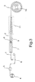
- Fig. 3 is a schematic view of a prior art method of the cold reduction of a steel pipe.
- Fig. 4 is a schematic view of a prior art method of the hot reduction of a steel pipe.
- Fig. 5 is a graph showing the relation between the heating temperature for a mother pipe and the surface roughness, Rmax. of a product steel pipe.
- Fig. 6 is a graph showing the rolling temperature dependency of a yield point and an elongation of a product steel pipe.
- Fig. 7 is a graph showing the relation between the temperature difference of a mother pipe along the circumferential direction of the pipe and the thickness deviation.
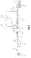
- Fig. 8 is a schematic view of a control system used in a conventional reducing temperature control.
- Fig. 9 is a schematic view showing an example of a reducer for steel pipes used in Example of the invention.
- Fig. 10 is a graph showing the total value of rolling loads at each of stands in Example.
- Fig. 11 is a graph showing the number of galling defects on the surfaces of each of product steel pipes in Example.
- Fig. 12 is a graph showing the total value of rolling loads at each of stands in another Example.
- Fig. 13 is a graph showing the number of galling defects on the surfaces of each of product steel pipes in another Example.
- Fig. 14 is a graph showing the relation between the heating temperature and the surface roughness, Rmax, in Example.
- Fig. 15 is a graph showing the relation between the rolling temperature at a final stand and the elongation in Example.
- Fig. 16 is a graph showing the relation between the heating temperature and the surface roughness, Rmax, in another Example.
- Fig. 17 is a graph showing the relation between the rolling temperature at a final stand and the elongation in another Example.
- Fig. 3 is a schematic view showing a method for the cold reduction of a steel pipe obtained by a welding process, in which designated by 1 is a steel strip, by 2 is a mother pipe prior to reduction, by 3 is a product pipe, by 4 is an uncoiler, by 5 is a welding device for different lots of the steel strip 1, by 6 is a looper, by 7 is a pipe forming machine, by 8 is an induction heater, by 9 is a squeeze stand, by 11 is a reducer, and by 15 is a coiler.
- the rolling load is so great that it is essential to install a large-scale mill.
- work hardening of the stock steel is considerable, so that after formation of a pipe, an additional thermal treatment is necessary.
- Fig. 4 is a schematic view showing a method for the hot reduction of a steel pipe obtained by a welding process, in which indicated by 21 is a preheating furnace for a steel strip 1, by 22 is a heating furnace for the steel strip 1, by 23 is a reheating furnace, by 12 is a cutting machine, and by 14 is a cooling bed.
- 21 is a preheating furnace for a steel strip 1
- 22 is a heating furnace for the steel strip 1
- by 23 is a reheating furnace
- 12 is a cutting machine
- 14 is a cooling bed.
- Like reference numerals as in Fig. 3 indicate like members and their explanations are omitted.
- the mother pipe is heated in a reheating furnace, during which a fresh scale loss generates and the scale inclusion is induced at the time of the reduction.
- the temperature of a steel pipe prior to reduction is regulated within a range of higher than 100° C and lower than 800° C, by which the surface roughness of a product pipe can be suppressed.
- Favorable conditions capable of suppressing both surface roughness and work hardening include a mother pipe temperature of 725° C or below and a rolling temperature of 275° C or above.
- butt-welding may be either solid phase pressure welding of both edges after heating of the entirety of an open pipe to high temperatures (butt welding), or solid phase pressure welding of both edges heated to high temperatures after heating of the entirety of an open pipe to moderate temperatures.
- electric resistance welding by application of an electric current or through induction heating or laser welding may be used provided that an open pipe is welded at both edges thereof.
- Fig. 1 is a schematic view of an installation arrangement, with which the invention is carried out.
- indicated by 1 is a steel strip
- by 2 is a mother pipe
- 3 is a product pipe
- by 4 is an uncoiler
- by 5 is a welding device for different lots of the steel strip 1 (welding between the tail end of a preceding strip and the tip end of a subsequent strip)
- by 6 is a looper
- by 7 is a stock pipe forming machine
- by 8 is an induction heater
- by 9 is a squeeze stand
- 10 is a induction heating coil
- by 11 is a reducer
- by 12 is a pipe correction device
- 15 is a coiler
- by 16, 17 are thermometers.
- the steel strip fed out from the uncoiler 4 is formed into a pipe by means of the stock pipe forming machine 7.
- the pipe After heating both edges to a temperature lower than the melting point by means of the induction heater 8, the pipe is subjected to solid phase butt-welding (solid phase pressure welding) in the squeeze stand to provide the mother pipe 2 prior to reduction.
- This mother pipe is heated by means of the induction heating coil 10 over the whole circumferential region of the pipe, followed by reduction in the reducer 11 constituted of plural stands to a given outer diameter to provide a product pipe 3.
- the pipe correcting device 12 After correction in the pipe correcting device 12, the pipe is wound up with the coiler 15 and cooled.
- the installation arrangement of Fig. 1 may be applied for the reduction of a welded steel pipe if the arrangement is altered in such a way that both edges which has been heated to a temperature higher than the melting point can be welded in the squeeze stand 9.
- Fig. 2 is a schematic view of an other installation arrangement with which the invention is carried out.
- 13 denotes a cutting machine
- 14 denotes a cooling bed.
- the steel strip fed out from the uncoiler 4 is formed into a pipe by means of the stock pipe forming machine 7, followed by heating both edges to a temperature higher than the melting point by means of the induction heater 8 and welding in the squeeze stand 9, thereby obtaining the mother pipe 2 prior to reduction.
- the mother pipe 2 is heated in the induction heating coil 10 over the whole region of the pipe circumference.
- the pipe 2 is reduced to a given outer diameter by means of the reducer 11 constituted of plural stands to provide a product pipe 3. After cutting to given lengths by means of the cutting machine 13, the pipe is corrected in the pipe correcting device 12 and cooled in the cooling bed 14.
- Fig. 1 may be applied for the reduction of a solid phase welded steel pipe if the arrangement is altered in such a way that both edges which has been heated to a temperature lower than the melting point can be welded in the squeeze stand 9.
- Fig. 5 is a graph showing the relation between the heating temperature of the mother tube and the surface roughness, Rmax, of a product pipe.
- (a) is for the solid phase butt-welded steel pipe and (b) is for the welded steel pipe.
- the surface roughness, Rmax, of a product steel increases owing to the defects resulting from the scale inclusion occurring during the course of the rolling when the heating temperature of the mother pipe is 800 °C or above, or owing to the slip defects with a roll ascribed to the increase in rolling load and the generation of heat when the temperature is 100 °C or below.
- the surface roughness becomes great.
- the heating temperature of the mother pipe exceeds 100° C but is lower than 800 °C .
- a more preferable heating temperature of the mother pipe ranges 200 - 725 °C in order to permit the increment between the values of Rmax prior to and after the rolling to be within 0.5 ⁇ m.
- Fig. 6 is a graph showing the dependency of the rolling temperature on the yield strength (Y.S.) and the elongation ( El' .) of a product steel wherein (a) is for the solid phase butt-welded steel pipe and (b) is for a welded steel pipe.
- the rolling temperature is 300 °C or below
- the yield strength increases and the elongation decreases owing to the work hardening caused by a rolling strain on comparison with those determined prior to the rolling.
- the restoring rate of the rolling strain becomes so great that the yield strength rapidly drops with the sharp increase of the elongation.
- the rolling temperature should preferably be 375 °C or above.
- the temperature of a rolling stock generally depends on the generation of heat during the work and the removal of heat with rolls. Where the rolling temperature is 200 °C or above in the reduction of a steel pipe to which the invention is directed, the removal of heat with rolls becomes predominant, so that the temperature of mother pipe drops during the rolling. Accordingly, it is recommended to preliminarily assess the temperature drop caused by all stands and to set a heating temperature of a mother pipe at a temperature level which is determined by adding a value corresponding to the temperature drop to a target value of a reduction finishing temperature.
- a difference in temperature along the circumferential direction prior to the reduction of a mother pipe is within 200 °C . It is more preferred that the difference in temperature along the circumferential direction is more severely within 100 °C . By virtue of this, the dimensional accuracy of a product pipe can be maintained at a high level as is discussed below.
- Fig. 7 is a graph showing the relation between the temperature difference along the circumferential direction of the mother pipe checked with respect to the steel pipe from which the data of Figs. 5 to 6 were obtained and the thickness deviation of a product steel (i.e. a value (%) obtained by dividing the difference between the maximum and minimum thicknesses by an average thickness).
- the temperature difference along the circumferential direction of the mother pipe exceeds 200 °C , the deformation along the circumferential direction becomes non-uniform during the reduction, with the likelihood to cause a deviated thickness of a product pipe.
- the degree of the deviation becomes small while decreasing the temperature difference along the circumferential direction.
- the thickness deviation ascribed to the temperature difference is substantially completely suppressed. It will be noted that where no temperature difference exists, a thickness deviation which is caused by "angled corners" (e.g. a phenomenon where when n caliber rolls are used for the reduction, a 2 ⁇ nth polygon is formed) inherent to the reduction using a plurality of caliber rolls is left.
- the seamed portion of the mother pipe is heated to a temperature higher than the other portions. For instance, where the temperature difference along the circumferential direction is not reduced only by application of heat with the induction heating coil 10 of Fig. 1, it is preferred to soak the mother pipe prior to the reduction by combination of heating-cooling (cooling may be effected only on the seamed portion) thereby making a uniform temperature along the circumferential direction.
- Fig. 8 is a schematic view of a control system ordinarily used to control a reduction temperature.
- 31 denotes an arithmetic unit and 32 denotes a heat input control unit.
- Like reference numerals as in Fig. 2 indicate like members and their explanation is omitted.
- the control system is so arranged that the arithmetic control unit 31 is inputted with the measured values at the inlet and outlet side thermometers 16, 17 (a temperature measured at the outlet side and a temperature measured at the inlet side).
- the predicted value of a temperature drop in the reducer 11 is added to the measured temperature at the outlet side to obtain a target temperature at the inlet side.
- the steep temperature is measured not only at the inlet and outlet sides, but also at the interstand position or positions of the reducer 11, such measured values are also transmitted to the arithmetic device 31 as a control parameter. If a disturbance appears in the reducer 11, the temperature can be instantaneously corrected, not permitting the inlet-outlet side temperatures to be outside the proper control range.
- the apparatus of the invention is one which enables one to smoothly carry out the method of the invention.
- the apparatus comprises a solid phase butt-welding device or a welding device, an inlet side heating furnace, and a reducer composed of a plurality of stands sequentially located in this order, thermometers for measuring a steel pipe at inlet and outlet sides of the reducer, and an arithmetic control device for controlling the inlet side heating furnace based on the measured values from the thermometers, wherein an inlet side soaking device capable of both heating and cooling is provided in place of the inlet side heating furnace, thermometers and an interstand soaking device capable of both heating and cooling are, respectively, provided between the stands of the reducer, and the arithmetic control device controls the inlet side soaking device and the interstand soaking device based on the measured values from the thermometers between the stands.
- the inlet side heating furnace is replaced by an inlet side soaking device, the soaking of the mother pipe prior to the reduction can be performed without any trouble. Since the interstand soaking device is additionally provided, it is more efficiently performed to control the rolling temperature when the reduction is effected by use of the reducer provided downstream of the solid phase butt-welding device or the welding device.
- the heating means and the cooling means of the interstand soaking device may be provided at different interstand positions provided that such positions are within the reducer.
- a heating furnace or an induction coil as heating means in the inlet side and interstand soaking devices and a coolant jetting nozzle as cooling means.
- the heating furnace is favorably a infrared reflection-type furnace which has a good heating efficiency.
- the coolant may be water or low temperature air. If limitation is placed on the installation space of the reducer, it is more preferred to adopt an induction coil as the heating means in the interstand soaking device. If the heating efficiency-economy is comparable to that of the induction coil, various types of energy beams such as of plasma, electron and laser may be adopted.
- Fig. 9 is a schematic view showing an example of a reducer arrangement of a steel pipe according to the invention.
- indicated by 10 is a coolant jetting nozzle, by 18 are interstand thermometers, by 33 is a flow rate control unit, by 34 is a flow control valve, by 35 is a coolant source, by 41 is an inlet side soaking device, by 42 is an interstand soaking device, by 43 is an arithmetic control device consisting of an arithmetic unit 31, a heat input control unit 32 and a flow control unit 33.
- Fig. 9 like reference numerals as in Fig.
- thermometers 16-17 are located upstreamly and downstreamly of the interstand soaking device 42 in the reducer 11.
- thermometers 16, 17 and 18 are inputted to the arithmetic unit 31, from which information is outputted to the input heat control unit 32 and the flow rate control unit 33 in order to, respectively, keep the measurements of the temperature at the inlet side, the interstand positions and the outlet side within target ranges, thereby controlling the quantity of the input heat and the flow rate of the coolant.
- the coolant jetting nozzle 10A of the inlet side soaking device 41 should be so designed as to jet against only the seamed portion, especially with the case of a welded steel pipe wherein the temperature of the seamed portion is high.
- a carbon steel pipe for piping corresponding to that described in JIS G 3452 was made in the following manner.
- a steel strip 1 was formed into a mother pipe 2 having an outer diameter of 27.2 mm and a thickness of 2.3 mm according to a solid phase welding process.
- the mother pipe 2 was subjected to tandem rolling under the following two conditions (a) and (b) to obtain coiled product pipes 3 having an outer diameter of 17.3 mm and a length of 1000 m.
- Fig. 14 is a graph showing the relation between the heating temperature and the surface roughness, Rmax, of the steel pipe obtained under conditions (a).
- Fig. 15 is a graph showing the relation between the final stand rolling temperature and the elongation (E1.) of the steel pipe obtained under conditions (b).
- the surface roughness, Rmax, of the reduced product pipe 3 is as good as less than 10 ⁇ m when the heating temperature for the mother pipe 2 is not higher than 725 °C which is within the scope of the invention. At temperatures higher than 725 °C , it degrades to a level of several tens ⁇ m.
- the elongation of the reduced product pipe 3 is good at 33 % or above when the rolling temperature is 375 °C or above which is within the scope of the invention. When the temperature is lower than 375 °C , the elongation does not arrive at 30% and is thus poor.
- a carbon steel pipe for piping corresponding to that described in JISG3452 was made in the following manner.
- a steel strip 1 was formed into a mother pipe 2 having an outer diameter of 101.6 mm and a thickness of 4.2 mm according to a welding process.
- the mother pipe 2 was subjected to tandem rolling under the following two conditions (c) and (d) to obtain product pipes 3 of a given length having an outer diameter of 76.3 mm and a length of 5.5 m wherein 50 pipes were made relative to each level of the respective conditions.
- Fig. 16 is a graph showing the relation between the heating temperature and the surface roughness, Rmax, of the steel pipe obtained under conditions (c).
- Fig. 17 is a graph showing the relation between the final stand rolling temperature and the elongation (E1.) of the steel pipe obtained under conditions (b).
- the surface roughness, Rmax, of the reduced product pipe 3 is as good as less than 10 ⁇ m when the heating temperature for the mother pipe 2 is not higher than 725 °C which is within the scope of the invention. At temperatures higher than 725 °C , it degrades to a level of several tens ⁇ m.
- the elongation of the reduced product pipe 3 is good at 36% or above when the rolling temperature is 375° C or above which is within the scope of the invention. When the temperature is lower than 375°C , the elongation does not arrive at 30% and is thus poor.
- the steel mother pipes manufactured according to the solid phase butt-welding process or the welding process can be reduced into product pipes with different outer diameters at low load or while suppressing work hardening without worsening the surface properties. This enables one to readily manufacture small lot and multikind pipes. Moreover, product pipes whose dimensional accuracy is at high level can be effectively obtained.
Landscapes
- Engineering & Computer Science (AREA)
- Mechanical Engineering (AREA)
- Chemical & Material Sciences (AREA)
- Crystallography & Structural Chemistry (AREA)
- Thermal Sciences (AREA)
- Physics & Mathematics (AREA)
- Manufacturing & Machinery (AREA)
- Materials Engineering (AREA)
- Metallurgy (AREA)
- Organic Chemistry (AREA)
- Heat Treatment Of Articles (AREA)
- Control Of Metal Rolling (AREA)
- Heat Treatment Of Steel (AREA)
- Metal Rolling (AREA)
Applications Claiming Priority (10)
| Application Number | Priority Date | Filing Date | Title |
|---|---|---|---|
| JP23908095 | 1995-08-25 | ||
| JP23908095 | 1995-08-25 | ||
| JP23907995 | 1995-08-25 | ||
| JP23907995 | 1995-08-25 | ||
| JP239080/95 | 1995-08-25 | ||
| JP239079/95 | 1995-08-25 | ||
| JP167257/96 | 1996-06-27 | ||
| JP16725796 | 1996-06-27 | ||
| JP16725796A JP3853428B2 (ja) | 1995-08-25 | 1996-06-27 | 鋼管の絞り圧延方法および設備 |
| PCT/JP1996/002334 WO1997007906A1 (fr) | 1995-08-25 | 1996-08-21 | Procede et appareil de fabrication de tubes d'acier et tubes d'acier ainsi obtenus |
Publications (3)
| Publication Number | Publication Date |
|---|---|
| EP0788850A1 true EP0788850A1 (de) | 1997-08-13 |
| EP0788850A4 EP0788850A4 (de) | 2001-07-25 |
| EP0788850B1 EP0788850B1 (de) | 2005-08-10 |
Family
ID=27322829
Family Applications (1)
| Application Number | Title | Priority Date | Filing Date |
|---|---|---|---|
| EP96927863A Expired - Lifetime EP0788850B1 (de) | 1995-08-25 | 1996-08-21 | Verfahren und vorrichtung zur herstellung von stahlrohren |
Country Status (9)
| Country | Link |
|---|---|
| US (1) | US6006789A (de) |
| EP (1) | EP0788850B1 (de) |
| JP (1) | JP3853428B2 (de) |
| KR (1) | KR100233700B1 (de) |
| CN (1) | CN1082855C (de) |
| AU (1) | AU716746B2 (de) |
| CA (1) | CA2201166C (de) |
| DE (1) | DE69635042T2 (de) |
| WO (1) | WO1997007906A1 (de) |
Cited By (12)
| Publication number | Priority date | Publication date | Assignee | Title |
|---|---|---|---|---|
| WO2006078768A1 (en) * | 2005-01-19 | 2006-07-27 | Global Tubing, Llc | Hot reduced coil tubing and a method for forming same |
| EP2479294A1 (de) | 2011-01-25 | 2012-07-25 | Tenaris Coiled Tubes, LLC | Gewundenes Rohr mit variierenden mechanischen Eigenschaften für eine ausgezeichnete Leistung und Verfahren zur Herstellung davon durch kontinuierliche Wärmebehandlung |
| US9644248B2 (en) | 2013-04-08 | 2017-05-09 | Dalmine S.P.A. | Heavy wall quenched and tempered seamless steel pipes and related method for manufacturing said steel pipes |
| US9657365B2 (en) | 2013-04-08 | 2017-05-23 | Dalmine S.P.A. | High strength medium wall quenched and tempered seamless steel pipes and related method for manufacturing said steel pipes |
| US9803256B2 (en) | 2013-03-14 | 2017-10-31 | Tenaris Coiled Tubes, Llc | High performance material for coiled tubing applications and the method of producing the same |
| US9970242B2 (en) | 2013-01-11 | 2018-05-15 | Tenaris Connections B.V. | Galling resistant drill pipe tool joint and corresponding drill pipe |
| US10844669B2 (en) | 2009-11-24 | 2020-11-24 | Tenaris Connections B.V. | Threaded joint sealed to internal and external pressures |
| US11105501B2 (en) | 2013-06-25 | 2021-08-31 | Tenaris Connections B.V. | High-chromium heat-resistant steel |
| US11124852B2 (en) | 2016-08-12 | 2021-09-21 | Tenaris Coiled Tubes, Llc | Method and system for manufacturing coiled tubing |
| US11833561B2 (en) | 2017-01-17 | 2023-12-05 | Forum Us, Inc. | Method of manufacturing a coiled tubing string |
| US12129533B2 (en) | 2015-04-14 | 2024-10-29 | Tenaris Connections B.V. | Ultra-fine grained steels having corrosion- fatigue resistance |
| US12492443B2 (en) | 2015-03-27 | 2025-12-09 | Tenaris Coiled Tubes, Llc | Heat treated coiled tubing |
Families Citing this family (19)
| Publication number | Priority date | Publication date | Assignee | Title |
|---|---|---|---|---|
| KR20020046844A (ko) * | 2000-12-15 | 2002-06-21 | 이계안 | 베어링 메탈 제조방법 |
| EP1264645B1 (de) * | 2001-05-31 | 2005-05-11 | JFE Steel Corporation | Geschweisstes Stahlrohr mit ausgezeichneter Innnenhochdruck-Umformbarkeit und Verfahren zu dessen Herstellung |
| US6682829B2 (en) * | 2001-05-31 | 2004-01-27 | Jfe Steel Corporation | Welded steel pipe having excellent hydroformability and method for making the same |
| MXPA02005390A (es) * | 2001-05-31 | 2002-12-09 | Kawasaki Steel Co | Tubo de acero soldado que tiene excelente hidroformabilidad y metodo para elaborar el mismo. |
| JP4411874B2 (ja) * | 2003-06-20 | 2010-02-10 | Jfeスチール株式会社 | 均熱装置での鋼管温度制御方法 |
| JP5303842B2 (ja) * | 2007-02-26 | 2013-10-02 | Jfeスチール株式会社 | 偏平性に優れた熱処理用電縫溶接鋼管の製造方法 |
| EP2390016B1 (de) * | 2008-12-24 | 2015-01-07 | Nippon Steel & Sumitomo Metal Corporation | Verfahren zur herstellung eines nahtlosen metallrohrs durch kaltwalzen |
| BRPI1006839A2 (pt) * | 2009-01-14 | 2016-04-12 | Sumitomo Metal Ind | aparelho e método de fabricação para um membro oco e membro oco com corpo de metal |
| KR101039333B1 (ko) | 2009-09-21 | 2011-06-08 | 대한정밀공업(주) | 언코일링 장치를 이용한 피팅류 제조방법 |
| CN101801125B (zh) * | 2010-03-12 | 2012-09-05 | 冯伟年 | 感应加热器、感应加热热处理设备及感应加热热处理方法 |
| CN102205481B (zh) * | 2011-01-20 | 2013-04-03 | 安徽鲲鹏装备模具制造有限公司 | 一种冷柜围板自动化成型方法 |
| IT1403689B1 (it) | 2011-02-07 | 2013-10-31 | Dalmine Spa | Tubi in acciaio ad alta resistenza con eccellente durezza a bassa temperatura e resistenza alla corrosione sotto tensioni da solfuri. |
| DE102012108965B4 (de) | 2012-09-24 | 2014-08-14 | Exscitron Gmbh | Stromquelle mit verbesserter Dimmvorrichtung |
| DE102015110361B4 (de) * | 2015-06-26 | 2019-12-24 | Thyssenkrupp Ag | Verfahren zum Herstellen eines Werkstoffverbundes in einer Walzanlage und Verwendung der Walzanlage |
| DE102016215265A1 (de) * | 2016-08-16 | 2018-02-22 | Mahle International Gmbh | Herstellungsverfahren eines Wärmeübertragerrohres |
| CN109092898B (zh) * | 2018-06-08 | 2020-09-04 | 太原科技大学 | 一种高性能镁合金无缝管长材的塑性加工方法 |
| CN115106723A (zh) * | 2021-12-20 | 2022-09-27 | 上海欧展电器有限公司 | 一种用于pecvd管式炉辅热加热元件制备工艺 |
| CN116984497A (zh) * | 2023-06-29 | 2023-11-03 | 浙江泰富无缝钢管有限公司 | 一种超大口径薄壁无缝钢管制造方法 |
| CN117380776A (zh) * | 2023-11-27 | 2024-01-12 | 重庆盛钢实业有限公司 | 一种无缝钢管的生产方法 |
Family Cites Families (21)
| Publication number | Priority date | Publication date | Assignee | Title |
|---|---|---|---|---|
| GB1233321A (de) * | 1968-04-03 | 1971-05-26 | ||
| JPS5143825B2 (de) * | 1973-03-02 | 1976-11-25 | ||
| JPS52152814A (en) * | 1976-06-14 | 1977-12-19 | Nippon Steel Corp | Thermo-mechanical treatment of seamless steel pipe |
| JPS5373457A (en) * | 1976-12-12 | 1978-06-29 | Sumitomo Metal Ind | Forge welding steel pipe manufacturing process |
| JPS589714A (ja) * | 1981-07-10 | 1983-01-20 | Sumitomo Metal Ind Ltd | 帯鋼を素材とする鋼管製造設備列 |
| JPS6015082A (ja) * | 1983-07-06 | 1985-01-25 | Sumitomo Metal Ind Ltd | 熱間電縫鋼管の製造方法 |
| DE3571683D1 (en) * | 1984-01-20 | 1989-08-24 | Kuroki Kogyosho Co | Corrosion resisting steel pipe and method of manufacturing same |
| JPS6333105A (ja) * | 1986-07-25 | 1988-02-12 | Nippon Steel Corp | 鋼管の冷間サイジング法 |
| JPS6349323A (ja) * | 1986-08-18 | 1988-03-02 | Sumitomo Metal Ind Ltd | 溶接チタン管の製造方法 |
| US4834344A (en) * | 1987-02-20 | 1989-05-30 | Surface Combustion, Inc. | Apparatus for inside-outside tube quenching |
| DE3801621C1 (en) * | 1988-01-21 | 1989-02-16 | Kurt Dr.-Ing. 4050 Moenchengladbach De Gruber | Process for producing thick-walled longitudinally seam-welded steel pipes |
| JPH02187214A (ja) * | 1989-01-17 | 1990-07-23 | Kusakabe Denki Kk | タレット式ハイフレックス鋼管製造装置 |
| JPH02224606A (ja) * | 1989-02-27 | 1990-09-06 | Bridgestone Corp | スポーツシューズ |
| JPH0794090B2 (ja) * | 1989-11-01 | 1995-10-11 | 工業技術院長 | 小径管内面の電解砥粒超鏡面仕上げ方法 |
| DE4136038C2 (de) * | 1990-11-02 | 1994-06-16 | Usui Kokusai Sangyo Kk | Geschweißtes Stahlrohr mit hoher Korrosionsbeständigkeit der Innenoberfläche sowie Verfahren zu seiner Herstellung |
| DE4039741B4 (de) * | 1990-12-10 | 2005-03-10 | Sms Demag Ag | Verfahren und Vorrichtung zum Walzen von Rohren, insbesondere in Streckreduzier-, Pilger- oder Kontiwalzwerken |
| JP2722926B2 (ja) * | 1992-02-19 | 1998-03-09 | 住友金属工業株式会社 | 溶接管の製造方法及びその装置 |
| DE4318931C1 (de) * | 1993-06-03 | 1994-12-01 | Mannesmann Ag | Verfahren zur Herstellung von geschweißten Rohren |
| JPH06349323A (ja) * | 1993-06-14 | 1994-12-22 | Hitachi Chem Co Ltd | 導電ペースト |
| JP2897652B2 (ja) * | 1994-09-05 | 1999-05-31 | 住友金属工業株式会社 | マンドレルミルおよびそれを用いた管圧延方法 |
| WO1996012574A1 (en) * | 1994-10-20 | 1996-05-02 | Sumitomo Metal Industries, Ltd. | Method of manufacturing seamless steel pipes and manufacturing equipment therefor |
-
1996
- 1996-06-27 JP JP16725796A patent/JP3853428B2/ja not_active Expired - Fee Related
- 1996-08-21 DE DE69635042T patent/DE69635042T2/de not_active Expired - Lifetime
- 1996-08-21 CN CN96190964A patent/CN1082855C/zh not_active Expired - Fee Related
- 1996-08-21 US US08/776,664 patent/US6006789A/en not_active Expired - Fee Related
- 1996-08-21 KR KR1019970701209A patent/KR100233700B1/ko not_active Expired - Fee Related
- 1996-08-21 CA CA002201166A patent/CA2201166C/en not_active Expired - Fee Related
- 1996-08-21 WO PCT/JP1996/002334 patent/WO1997007906A1/ja not_active Ceased
- 1996-08-21 EP EP96927863A patent/EP0788850B1/de not_active Expired - Lifetime
- 1996-08-21 AU AU67540/96A patent/AU716746B2/en not_active Ceased
Cited By (18)
| Publication number | Priority date | Publication date | Assignee | Title |
|---|---|---|---|---|
| WO2006078768A1 (en) * | 2005-01-19 | 2006-07-27 | Global Tubing, Llc | Hot reduced coil tubing and a method for forming same |
| US10844669B2 (en) | 2009-11-24 | 2020-11-24 | Tenaris Connections B.V. | Threaded joint sealed to internal and external pressures |
| EP2479294A1 (de) | 2011-01-25 | 2012-07-25 | Tenaris Coiled Tubes, LLC | Gewundenes Rohr mit variierenden mechanischen Eigenschaften für eine ausgezeichnete Leistung und Verfahren zur Herstellung davon durch kontinuierliche Wärmebehandlung |
| US9163296B2 (en) | 2011-01-25 | 2015-10-20 | Tenaris Coiled Tubes, Llc | Coiled tube with varying mechanical properties for superior performance and methods to produce the same by a continuous heat treatment |
| US11952648B2 (en) | 2011-01-25 | 2024-04-09 | Tenaris Coiled Tubes, Llc | Method of forming and heat treating coiled tubing |
| US10480054B2 (en) | 2011-01-25 | 2019-11-19 | Tenaris Coiled Tubes, Llc | Coiled tube with varying mechanical properties for superior performance and methods to produce the same by a continuous heat treatment |
| US9970242B2 (en) | 2013-01-11 | 2018-05-15 | Tenaris Connections B.V. | Galling resistant drill pipe tool joint and corresponding drill pipe |
| US11377704B2 (en) | 2013-03-14 | 2022-07-05 | Tenaris Coiled Tubes, Llc | High performance material for coiled tubing applications and the method of producing the same |
| US9803256B2 (en) | 2013-03-14 | 2017-10-31 | Tenaris Coiled Tubes, Llc | High performance material for coiled tubing applications and the method of producing the same |
| US10378075B2 (en) | 2013-03-14 | 2019-08-13 | Tenaris Coiled Tubes, Llc | High performance material for coiled tubing applications and the method of producing the same |
| US10378074B2 (en) | 2013-03-14 | 2019-08-13 | Tenaris Coiled Tubes, Llc | High performance material for coiled tubing applications and the method of producing the same |
| US9657365B2 (en) | 2013-04-08 | 2017-05-23 | Dalmine S.P.A. | High strength medium wall quenched and tempered seamless steel pipes and related method for manufacturing said steel pipes |
| US9644248B2 (en) | 2013-04-08 | 2017-05-09 | Dalmine S.P.A. | Heavy wall quenched and tempered seamless steel pipes and related method for manufacturing said steel pipes |
| US11105501B2 (en) | 2013-06-25 | 2021-08-31 | Tenaris Connections B.V. | High-chromium heat-resistant steel |
| US12492443B2 (en) | 2015-03-27 | 2025-12-09 | Tenaris Coiled Tubes, Llc | Heat treated coiled tubing |
| US12129533B2 (en) | 2015-04-14 | 2024-10-29 | Tenaris Connections B.V. | Ultra-fine grained steels having corrosion- fatigue resistance |
| US11124852B2 (en) | 2016-08-12 | 2021-09-21 | Tenaris Coiled Tubes, Llc | Method and system for manufacturing coiled tubing |
| US11833561B2 (en) | 2017-01-17 | 2023-12-05 | Forum Us, Inc. | Method of manufacturing a coiled tubing string |
Also Published As
| Publication number | Publication date |
|---|---|
| JP3853428B2 (ja) | 2006-12-06 |
| JPH09122713A (ja) | 1997-05-13 |
| AU6754096A (en) | 1997-03-19 |
| EP0788850B1 (de) | 2005-08-10 |
| EP0788850A4 (de) | 2001-07-25 |
| AU716746B2 (en) | 2000-03-02 |
| DE69635042D1 (de) | 2005-09-15 |
| DE69635042T2 (de) | 2006-04-13 |
| CA2201166C (en) | 2002-11-26 |
| CN1164836A (zh) | 1997-11-12 |
| WO1997007906A1 (fr) | 1997-03-06 |
| KR100233700B1 (ko) | 2000-08-01 |
| CA2201166A1 (en) | 1997-03-06 |
| US6006789A (en) | 1999-12-28 |
| CN1082855C (zh) | 2002-04-17 |
Similar Documents
| Publication | Publication Date | Title |
|---|---|---|
| US6006789A (en) | Method of preparing a steel pipe, an apparatus thereof and a steel pipe | |
| US4785646A (en) | Method of cooling hot-rolled steel plate | |
| AU738658B2 (en) | Super thin strip hot rolling | |
| US5720196A (en) | Hot-rolling method of steel piece joint during continuous hot-rolling | |
| US4796798A (en) | Method of and apparatus for continuous production of seam-welded metal tubing | |
| US4809423A (en) | Making seamless steel pipes | |
| JP2722926B2 (ja) | 溶接管の製造方法及びその装置 | |
| JP2001162305A (ja) | 鋼管の製造方法 | |
| JP2852310B2 (ja) | 熱処理加工を含む大径角形鋼管成形工法および装置 | |
| CN113909297B (zh) | 超薄耐腐蚀热轧带钢轧制成型方法 | |
| JP2735411B2 (ja) | 大径角形鋼管の成形工法および装置 | |
| JP2852308B2 (ja) | 熱間成形を含む大径角形鋼管製造法および装置 | |
| JP2852313B2 (ja) | 熱間成形を含む大径角形鋼管製造法および装置 | |
| JPH0557302A (ja) | 圧延h形鋼の製造方法および装置 | |
| JPS60200913A (ja) | 溶接性の優れたハイテン・インバ−トの製造法 | |
| JP3495178B2 (ja) | 鋼片の連続熱間圧延方法 | |
| JP4411874B2 (ja) | 均熱装置での鋼管温度制御方法 | |
| JP2001009522A (ja) | 鋼管の製造方法 | |
| JPS6174707A (ja) | クランプ装置 | |
| Edwards et al. | Roll camber design for cold rolling mills | |
| Mikami et al. | Development of new hot-welded steel pipe-making process | |
| JPH0676624B2 (ja) | 溶接ステンレス鋼鋼管の固溶化熱処理方法 | |
| JPH05309412A (ja) | 大径角形鋼管の成形工法 | |
| JPH0890025A (ja) | 形鋼の形状制御方法 | |
| JP2005232482A (ja) | 熱延鋼帯の連続熱処理方法 |
Legal Events
| Date | Code | Title | Description |
|---|---|---|---|
| PUAI | Public reference made under article 153(3) epc to a published international application that has entered the european phase |
Free format text: ORIGINAL CODE: 0009012 |
|
| 17P | Request for examination filed |
Effective date: 19970318 |
|
| AK | Designated contracting states |
Kind code of ref document: A1 Designated state(s): DE FR GB IT |
|
| A4 | Supplementary search report drawn up and despatched |
Effective date: 20010612 |
|
| AK | Designated contracting states |
Kind code of ref document: A4 Designated state(s): DE FR GB IT |
|
| RIC1 | Information provided on ipc code assigned before grant |
Free format text: 7B 21C 37/30 A, 7B 21B 17/14 B, 7B 21C 37/08 B |
|
| 17Q | First examination report despatched |
Effective date: 20030212 |
|
| RAP1 | Party data changed (applicant data changed or rights of an application transferred) |
Owner name: JFE STEEL CORPORATION |
|
| GRAP | Despatch of communication of intention to grant a patent |
Free format text: ORIGINAL CODE: EPIDOSNIGR1 |
|
| RTI1 | Title (correction) |
Free format text: STEEL PIPE MANUFACTURING METHOD AND APPARATUS |
|
| GRAS | Grant fee paid |
Free format text: ORIGINAL CODE: EPIDOSNIGR3 |
|
| GRAA | (expected) grant |
Free format text: ORIGINAL CODE: 0009210 |
|
| AK | Designated contracting states |
Kind code of ref document: B1 Designated state(s): DE FR GB IT |
|
| REG | Reference to a national code |
Ref country code: GB Ref legal event code: FG4D |
|
| PG25 | Lapsed in a contracting state [announced via postgrant information from national office to epo] |
Ref country code: IT Free format text: LAPSE BECAUSE OF NON-PAYMENT OF DUE FEES;WARNING: LAPSES OF ITALIAN PATENTS WITH EFFECTIVE DATE BEFORE 2007 MAY HAVE OCCURRED AT ANY TIME BEFORE 2007. THE CORRECT EFFECTIVE DATE MAY BE DIFFERENT FROM THE ONE RECORDED. Effective date: 20050821 |
|
| REF | Corresponds to: |
Ref document number: 69635042 Country of ref document: DE Date of ref document: 20050915 Kind code of ref document: P |
|
| ET | Fr: translation filed | ||
| PLBE | No opposition filed within time limit |
Free format text: ORIGINAL CODE: 0009261 |
|
| STAA | Information on the status of an ep patent application or granted ep patent |
Free format text: STATUS: NO OPPOSITION FILED WITHIN TIME LIMIT |
|
| 26N | No opposition filed |
Effective date: 20060511 |
|
| PGRI | Patent reinstated in contracting state [announced from national office to epo] |
Ref country code: IT Effective date: 20091201 |
|
| PGFP | Annual fee paid to national office [announced via postgrant information from national office to epo] |
Ref country code: IT Payment date: 20100819 Year of fee payment: 15 Ref country code: FR Payment date: 20100824 Year of fee payment: 15 Ref country code: DE Payment date: 20100818 Year of fee payment: 15 |
|
| PGFP | Annual fee paid to national office [announced via postgrant information from national office to epo] |
Ref country code: GB Payment date: 20100818 Year of fee payment: 15 |
|
| GBPC | Gb: european patent ceased through non-payment of renewal fee |
Effective date: 20110821 |
|
| REG | Reference to a national code |
Ref country code: FR Ref legal event code: ST Effective date: 20120430 |
|
| PG25 | Lapsed in a contracting state [announced via postgrant information from national office to epo] |
Ref country code: IT Free format text: LAPSE BECAUSE OF NON-PAYMENT OF DUE FEES Effective date: 20110821 |
|
| REG | Reference to a national code |
Ref country code: DE Ref legal event code: R119 Ref document number: 69635042 Country of ref document: DE Effective date: 20120301 |
|
| PG25 | Lapsed in a contracting state [announced via postgrant information from national office to epo] |
Ref country code: GB Free format text: LAPSE BECAUSE OF NON-PAYMENT OF DUE FEES Effective date: 20110821 Ref country code: FR Free format text: LAPSE BECAUSE OF NON-PAYMENT OF DUE FEES Effective date: 20110831 |
|
| PG25 | Lapsed in a contracting state [announced via postgrant information from national office to epo] |
Ref country code: DE Free format text: LAPSE BECAUSE OF NON-PAYMENT OF DUE FEES Effective date: 20120301 |