EP0788916A2 - Réservoir de carburant pour véhicules, en particulier pour voitures automobiles - Google Patents
Réservoir de carburant pour véhicules, en particulier pour voitures automobiles Download PDFInfo
- Publication number
- EP0788916A2 EP0788916A2 EP96112103A EP96112103A EP0788916A2 EP 0788916 A2 EP0788916 A2 EP 0788916A2 EP 96112103 A EP96112103 A EP 96112103A EP 96112103 A EP96112103 A EP 96112103A EP 0788916 A2 EP0788916 A2 EP 0788916A2
- Authority
- EP
- European Patent Office
- Prior art keywords
- fuel tank
- filler neck
- tank according
- neck
- section
- Prior art date
- Legal status (The legal status is an assumption and is not a legal conclusion. Google has not performed a legal analysis and makes no representation as to the accuracy of the status listed.)
- Granted
Links
Images

Classifications
-
- B—PERFORMING OPERATIONS; TRANSPORTING
- B60—VEHICLES IN GENERAL
- B60K—ARRANGEMENT OR MOUNTING OF PROPULSION UNITS OR OF TRANSMISSIONS IN VEHICLES; ARRANGEMENT OR MOUNTING OF PLURAL DIVERSE PRIME-MOVERS IN VEHICLES; AUXILIARY DRIVES FOR VEHICLES; INSTRUMENTATION OR DASHBOARDS FOR VEHICLES; ARRANGEMENTS IN CONNECTION WITH COOLING, AIR INTAKE, GAS EXHAUST OR FUEL SUPPLY OF PROPULSION UNITS IN VEHICLES
- B60K15/00—Arrangement in connection with fuel supply of combustion engines or other fuel consuming energy converters, e.g. fuel cells; Mounting or construction of fuel tanks
-
- B—PERFORMING OPERATIONS; TRANSPORTING
- B60—VEHICLES IN GENERAL
- B60K—ARRANGEMENT OR MOUNTING OF PROPULSION UNITS OR OF TRANSMISSIONS IN VEHICLES; ARRANGEMENT OR MOUNTING OF PLURAL DIVERSE PRIME-MOVERS IN VEHICLES; AUXILIARY DRIVES FOR VEHICLES; INSTRUMENTATION OR DASHBOARDS FOR VEHICLES; ARRANGEMENTS IN CONNECTION WITH COOLING, AIR INTAKE, GAS EXHAUST OR FUEL SUPPLY OF PROPULSION UNITS IN VEHICLES
- B60K15/00—Arrangement in connection with fuel supply of combustion engines or other fuel consuming energy converters, e.g. fuel cells; Mounting or construction of fuel tanks
- B60K15/03—Fuel tanks
- B60K15/035—Fuel tanks characterised by venting means
-
- B—PERFORMING OPERATIONS; TRANSPORTING
- B60—VEHICLES IN GENERAL
- B60K—ARRANGEMENT OR MOUNTING OF PROPULSION UNITS OR OF TRANSMISSIONS IN VEHICLES; ARRANGEMENT OR MOUNTING OF PLURAL DIVERSE PRIME-MOVERS IN VEHICLES; AUXILIARY DRIVES FOR VEHICLES; INSTRUMENTATION OR DASHBOARDS FOR VEHICLES; ARRANGEMENTS IN CONNECTION WITH COOLING, AIR INTAKE, GAS EXHAUST OR FUEL SUPPLY OF PROPULSION UNITS IN VEHICLES
- B60K15/00—Arrangement in connection with fuel supply of combustion engines or other fuel consuming energy converters, e.g. fuel cells; Mounting or construction of fuel tanks
- B60K15/03—Fuel tanks
- B60K15/04—Tank inlets
-
- B—PERFORMING OPERATIONS; TRANSPORTING
- B60—VEHICLES IN GENERAL
- B60K—ARRANGEMENT OR MOUNTING OF PROPULSION UNITS OR OF TRANSMISSIONS IN VEHICLES; ARRANGEMENT OR MOUNTING OF PLURAL DIVERSE PRIME-MOVERS IN VEHICLES; AUXILIARY DRIVES FOR VEHICLES; INSTRUMENTATION OR DASHBOARDS FOR VEHICLES; ARRANGEMENTS IN CONNECTION WITH COOLING, AIR INTAKE, GAS EXHAUST OR FUEL SUPPLY OF PROPULSION UNITS IN VEHICLES
- B60K15/00—Arrangement in connection with fuel supply of combustion engines or other fuel consuming energy converters, e.g. fuel cells; Mounting or construction of fuel tanks
- B60K15/03—Fuel tanks
- B60K15/073—Tank construction specially adapted to the vehicle
-
- B—PERFORMING OPERATIONS; TRANSPORTING
- B60—VEHICLES IN GENERAL
- B60K—ARRANGEMENT OR MOUNTING OF PROPULSION UNITS OR OF TRANSMISSIONS IN VEHICLES; ARRANGEMENT OR MOUNTING OF PLURAL DIVERSE PRIME-MOVERS IN VEHICLES; AUXILIARY DRIVES FOR VEHICLES; INSTRUMENTATION OR DASHBOARDS FOR VEHICLES; ARRANGEMENTS IN CONNECTION WITH COOLING, AIR INTAKE, GAS EXHAUST OR FUEL SUPPLY OF PROPULSION UNITS IN VEHICLES
- B60K15/00—Arrangement in connection with fuel supply of combustion engines or other fuel consuming energy converters, e.g. fuel cells; Mounting or construction of fuel tanks
- B60K15/03—Fuel tanks
- B60K15/035—Fuel tanks characterised by venting means
- B60K2015/03561—Venting means working at specific times
-
- Y—GENERAL TAGGING OF NEW TECHNOLOGICAL DEVELOPMENTS; GENERAL TAGGING OF CROSS-SECTIONAL TECHNOLOGIES SPANNING OVER SEVERAL SECTIONS OF THE IPC; TECHNICAL SUBJECTS COVERED BY FORMER USPC CROSS-REFERENCE ART COLLECTIONS [XRACs] AND DIGESTS
- Y10—TECHNICAL SUBJECTS COVERED BY FORMER USPC
- Y10T—TECHNICAL SUBJECTS COVERED BY FORMER US CLASSIFICATION
- Y10T137/00—Fluid handling
- Y10T137/6851—With casing, support, protector or static constructional installations
- Y10T137/6855—Vehicle
- Y10T137/6881—Automotive
- Y10T137/6892—Floor or frame
-
- Y—GENERAL TAGGING OF NEW TECHNOLOGICAL DEVELOPMENTS; GENERAL TAGGING OF CROSS-SECTIONAL TECHNOLOGIES SPANNING OVER SEVERAL SECTIONS OF THE IPC; TECHNICAL SUBJECTS COVERED BY FORMER USPC CROSS-REFERENCE ART COLLECTIONS [XRACs] AND DIGESTS
- Y10—TECHNICAL SUBJECTS COVERED BY FORMER USPC
- Y10T—TECHNICAL SUBJECTS COVERED BY FORMER US CLASSIFICATION
- Y10T137/00—Fluid handling
- Y10T137/8593—Systems
- Y10T137/86292—System with plural openings, one a gas vent or access opening
- Y10T137/86324—Tank with gas vent and inlet or outlet
-
- Y—GENERAL TAGGING OF NEW TECHNOLOGICAL DEVELOPMENTS; GENERAL TAGGING OF CROSS-SECTIONAL TECHNOLOGIES SPANNING OVER SEVERAL SECTIONS OF THE IPC; TECHNICAL SUBJECTS COVERED BY FORMER USPC CROSS-REFERENCE ART COLLECTIONS [XRACs] AND DIGESTS
- Y10—TECHNICAL SUBJECTS COVERED BY FORMER USPC
- Y10T—TECHNICAL SUBJECTS COVERED BY FORMER US CLASSIFICATION
- Y10T137/00—Fluid handling
- Y10T137/8593—Systems
- Y10T137/86348—Tank with internally extending flow guide, pipe or conduit
- Y10T137/86372—Inlet internally extending
Definitions
- the invention relates to a fuel tank for vehicles, in particular passenger cars, according to the preamble of patent claim 1.
- EP 0 067 652 A1 shows a fuel tank for vehicles, in particular passenger cars, with a filler neck which, in the area of its connection to the fuel tank, is guided around the upper edge of an adjacent hollow support and penetrates a side of the fuel tank wall, a partial area of the filler neck into the interior of the tank protrudes.
- the filler neck which is guided around the upper edge of the hollow carrier is connected to the fuel tank at a relatively high level.
- the end of the tubular filler neck which protrudes only slightly into the interior of the tank, defines the maximum fill level H of the fuel tank with the highest point at which displaced air can escape.
- the maximum fill level H is relatively close to the upper fuel tank wall, specifically above the upper edge of the hollow carrier on the body side, so that above the maximum fill level there is only a relatively small expansion volume.
- an expansion volume is required which is approximately 10% of the entire interior of the tank.
- the object of the invention is to take such a precaution on a fuel tank provided adjacent to a relatively high body or chassis part, provided with a filler neck, that the maximum fill level is lowered below the upper edge of the adjacent body or chassis part can be and thus a sufficient expansion volume of the fuel tank is ensured.
- the main advantages achieved with the invention are the fact that by pulling down a refueling vent and the free end of the filler neck protruding into the interior of the container, the level of the upper edge of the adjacent body or chassis part can be lowered, the maximum filling level that an expansion volume of approximately 10% of the container volume is ensured even under these unfavorable conditions.
- the filler neck can be firmly connected to the fuel tank.
- the filler neck is advantageously designed as a plugged filler neck, ie it is only subsequently inserted into the already installed fuel tank.
- the fuel tank is provided with a receptacle, which is fixed via a collar on the outside of the fuel tank.
- the receptacle comprises an outer first section with an attached sealing element which cooperates with the filler neck.
- the second section of the receptacle which projects relatively far into the interior of the container, is pulled obliquely downward with an arcuate section and serves as a guide for the internal filler neck.
- the filler neck has, at least in sections, a flexible section which is formed by a corrugated tube or a rubber part.
- the flexible section can be formed by an end piece or an intermediate piece which is connected to a straight section of the filler neck.
- the filler neck In the initial state (delivery state), the filler neck has a straight shape and only assumes a curved shape when it is inserted into the external receptacle.
- An internal refueling vent is advantageous for the Filler neck is provided, which facilitates assembly, reduces emissions and reduces costs.
- the ventilation pipe runs inside the filler neck and it also has a flexible section in sections.
- the lowering of the maximum fill level H of the fuel tank also works with an external refueling vent.
- the highest point of the refueling vent at which displaced air can escape defines the maximum fill level of the fuel tank.
- the filler neck is so far down that it at most reaches this level or is lower.
- the filler neck protrudes above the intake port in the direction of the container interior. Due to different lengths of the filler neck or the refueling vent, different maximum fill levels can be achieved with identical fuel tanks (e.g. small car - small tank capacity). By pulling the filler neck down and the fueling vent, all fill levels can be achieved at the level of the entry point of the filler neck and below.
- identical fuel tanks e.g. small car - small tank capacity
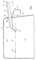
- a fuel tank 1 for a vehicle in particular for a passenger car, which is constructed in plastic or sheet metal construction.
- the fuel tank 1 is held in position in a manner not shown via conventional fastening elements on the body.
- Adjacent to the fuel tank 1 extends a body or chassis part 2, the upper edge 3 of which defines a horizontal plane AA.
- the body or chassis part 2 is formed by a longitudinal hollow beam. Due to the height extension of the hollow support, the entry point 4 of a filler neck 5 runs relatively high on the fuel tank 1.
- the end 8 of the filler neck 5 projecting into the container interior 7 and a refueling vent 9, 10 extend below a plane AA defined by the upper edge 3 of the adjacent body or chassis part 2.
- the maximum filling height H is determined by the highest point of the free end of the refueling ventilation 9, 10 located in the container interior 7.
- the free end 8 of the filler neck 5 runs at most at the level of the fill level H or lower.
- Fig. 1 shows a fuel tank with a filler neck 5 attached to it and an internal refueling vent 9, ie a vent pipe 11 of the Refueling ventilation 9 runs inside the filler neck 5 and in an upper area thereof.
- the filler neck 5 is fastened by means of a radial collar 12 to the outside of a side fuel tank wall 13 by welding, gluing or the like and projects with a section 14 through an opening 15 in the fuel tank wall 13 into the tank interior 7.
- the free end 8 of the section 14, which is of an angular or arcuate configuration, is directed downward, specifically in the direction of the bottom of the fuel tank 1.
- the section 14 is composed of two sections which are arranged at an angle and are connected to one another via a curved transition area.
- the free ends of the refueling ventilation 9 and the filler neck 5 lie below the plane A-A, the maximum filling height H being determined by the highest point from which displaced air can escape through the ventilation pipe 11.
- the free end 8 of the filler neck 5 is somewhat lower than the maximum fill height H.
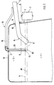
- Fig. 2 differs from Fig. 1 in that an external refueling vent 10 is provided.
- a vent pipe 16 extends outside the filler neck 5 and is guided through an opening 17 in the upper fuel tank wall 18 into the tank interior 7.
- the lower, horizontally running end 19 of the section 20 of the ventilation pipe 16 projecting into the interior of the container defines the maximum filling height H, which is also below the plane A-A.
- the free end 8 of the filler neck 5 is slightly lower than the plane A-A.
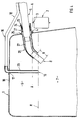
- FIG. 3 shows a particularly advantageous type of embodiment.
- the filler neck 5 is designed as a “plugged filler neck”, ie it is retrofitted to the vehicle with the fuel tank 1 already installed.
- an internal refueling vent 9 is also provided.
- a tubular receptacle 21 is arranged on the fuel tank 1, through which the filler neck 5 is passed in some areas.
- the filler neck 5 projects beyond the receiving neck 21 within the container interior 7 by a dimension B.
- a sealing element 22 is provided between filler neck 5 and receiving neck 21, which is held in position on the receiving neck 21 according to the exemplary embodiment.
- the sealing element 22 is pushed onto a wavy receiving section of an inner cylindrical leg of a sleeve 23.
- An outer leg of the sleeve 23 is guided around the free end of the outer receptacle 21 and connected to the receptacle 21 via a flange connection 24.
- the section of the receptacle 21 lying outside the fuel tank 1 is supported by a radial collar 25 on the outside of the fuel tank 1 and is fastened there. Adjacent to the collar 25, the receptacle 21 has a second, curved guide section 26 which extends downward and extends within the fuel tank 1.
- the filler neck 5 is provided, at least in sections, with a flexible section 27 in the region of the arcuate or angular guide section 26.
- the ventilation pipe 11 running within the filler neck 5 also has a flexible section 28 in sections.
- the flexible sections 27, 28 of filler neck 5 and ventilation pipe 11 are each formed by a flexible corrugated pipe (for example made of PA) or a flexible rubber part.
- the flexible sections 27, 28 form intermediate pieces of the filler neck 5 and the vent pipe 11.
- the intermediate pieces connect straight sections of the filler neck 5 and the vent pipe 11 with straight, short end pieces of the filler neck 5 and the vent pipe 11.
- the flexible sections 27, 28 form end regions of the filler neck 5 or the vent pipe 11.
- the filler neck 5 and the ventilation pipe 11 have a straight shape in the delivery state. Only when it is introduced into the fuel tank 1 are the filler neck 5 and the ventilation pipe 11 bent downward by the outer guide section 26 of the receiving neck 21 and have a curved shape, at least in sections. According to FIG. 3, the maximum filling height H is defined by the highest point of the inner refueling ventilation 9 arranged inside the container interior 7.
- Fig. 4 is essentially identical to Fig. 3, only instead of the internal refueling vent 9 is an external refueling vent 10 according to. Fig. 2 is provided.
- the fill level in FIG. 2 can be reduced from H to H1.
- the extensions are shown in dash-dot lines.
Landscapes
- Engineering & Computer Science (AREA)
- Life Sciences & Earth Sciences (AREA)
- Sustainable Development (AREA)
- Sustainable Energy (AREA)
- Chemical & Material Sciences (AREA)
- Combustion & Propulsion (AREA)
- Transportation (AREA)
- Mechanical Engineering (AREA)
- Cooling, Air Intake And Gas Exhaust, And Fuel Tank Arrangements In Propulsion Units (AREA)
Applications Claiming Priority (2)
| Application Number | Priority Date | Filing Date | Title |
|---|---|---|---|
| DE19532988 | 1995-09-07 | ||
| DE19532988A DE19532988C1 (de) | 1995-09-07 | 1995-09-07 | Kraftstoffbehälter für Fahrzeuge, insbesondere Personenkraftwagen |
Publications (3)
| Publication Number | Publication Date |
|---|---|
| EP0788916A2 true EP0788916A2 (fr) | 1997-08-13 |
| EP0788916A3 EP0788916A3 (fr) | 1998-04-15 |
| EP0788916B1 EP0788916B1 (fr) | 2000-03-22 |
Family
ID=7771462
Family Applications (1)
| Application Number | Title | Priority Date | Filing Date |
|---|---|---|---|
| EP96112103A Expired - Lifetime EP0788916B1 (fr) | 1995-09-07 | 1996-07-26 | Réservoir de carburant pour véhicules, en particulier pour voitures automobiles |
Country Status (5)
| Country | Link |
|---|---|
| US (1) | US5954367A (fr) |
| EP (1) | EP0788916B1 (fr) |
| JP (1) | JPH09104246A (fr) |
| KR (1) | KR100412291B1 (fr) |
| DE (2) | DE19532988C1 (fr) |
Families Citing this family (13)
| Publication number | Priority date | Publication date | Assignee | Title |
|---|---|---|---|---|
| JP2003182636A (ja) * | 2001-12-18 | 2003-07-03 | Fuji Heavy Ind Ltd | ピックアップトラックの車体後部構造 |
| CA2425462C (fr) * | 2002-04-11 | 2011-08-16 | Leroy G. Hagenbuch | Citerne cloisonnee pour vehicule |
| DE10234105B4 (de) * | 2002-07-26 | 2006-01-26 | Daimlerchrysler Ag | Flüssigkeitsbehälter für Fahrzeuge |
| FR2844486B1 (fr) * | 2002-09-13 | 2005-05-13 | Inergy Automotive Systems Res | Dispositif d'etancheite et de securite pour le remplissage d'un corps creux avec un liquide |
| DE102004024950A1 (de) * | 2004-05-21 | 2005-12-15 | Bayerische Motoren Werke Ag | Flüssigkeitsbehälter zur Anordnung in einem Hohlraum eines Aufbaus eines Kraftfahrzeugs |
| DE102008036538A1 (de) * | 2008-08-06 | 2010-04-22 | Kautex Textron Gmbh & Co Kg | Kraftfahrzeug-Kraftstoffbehälter |
| FR2936837B1 (fr) * | 2008-10-03 | 2011-09-09 | Inergy Automotive Systems Res | Integration du tube d'aeration sur le tuyau de remplissage d'un reservoir de fluide de depollution pour gaz d'echappement |
| DE102010032219A1 (de) | 2010-07-26 | 2012-01-26 | Continental Automotive Gmbh | Wellrohr einer Kraftstoffleitung |
| DE102011118929A1 (de) * | 2011-11-21 | 2013-05-23 | Kautex Textron Gmbh & Co. Kg | Nebenflüssigkeitsbehälter für ein Kfz |
| JP5974496B2 (ja) * | 2012-01-20 | 2016-08-23 | 東京電力ホールディングス株式会社 | 油圧操作機器及び作動油劣化防止方法 |
| DE102012016084A1 (de) * | 2012-08-14 | 2014-05-15 | Illinois Tool Works Inc. | Führungseinrichtung für eine Kraftstoffzapfpistole |
| DE102013213068A1 (de) * | 2013-07-04 | 2015-01-08 | Volkswagen Aktiengesellschaft | Vorrichtung zur Speicherung einer Harnstofflösung |
| JP2017210033A (ja) * | 2016-05-23 | 2017-11-30 | ヤマハ発動機株式会社 | 燃料タンク |
Family Cites Families (9)
| Publication number | Priority date | Publication date | Assignee | Title |
|---|---|---|---|---|
| US1589500A (en) * | 1924-10-30 | 1926-06-22 | Asa A Wilcox | Liquid inlet and air vent for tanks |
| US3448892A (en) * | 1966-08-24 | 1969-06-10 | Arvin Ind Inc | Fuel tank filler tube |
| US4394925A (en) * | 1981-05-29 | 1983-07-26 | Ford Motor Company | Fuel tank-filler pipe particularly for motor vehicles |
| JPS6139628Y2 (fr) * | 1981-06-12 | 1986-11-13 | ||
| DE3243833C1 (de) * | 1982-11-26 | 1984-05-24 | Ford-Werke AG, 5000 Köln | Kraftstoffbehälter für Kraftfahrzeuge |
| SE464569B (sv) * | 1990-01-26 | 1991-05-13 | Volvo Ab | Anordning vid braensletankar |
| US5201547A (en) * | 1991-04-10 | 1993-04-13 | Toyota Jidosha Kabushiki Kaisha | Rear under body structure |
| US5373957A (en) * | 1993-11-08 | 1994-12-20 | Ford Motor Company | Low expulsion vent for an automotive fuel tank |
| JP2921548B2 (ja) * | 1993-12-24 | 1999-07-19 | 本田技研工業株式会社 | 蒸発燃料処理装置 |
-
1995
- 1995-09-07 DE DE19532988A patent/DE19532988C1/de not_active Expired - Fee Related
-
1996
- 1996-07-26 DE DE59604771T patent/DE59604771D1/de not_active Expired - Lifetime
- 1996-07-26 EP EP96112103A patent/EP0788916B1/fr not_active Expired - Lifetime
- 1996-08-27 JP JP8225648A patent/JPH09104246A/ja active Pending
- 1996-08-29 US US08/705,124 patent/US5954367A/en not_active Expired - Fee Related
- 1996-09-06 KR KR1019960038603A patent/KR100412291B1/ko not_active Expired - Lifetime
Also Published As
| Publication number | Publication date |
|---|---|
| DE59604771D1 (de) | 2000-04-27 |
| EP0788916A3 (fr) | 1998-04-15 |
| JPH09104246A (ja) | 1997-04-22 |
| EP0788916B1 (fr) | 2000-03-22 |
| US5954367A (en) | 1999-09-21 |
| KR100412291B1 (ko) | 2004-07-30 |
| KR970015135A (ko) | 1997-04-28 |
| DE19532988C1 (de) | 1996-12-19 |
Similar Documents
| Publication | Publication Date | Title |
|---|---|---|
| EP0788916B1 (fr) | Réservoir de carburant pour véhicules, en particulier pour voitures automobiles | |
| DE69809712T2 (de) | Treibstofftank für lastwagen | |
| DE602004005622T2 (de) | Brennstoffpumpenmodul und Montageverfahren | |
| EP0245613B1 (fr) | Réservoir de carburant pour véhicules automobiles avec un tuyau de remplissage | |
| EP0311756B1 (fr) | Support de bec de remplissage pour un réservoir de carburant de véhicule automobile | |
| DE102008011733A1 (de) | Kraftstoffbefüllvorrichtung | |
| DE19510821C2 (de) | Kraftstoffbehälter für Fahrzeuge, insbesondere Kraftfahrzeuge | |
| EP2489538B1 (fr) | Manchon de remplissage pour le réservoir de carburant d'un véhicule automobile doté d'une ouverture sélective | |
| EP0955199B1 (fr) | Réservoir de carburant | |
| DE102005051948B4 (de) | Vorrichtung zur Aufnahme von Seitenkräften bei einem Seitenaufprall eines Kraftfahrzeugs | |
| DE3121453C2 (de) | Kraftfahrzeug-Hinterradaufhängung, insbesondere Achsaufhängung für ein Fahrzeug mit Frontmotor und Vorderradantrieb | |
| DE69217451T2 (de) | Filter für Kraftstoffbehälter | |
| EP0703132B1 (fr) | Maítre-cylindre de frein | |
| EP1136299A2 (fr) | Système d'aération d'un réservoir de carburant | |
| EP2019079B1 (fr) | Buse de distribution automatique avec ramasse-gouttes | |
| DE3224943A1 (de) | Kraftstoffbehaelteranlage fuer kraftfahrzeuge, insbesondere omnibusse | |
| DE19732064C2 (de) | Deformationselement | |
| DE4311470A1 (de) | Be- und Entlüftungseinrichtung eines Fahrzeug-Kraftstofftanks | |
| DE3730567C2 (de) | Flüssigkeitspumpe | |
| EP0694499B1 (fr) | Dispositif de renvoi de tuyau pour station de distribution de carburant | |
| CH684305A5 (de) | Matratzenrahmen mit einem daran schwenkbar angeschlossenen Kopfteil. | |
| DE102005052072B3 (de) | Kraftstoffbehälter | |
| AT3651U1 (de) | Füllrohr für den kraftstofftank eines kraftfahrzeuges | |
| DE2418063A1 (de) | Tankverschluss fuer kraftfahrzeuge | |
| DE202022105442U1 (de) | Druckbehälter |
Legal Events
| Date | Code | Title | Description |
|---|---|---|---|
| PUAI | Public reference made under article 153(3) epc to a published international application that has entered the european phase |
Free format text: ORIGINAL CODE: 0009012 |
|
| AK | Designated contracting states |
Kind code of ref document: A2 Designated state(s): DE FR GB IT |
|
| PUAL | Search report despatched |
Free format text: ORIGINAL CODE: 0009013 |
|
| AK | Designated contracting states |
Kind code of ref document: A3 Designated state(s): DE FR GB IT |
|
| 17P | Request for examination filed |
Effective date: 19980429 |
|
| GRAG | Despatch of communication of intention to grant |
Free format text: ORIGINAL CODE: EPIDOS AGRA |
|
| GRAG | Despatch of communication of intention to grant |
Free format text: ORIGINAL CODE: EPIDOS AGRA |
|
| GRAH | Despatch of communication of intention to grant a patent |
Free format text: ORIGINAL CODE: EPIDOS IGRA |
|
| 17Q | First examination report despatched |
Effective date: 19990817 |
|
| GRAH | Despatch of communication of intention to grant a patent |
Free format text: ORIGINAL CODE: EPIDOS IGRA |
|
| ITF | It: translation for a ep patent filed | ||
| GRAA | (expected) grant |
Free format text: ORIGINAL CODE: 0009210 |
|
| AK | Designated contracting states |
Kind code of ref document: B1 Designated state(s): DE FR GB IT |
|
| REF | Corresponds to: |
Ref document number: 59604771 Country of ref document: DE Date of ref document: 20000427 |
|
| ET | Fr: translation filed | ||
| GBT | Gb: translation of ep patent filed (gb section 77(6)(a)/1977) |
Effective date: 20000623 |
|
| PLBE | No opposition filed within time limit |
Free format text: ORIGINAL CODE: 0009261 |
|
| STAA | Information on the status of an ep patent application or granted ep patent |
Free format text: STATUS: NO OPPOSITION FILED WITHIN TIME LIMIT |
|
| 26N | No opposition filed | ||
| REG | Reference to a national code |
Ref country code: GB Ref legal event code: IF02 |
|
| PGFP | Annual fee paid to national office [announced via postgrant information from national office to epo] |
Ref country code: IT Payment date: 20080726 Year of fee payment: 13 Ref country code: FR Payment date: 20080715 Year of fee payment: 13 |
|
| PGFP | Annual fee paid to national office [announced via postgrant information from national office to epo] |
Ref country code: GB Payment date: 20080722 Year of fee payment: 13 |
|
| REG | Reference to a national code |
Ref country code: FR Ref legal event code: TP |
|
| REG | Reference to a national code |
Ref country code: FR Ref legal event code: CD |
|
| GBPC | Gb: european patent ceased through non-payment of renewal fee |
Effective date: 20090726 |
|
| REG | Reference to a national code |
Ref country code: FR Ref legal event code: ST Effective date: 20100331 |
|
| PG25 | Lapsed in a contracting state [announced via postgrant information from national office to epo] |
Ref country code: FR Free format text: LAPSE BECAUSE OF NON-PAYMENT OF DUE FEES Effective date: 20090731 |
|
| PG25 | Lapsed in a contracting state [announced via postgrant information from national office to epo] |
Ref country code: GB Free format text: LAPSE BECAUSE OF NON-PAYMENT OF DUE FEES Effective date: 20090726 |
|
| PG25 | Lapsed in a contracting state [announced via postgrant information from national office to epo] |
Ref country code: IT Free format text: LAPSE BECAUSE OF NON-PAYMENT OF DUE FEES Effective date: 20090726 |
|
| PGFP | Annual fee paid to national office [announced via postgrant information from national office to epo] |
Ref country code: DE Payment date: 20140711 Year of fee payment: 19 |
|
| REG | Reference to a national code |
Ref country code: DE Ref legal event code: R119 Ref document number: 59604771 Country of ref document: DE |
|
| PG25 | Lapsed in a contracting state [announced via postgrant information from national office to epo] |
Ref country code: DE Free format text: LAPSE BECAUSE OF NON-PAYMENT OF DUE FEES Effective date: 20160202 |