EP0790438A1 - Entraînement à croix de Malte - Google Patents
Entraînement à croix de Malte Download PDFInfo
- Publication number
- EP0790438A1 EP0790438A1 EP97102217A EP97102217A EP0790438A1 EP 0790438 A1 EP0790438 A1 EP 0790438A1 EP 97102217 A EP97102217 A EP 97102217A EP 97102217 A EP97102217 A EP 97102217A EP 0790438 A1 EP0790438 A1 EP 0790438A1
- Authority
- EP
- European Patent Office
- Prior art keywords
- drive mechanism
- geneva drive
- cam
- slots
- driving member
- Prior art date
- Legal status (The legal status is an assumption and is not a legal conclusion. Google has not performed a legal analysis and makes no representation as to the accuracy of the status listed.)
- Granted
Links
Images

Classifications
-
- F—MECHANICAL ENGINEERING; LIGHTING; HEATING; WEAPONS; BLASTING
- F16—ENGINEERING ELEMENTS AND UNITS; GENERAL MEASURES FOR PRODUCING AND MAINTAINING EFFECTIVE FUNCTIONING OF MACHINES OR INSTALLATIONS; THERMAL INSULATION IN GENERAL
- F16H—GEARING
- F16H27/00—Step-by-step mechanisms without freewheel members, e.g. Geneva drives
- F16H27/04—Step-by-step mechanisms without freewheel members, e.g. Geneva drives for converting continuous rotation into a step-by-step rotary movement
- F16H27/06—Mechanisms with driving pins in driven slots, e.g. Geneva drives
-
- Y—GENERAL TAGGING OF NEW TECHNOLOGICAL DEVELOPMENTS; GENERAL TAGGING OF CROSS-SECTIONAL TECHNOLOGIES SPANNING OVER SEVERAL SECTIONS OF THE IPC; TECHNICAL SUBJECTS COVERED BY FORMER USPC CROSS-REFERENCE ART COLLECTIONS [XRACs] AND DIGESTS
- Y10—TECHNICAL SUBJECTS COVERED BY FORMER USPC
- Y10T—TECHNICAL SUBJECTS COVERED BY FORMER US CLASSIFICATION
- Y10T74/00—Machine element or mechanism
- Y10T74/14—Rotary member or shaft indexing, e.g., tool or work turret
- Y10T74/1418—Preselected indexed position
- Y10T74/1424—Sequential
- Y10T74/1441—Geneva or mutilated gear drive
-
- Y—GENERAL TAGGING OF NEW TECHNOLOGICAL DEVELOPMENTS; GENERAL TAGGING OF CROSS-SECTIONAL TECHNOLOGIES SPANNING OVER SEVERAL SECTIONS OF THE IPC; TECHNICAL SUBJECTS COVERED BY FORMER USPC CROSS-REFERENCE ART COLLECTIONS [XRACs] AND DIGESTS
- Y10—TECHNICAL SUBJECTS COVERED BY FORMER USPC
- Y10T—TECHNICAL SUBJECTS COVERED BY FORMER US CLASSIFICATION
- Y10T74/00—Machine element or mechanism
- Y10T74/18—Mechanical movements
- Y10T74/18528—Rotary to intermittent unidirectional motion
-
- Y—GENERAL TAGGING OF NEW TECHNOLOGICAL DEVELOPMENTS; GENERAL TAGGING OF CROSS-SECTIONAL TECHNOLOGIES SPANNING OVER SEVERAL SECTIONS OF THE IPC; TECHNICAL SUBJECTS COVERED BY FORMER USPC CROSS-REFERENCE ART COLLECTIONS [XRACs] AND DIGESTS
- Y10—TECHNICAL SUBJECTS COVERED BY FORMER USPC
- Y10T—TECHNICAL SUBJECTS COVERED BY FORMER US CLASSIFICATION
- Y10T74/00—Machine element or mechanism
- Y10T74/19—Gearing
- Y10T74/1987—Rotary bodies
- Y10T74/19879—Geneva
Definitions
- This invention relates to a Geneva drive mechanism including a driven member defining arcuate recesses and radially outwardly opening slots arranged in a rotating direction, and a driving member having an engaging element for engaging the slots of the driven member to rotate the driven member intermittently by a predetermined angle.
- the Geneva drive mechanism has a function to convert continuous rotation into intermittent rotation by a set angle. That is, when a continuous rotation is inputted, the Geneva drive mechanism outputs an alternate repetition of rotation and stoppage, i.e. a rotation through a set angle followed by a stopping period, and then a rotation through the same set angle.
- this type of Geneva drive mechanism includes a driven member defining arcuate recesses and radially outwardly opening slots arranged alternately at predetermined intervals circumferentially of the driven member, and a driving member for intermittently rotating the driven member.
- a Geneva drive mechanism is disclosed in Japanese Utility Model Publications Kokai No. S60-64357 and No. H6-40507, for example.
- the driving member includes an engaging roller acting as the engaging element for successively engaging a plurality of slots in the driven member to rotate the driven member intermittently by a predetermined angle.
- This driving member further includes a plurality of turn rollers rotatable about pivotal axes fixed to the driving member for contacting arcuate surfaces of the arcuate recesses in the driven member when the engaging roller is disengaged from the slots so that the driven member does not rotate with the driving member.
- the turn rollers of the driving member With the driven member at rest, the turn rollers of the driving member, while contacting the arcuate surface of one of the arcuate recesses of the driven member, rotate about the pivotal axes and move with the driving member along the arcuate surface.
- the driving member may include a cam defining a rotation restricting surface movable in sliding contact with the arcuate surfaces of the arcuate recesses of the driven member at rest (see Fig. 4 of Japanese Utility Model Publications Kokai No. H6-40507, for example).
- the foregoing construction has an advantage of reducing friction between the driving member and the driven member when the latter is at rest during intermittent rotation. With the reduced friction, the driving member is smoothly rotatable free of Seizure, the Geneva drive mechanism has an extended life, and a reduction in energy consumption may be achieved in relation to rotation of the driving member itself.
- This invention has been made having regard to the state of the art noted above, and its object is to provide a Geneva drive mechanism with an improved structure for supporting rolling elements arranged on the driving member, thereby to promote an extended life and energy saving compared with the prior art.
- a Geneva drive mechanism including, instead of the rollers rotatable about pivotal axes fixed to the driving member, rolling elements arranged in an annular groove to be rotatable and movable circumferentially of the driving member.
- the rolling elements mounted in the annular groove formed in the cam of the driving member rotate and move along the annular groove while in contact with the arcuate surface of one of the arcuate recesses of the driven member.
- This movement of the rolling elements has the effect of reducing friction between the driving member and driven member.
- the driving member may be driven smoothly without seizure and chattering.
- the Geneva drive mechanism has an extended life and energy saving may be promoted.
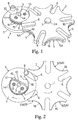
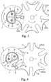
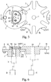
- a Geneva drive mechanism in a preferred embodiment shown in Figs. 1 through 7 includes a driven member 2 having an output shaft 1, and a driving member 4 having an input shaft 3 for intermittently rotating the driven member 2.
- These rotatable members 2 and 4 are rotatably supported by a fixed frame (not shown) through the output shaft 1 and input shaft 3. As seen, the output shaft 1 and input shaft 3 extend parallel to each other.
- Radial directions and circumferential direction of the driven member 2 are defined as directions extending toward the above shafts in planes perpendicular to the axial directions, and a direction perpendicular to the radial directions, respectively.
- Radial directions and circumferential direction of the driving member 4 are defined likewise.
- intermittent rotation means a continuous rotation through a predetermined angle followed by a rotation for a set time or a repetition thereof.
- the input shaft 3 is rotatable by a drive system D having a drive actuator such as an electric motor or hydraulic motor. Torque output of the drive system D is transmitted to the driving member 4 through the input shaft 3 to rotate the driving member 4.
- the driving member 4 intermittently rotates the driven member 2, which is transmitted through the output shaft 1 to an input E of a processing apparatus or the like.
- a Geneva drive mechanism is useful, for example, in repeating the same process at each set angle circumferentially of a cylindrical object.
- the Geneva drive mechanism has wide application without being limited to the above example.
- the driven member 2 defines arcuate recesses 5 of identical shape and radially outwardly opening slots 6 arranged alternately in the circumferential direction thereof.
- the arcuate recesses 5 have central portions thereof situated close to the output shaft 1 of the driven member 2.
- Each slot 6 is U-shaped and extends radially inwardly from an opening formed peripherally of the driven member 2, with inner surfaces thereof defining an opposed pair of guide surfaces.
- the arcuate recesses 5 and slots 6 are provided six each.
- the driven member 2 has the output shaft 1 fixed in a bore 2a formed centrally thereof.
- the driven member 2 is called a Geneva gear hereinafter.
- the Geneva gear 2 is formed of high carbon chrome bearing steel, and peripheral portions of the arcuate recesses 5 have been quenched.
- the high carbon chrome bearing steel preferably has chemical ingredients based on SUJ2 of the Japanese Industrial Standards (JIS). Specifically, as preferred chemical ingredients of the high carbon chrome bearing steel used in this embodiment, C is contained in 0.95 - 1.10%, Si in 0.15 - 0.35%, Mn in 0.50% or less, P in 0.025% or less, S in 0.025% or less, and Cr in 1.30 - 1.60%. Mo must not exceed 0.08%. Other elements may be added in 0.25% or less.
- the driving member 4 includes a disk-shaped base 7.
- One engaging roller 8 is rotatably supported in a peripheral position on one surface of the base 7 to act as an engaging element for successively engaging the six slots 6 in the Geneva gear 2. Since the Geneva gear 2 has six slots 6, the Geneva gear 2 is intermittently rotatable at the set angle of 60 degrees by engagement between the engaging element of driving member 4 and these slots 6.
- a peripheral portion of the base 7 overlaps the Geneva gear 2 when seen in the axial direction.
- a cam 11 is mounted in a central portion on the one surface of the base 7.
- the cam 11 defines an arcuate rotation restricting surface 9 which is movable relative to and along an arcuate surface 5A of one of the arcuate recesses 5 of Geneva gear 2 when the Geneva gear 2 stops in intermittent rotation, with the engaging roller 8 disengaged from the slots 6.
- the state in which the engaging element 8 engages one of the slots 6 in the driven member 2 whereby the driven member 2 rotates with the driving member 4 is called the first state.
- the state in which the engaging element 8 is disengaged from the slots 6 and the driven member 2 stands still while the driving member 4 is in rotation is called the second state.
- the cam 11 defines a relative rotation permitting surface 10 which is out of contact with the Geneva gear 2 to permit rotation of the Geneva gear 2 in the first state in which the engaging roller 8 is engaged with one of the slots 6.
- the driving member 4 has a bore 4a formed in a central portion thereof and extending through the base 7 and cam 11, and the input shaft 3 is fixed in the bore 4a.
- the base 7 and the cam 11 constituting the driving member 4 are formed of high carbon chrome bearing steel (SUJ2).
- the rotation restricting surface 9 of the cam 11 is formed of an arcuate surface of approximately 255-degree range around a rotational axis of the base 7.
- the rotation restricting surface 9 has a slightly smaller radius than each arcuate recess 5 of Geneva gear 2.
- the relative rotation permitting surface 10 of the cam 11 is continuous with opposite ends in the circumferential direction of the rotation restricting surface 9, and opposed to the rotation restricting surface 9 across the rotational axis.
- the relative rotation permitting surface 10 includes a straight surface extending through an intermediate range thereof and opposed to the engaging roller 8.
- the cam 11 as a whole is D-shaped as seen in the axial direction, which is formed by the arcuate rotation restricting surface 9 and the substantially straight relative rotation permitting surface 10.
- the cam 11 has a split structure including a first cam member 11A formed integral with the base 7, and a second cam member 11B fitted in the direction of the rotational axis in the first cam member 11A and tightened thereto with a pair of bolts 13.
- the first cam member 11A defines a recess for receiving the second cam member 11B.
- grooves 15A and 15B for forming an annular groove 15 acting as a rolling element guide for holding a plurality of rolling elements 14 to be rotatable and movable circumferentially of the driving member 4.
- balls 14 formed of high carbon chrome bearing steel (SUJ2) are used as the rolling elements 14.
- the annular groove 15 has an arcuate section corresponding to the shape of balls 14 acting as the rolling elements.
- the annular groove 15 has a continuous, semicircular form extending along the rotation restricting surface 9 and relative rotation permitting surface 10 as seen in the axial direction.
- the annular groove 15 opens radially outwardly in the region of the rotation restricting surface 9. Consequently, the balls 14 protrude radially outwardly from the rotation restricting surface 9 of the cam 11 to contact the arcuate surface 5A of one of the arcuate recesses 5 of Geneva gear 2 in the second state in which the Geneva gear 2 stops during intermittent rotation.
- the annular groove 15 has an opening width in the axial direction smaller than the diameter of balls 14, so that the balls 14 never fall out of the annular groove 15 through this opening.
- the annular groove 15 is in the form of a straight tunnel through the cam 11 in the region of the relative rotation permitting surface 10. Consequently, the balls 14 are completely contained in the cam 11 in the region of the relative rotation permitting surface 10 instead of being exposed to the outside.
- each arcuate recess 5 of Geneva gear 2 includes a guide groove 16 extending through an entire circumferential length thereof to be opposed to the balls 14 acting as the rolling elements exposed from the rotation restricting surface 9.
- the guide groove 16 has an arcuate section corresponding to the section of balls 14. Thus, the balls 14 and guide groove 16 make an arcuate contact with each other.
- the rotation restricting surface 9 of the cam 11 lies close and opposed to at least a half length in the circumferential direction of the arcuate surface 5A of the Geneva gear 2, and the balls 14 arranged in the annular groove 15 of the cam 11 and exposed from the rotation restricting surface 9 contact the guide groove 16 formed in the arcuate surface 5A of the Geneva gear 2, thereby restricting forward and backward rotations of the Geneva gear 2.
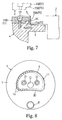
- Fig. 8 shows another embodiment of the driving member 4 modified from the first embodiment.
- the cam 11 of the driving member 4 is chamfered to arcuate shape at transitional portions between rotation restricting surface 9 and relative rotation permitting surface 10.
- the balls 14 acting as the rolling elements mounted in the annular groove 15 of the cam 11 to be rotatable and movable circumferentially of the driving member 4 may be exposed to the outside over the entire circumference of rotation restricting surface 9 and relative rotation permitting surface 10.
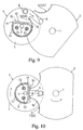
- Figs. 9 through 11 show a Geneva drive mechanism in a further embodiment of this invention.
- the Geneva gear 2 acting as the driven member has, arranged in the rotating direction, one slot 6 cut in U-shape opening radially outwardly and two arcuate recesses 5 of identical shape opposed to each other across the slot 6.
- the driving member 4 is reciprocable by the drive system D between a position immediately before the engaging roller 8 rotatably supported by the driving member 4 engages the slot 6 in the Geneva gear 2 and a position immediately after the engaging roller 8 disengages from the slot 6 of Geneva gear 2.
- the other aspects are the same as in the foregoing preferred embodiment.
- the engaging roller 8 of the driving member 4 engages the slot 6 of Geneva gear 2 to rotate the Geneva gear 2 in one direction.
- the rotation restricting surface 9 of the cam 11 of the driving member 4 slightly rotates relative to the arcuate surface 5A of one of the arcuate recesses 5 of Geneva gear 2 standing still. Then the driving member 4 is stopped.
- the drive system D rotates the driving member 4 in the opposite direction.
- the engaging roller 8 engages the slot 6 of Geneva gear 2 to rotate the Geneva gear 2 in the opposite direction.
- the rotation restricting surface 9 of the cam 11 of the driving member 4 slightly rotates relative to the arcuate surface 5A of the other arcuate recess 5 of Geneva gear 2 standing still. Then the driving member 4 is stopped
- the Geneva gear 2 is reliably rotated reciprocally through a fixed stroke.
Landscapes
- Engineering & Computer Science (AREA)
- General Engineering & Computer Science (AREA)
- Mechanical Engineering (AREA)
- Transmission Devices (AREA)
Applications Claiming Priority (3)
| Application Number | Priority Date | Filing Date | Title |
|---|---|---|---|
| JP8030247A JP2788218B2 (ja) | 1995-06-01 | 1996-02-19 | ゼネバ歯車機構 |
| JP3024796 | 1996-02-19 | ||
| JP30247/96 | 1996-02-19 |
Publications (2)
| Publication Number | Publication Date |
|---|---|
| EP0790438A1 true EP0790438A1 (fr) | 1997-08-20 |
| EP0790438B1 EP0790438B1 (fr) | 2000-04-26 |
Family
ID=12298390
Family Applications (1)
| Application Number | Title | Priority Date | Filing Date |
|---|---|---|---|
| EP97102217A Expired - Lifetime EP0790438B1 (fr) | 1996-02-19 | 1997-02-12 | Entraínement à croix de Malte |
Country Status (5)
| Country | Link |
|---|---|
| US (1) | US5906134A (fr) |
| EP (1) | EP0790438B1 (fr) |
| KR (1) | KR970062410A (fr) |
| CN (1) | CN1165926A (fr) |
| DE (1) | DE69701756T2 (fr) |
Cited By (2)
| Publication number | Priority date | Publication date | Assignee | Title |
|---|---|---|---|---|
| EP1054189A1 (fr) * | 1999-05-20 | 2000-11-22 | Sang Wan Joo | Came d'entraínement d'un entraínement à croix de Malte |
| EP1895194A3 (fr) * | 2006-08-31 | 2011-12-21 | Robert Bosch Gmbh | Interface d'entraînement |
Families Citing this family (21)
| Publication number | Priority date | Publication date | Assignee | Title |
|---|---|---|---|---|
| JP3278382B2 (ja) * | 1997-08-01 | 2002-04-30 | 山田エンジニアリング株式会社 | 間欠伝動機構 |
| KR100428730B1 (ko) * | 1999-03-23 | 2004-04-28 | 가가쿠 기쥬츠 신코 지교단 | 간헐 전동 장치 |
| US6503123B2 (en) * | 1999-12-30 | 2003-01-07 | Toyinnovation Inc | Toys incorporating geneva gear assemblies |
| EP1479625B1 (fr) * | 2003-05-20 | 2006-09-06 | Müller Martini Holding AG | Dispositif pour alimenter une ligne de transformation |
| CN102777560A (zh) * | 2012-08-26 | 2012-11-14 | 温州名瑞机械有限公司 | 一种八齿外接槽轮机构 |
| CN103174920A (zh) * | 2013-03-15 | 2013-06-26 | 天津市亚安科技股份有限公司 | 一种应用于视频监控系统的云台 |
| CN104251293B (zh) * | 2013-06-30 | 2017-06-06 | 郭伟 | 双轮驱动间歇旋转工作台 |
| CN105480905A (zh) * | 2016-01-06 | 2016-04-13 | 潘玲玉 | 一种槽轮驱动推动装置 |
| CN106042053B (zh) * | 2016-07-13 | 2018-11-06 | 泉州市科茂利通智能科技有限公司 | 一种多功能平面打孔机 |
| CN106476033A (zh) * | 2016-12-21 | 2017-03-08 | 北京灵铱科技有限公司 | 一种间歇转动机器人头部装置 |
| GB201710959D0 (en) * | 2017-07-07 | 2017-08-23 | Eaton Srl | Actuator arrangement |
| DE102018113535B4 (de) * | 2018-06-06 | 2023-03-09 | Lange Uhren Gmbh | Antriebseinrichtung |
| CN108973367B (zh) * | 2018-09-03 | 2020-06-19 | 安徽省皖太电器有限公司 | 一种用于纽扣电子表面加工的旋转装置 |
| KR20240158376A (ko) * | 2018-10-03 | 2024-11-04 | 콘메드 코포레이션 | 스스로 잠김, 다중-위치, 및 슬라이드 버튼에 의해 선형으로 작동되는 집어넣을 수 있는 블래이드 또는 후크를 갖는 부드러운 조직 절단 도구 |
| CN109604574B (zh) * | 2018-10-24 | 2020-10-20 | 广德亚太汽车智能制动系统有限公司 | 一种间歇式传动组件及其应用的浇包倾倒装置 |
| CN109435554B (zh) * | 2018-12-07 | 2024-03-08 | 珠海格力智能装备有限公司 | 换刀装置及具有其的雕刻机 |
| CA3165829A1 (fr) * | 2020-02-12 | 2021-08-19 | Raja Ramanujam Rajendran | Transmission a variation infinie a rapport entree-sortie uniforme qui n'est pas dependante du frottement |
| KR20260040358A (ko) * | 2020-06-08 | 2026-03-24 | 라자 라마누잠 라젠드란 | 인터럽트 없는 변속을 가지는 의사 무단 변속기 |
| CN112723116A (zh) * | 2021-01-14 | 2021-04-30 | 湖州富机电梯有限公司 | 一种用于家用电梯的门机 |
| FR3128599B1 (fr) * | 2021-10-22 | 2023-10-13 | Nexans | Agencement d’entraînement de type croix de Malte et suiveur solaire comportant un tel agencement |
| CN114571257B (zh) * | 2022-02-12 | 2023-04-28 | 徐州鹏宇液压科技有限公司 | 一种智能控制型加工中心 |
Citations (4)
| Publication number | Priority date | Publication date | Assignee | Title |
|---|---|---|---|---|
| US3855873A (en) * | 1973-11-02 | 1974-12-24 | Nasa | Geneva mechanism |
| JPS6064357U (ja) | 1983-10-12 | 1985-05-07 | 川村 甚栄 | 高速回転用ゼネバ歯車機構 |
| SU1216516A1 (ru) * | 1984-09-03 | 1986-03-07 | Минское Высшее Инженерное Зенитное Ракетное Училище Противовоздушной Обороны | Мальтийский механизм |
| JPH0640507U (ja) | 1992-11-04 | 1994-05-31 | シ−クアン・チエン | ゼネバ式ストップ装置の改良構造体 |
Family Cites Families (5)
| Publication number | Priority date | Publication date | Assignee | Title |
|---|---|---|---|---|
| DE36595C (de) * | METALL-WERKE, VORM. J. ADERS in Neustadt-Magdeburg | Neuerung an stehenden Verdampfapparaten für Zucker- und andere Säfte | ||
| DE322225C (de) * | 1920-06-23 | Hermann Maler | Schaltscheibe fuer das Malteserkreuz | |
| JPS5631525A (en) * | 1979-08-23 | 1981-03-30 | Nippon Seiko Kk | Ball bearing |
| JPS6064357A (ja) * | 1983-09-20 | 1985-04-12 | Fuji Electric Co Ltd | 電子写真用セレン感光体 |
| JP2556199B2 (ja) * | 1992-07-10 | 1996-11-20 | 村田機械株式会社 | 昇降台の荷姿検出装置 |
-
1997
- 1997-02-12 US US08/799,398 patent/US5906134A/en not_active Expired - Fee Related
- 1997-02-12 DE DE69701756T patent/DE69701756T2/de not_active Expired - Fee Related
- 1997-02-12 EP EP97102217A patent/EP0790438B1/fr not_active Expired - Lifetime
- 1997-02-19 KR KR1019970004949A patent/KR970062410A/ko not_active Withdrawn
- 1997-02-19 CN CN97102541A patent/CN1165926A/zh active Pending
Patent Citations (4)
| Publication number | Priority date | Publication date | Assignee | Title |
|---|---|---|---|---|
| US3855873A (en) * | 1973-11-02 | 1974-12-24 | Nasa | Geneva mechanism |
| JPS6064357U (ja) | 1983-10-12 | 1985-05-07 | 川村 甚栄 | 高速回転用ゼネバ歯車機構 |
| SU1216516A1 (ru) * | 1984-09-03 | 1986-03-07 | Минское Высшее Инженерное Зенитное Ракетное Училище Противовоздушной Обороны | Мальтийский механизм |
| JPH0640507U (ja) | 1992-11-04 | 1994-05-31 | シ−クアン・チエン | ゼネバ式ストップ装置の改良構造体 |
Non-Patent Citations (1)
| Title |
|---|
| DATABASE WPI Week 8644, Derwent World Patents Index; AN 86-290233, XP002032226 * |
Cited By (2)
| Publication number | Priority date | Publication date | Assignee | Title |
|---|---|---|---|---|
| EP1054189A1 (fr) * | 1999-05-20 | 2000-11-22 | Sang Wan Joo | Came d'entraínement d'un entraínement à croix de Malte |
| EP1895194A3 (fr) * | 2006-08-31 | 2011-12-21 | Robert Bosch Gmbh | Interface d'entraînement |
Also Published As
| Publication number | Publication date |
|---|---|
| KR970062410A (ko) | 1997-09-12 |
| EP0790438B1 (fr) | 2000-04-26 |
| US5906134A (en) | 1999-05-25 |
| DE69701756T2 (de) | 2000-09-07 |
| CN1165926A (zh) | 1997-11-26 |
| DE69701756D1 (de) | 2000-05-31 |
Similar Documents
| Publication | Publication Date | Title |
|---|---|---|
| EP0790438B1 (fr) | Entraínement à croix de Malte | |
| CA1227953A (fr) | Entrainement antifriction pour outil a visser | |
| US5115159A (en) | Built-in generator for bicycle | |
| US9145919B2 (en) | Speed-reduction transmission bearing | |
| JP3278382B2 (ja) | 間欠伝動機構 | |
| JP2788218B2 (ja) | ゼネバ歯車機構 | |
| US6684728B2 (en) | Rectilinear motion driving apparatus | |
| US6270442B1 (en) | Multi-function speed converter | |
| US20250075778A1 (en) | Ball screw device | |
| US20210140489A1 (en) | Spline structure, speed-reducing or -increasing apparatus, and constant-velocity joint | |
| JP2661789B2 (ja) | ボールねじ | |
| JP3287688B2 (ja) | ボールスプライン | |
| JPH07317869A (ja) | 直線駆動装置 | |
| JP3424560B2 (ja) | トロイダル型無段変速機用入力側ディスクユニット | |
| JPS6116440Y2 (fr) | ||
| JP7858022B1 (ja) | 軸受け装置及び歯車装置 | |
| JPS62246644A (ja) | 動力伝動装置 | |
| JP2021179252A (ja) | 軸受のインナレース、回転機器、及び、減速機 | |
| JPS5923864Y2 (ja) | トリポ−ドジヨイント | |
| US11754163B1 (en) | Strain wave generator for harmonic reducer | |
| JP2003139135A (ja) | リニアブッシュ及びリニアブッシュ用軌道軸 | |
| JPS6246045A (ja) | 減速装置及び減速ギヤドモ−タ | |
| EP4249770A1 (fr) | Générateur d'ondes de déformation pour réducteur d'harmonique | |
| JP3166057B2 (ja) | 同軸型減速機 | |
| JP4182593B2 (ja) | トロイダル型無段変速機用入力側ディスクユニット |
Legal Events
| Date | Code | Title | Description |
|---|---|---|---|
| PUAI | Public reference made under article 153(3) epc to a published international application that has entered the european phase |
Free format text: ORIGINAL CODE: 0009012 |
|
| AK | Designated contracting states |
Kind code of ref document: A1 Designated state(s): DE FR GB |
|
| 17P | Request for examination filed |
Effective date: 19980217 |
|
| GRAG | Despatch of communication of intention to grant |
Free format text: ORIGINAL CODE: EPIDOS AGRA |
|
| 17Q | First examination report despatched |
Effective date: 19990623 |
|
| GRAG | Despatch of communication of intention to grant |
Free format text: ORIGINAL CODE: EPIDOS AGRA |
|
| GRAH | Despatch of communication of intention to grant a patent |
Free format text: ORIGINAL CODE: EPIDOS IGRA |
|
| GRAH | Despatch of communication of intention to grant a patent |
Free format text: ORIGINAL CODE: EPIDOS IGRA |
|
| GRAA | (expected) grant |
Free format text: ORIGINAL CODE: 0009210 |
|
| AK | Designated contracting states |
Kind code of ref document: B1 Designated state(s): DE FR GB |
|
| REF | Corresponds to: |
Ref document number: 69701756 Country of ref document: DE Date of ref document: 20000531 |
|
| ET | Fr: translation filed | ||
| PGFP | Annual fee paid to national office [announced via postgrant information from national office to epo] |
Ref country code: FR Payment date: 20010112 Year of fee payment: 5 |
|
| PGFP | Annual fee paid to national office [announced via postgrant information from national office to epo] |
Ref country code: GB Payment date: 20010207 Year of fee payment: 5 |
|
| PLBE | No opposition filed within time limit |
Free format text: ORIGINAL CODE: 0009261 |
|
| STAA | Information on the status of an ep patent application or granted ep patent |
Free format text: STATUS: NO OPPOSITION FILED WITHIN TIME LIMIT |
|
| 26N | No opposition filed | ||
| PGFP | Annual fee paid to national office [announced via postgrant information from national office to epo] |
Ref country code: DE Payment date: 20010427 Year of fee payment: 5 |
|
| REG | Reference to a national code |
Ref country code: GB Ref legal event code: IF02 |
|
| PG25 | Lapsed in a contracting state [announced via postgrant information from national office to epo] |
Ref country code: GB Free format text: LAPSE BECAUSE OF NON-PAYMENT OF DUE FEES Effective date: 20020212 |
|
| PG25 | Lapsed in a contracting state [announced via postgrant information from national office to epo] |
Ref country code: DE Free format text: LAPSE BECAUSE OF NON-PAYMENT OF DUE FEES Effective date: 20020903 |
|
| GBPC | Gb: european patent ceased through non-payment of renewal fee |
Effective date: 20020212 |
|
| PG25 | Lapsed in a contracting state [announced via postgrant information from national office to epo] |
Ref country code: FR Free format text: LAPSE BECAUSE OF NON-PAYMENT OF DUE FEES Effective date: 20021031 |
|
| REG | Reference to a national code |
Ref country code: FR Ref legal event code: ST |